CN219170212U - High-efficient base surface anchor clamps that mill of vertical machining center motor seat - Google Patents
High-efficient base surface anchor clamps that mill of vertical machining center motor seat Download PDFInfo
- Publication number
- CN219170212U CN219170212U CN202320091458.7U CN202320091458U CN219170212U CN 219170212 U CN219170212 U CN 219170212U CN 202320091458 U CN202320091458 U CN 202320091458U CN 219170212 U CN219170212 U CN 219170212U
- Authority
- CN
- China
- Prior art keywords
- positioning
- machining center
- vertical machining
- clamp
- motor seat
- Prior art date
- Legal status (The legal status is an assumption and is not a legal conclusion. Google has not performed a legal analysis and makes no representation as to the accuracy of the status listed.)
- Active
Links
Images


Classifications
-
- Y—GENERAL TAGGING OF NEW TECHNOLOGICAL DEVELOPMENTS; GENERAL TAGGING OF CROSS-SECTIONAL TECHNOLOGIES SPANNING OVER SEVERAL SECTIONS OF THE IPC; TECHNICAL SUBJECTS COVERED BY FORMER USPC CROSS-REFERENCE ART COLLECTIONS [XRACs] AND DIGESTS
- Y02—TECHNOLOGIES OR APPLICATIONS FOR MITIGATION OR ADAPTATION AGAINST CLIMATE CHANGE
- Y02P—CLIMATE CHANGE MITIGATION TECHNOLOGIES IN THE PRODUCTION OR PROCESSING OF GOODS
- Y02P70/00—Climate change mitigation technologies in the production process for final industrial or consumer products
- Y02P70/10—Greenhouse gas [GHG] capture, material saving, heat recovery or other energy efficient measures, e.g. motor control, characterised by manufacturing processes, e.g. for rolling metal or metal working
Landscapes
- Jigs For Machine Tools (AREA)
Abstract
The utility model relates to a high-efficiency milling base surface clamp for a motor seat of a vertical machining center, which comprises a clamp main body, wherein one side surface of the clamp main body is provided with a plurality of positioning plates, a stud is arranged along the central axis of each positioning plate, one end of each stud, which is far away from each positioning plate, is provided with a pressing piece, a positioning column is arranged on the clamp main body corresponding to each positioning plate on the lower side of each positioning plate, a jacking block is correspondingly arranged above the positioning column for matching with the positioning column, and a jacking screw is arranged on each jacking block. The step hole and the large end face are adopted as main positioning, a positioning column is added on the outer side, so that the parts are completely positioned, and the pressing bolt and the jacking bolt are adopted, so that the rapid and simple clamping in the horizontal direction and the axial direction is realized, the processing quality of the process is improved, the size and the behavior tolerance are ensured, and the positioning accuracy of the next process is ensured; and through changing positioning disk, reference column, adapt to the motor cabinet processing of different models and sizes, have better commonality, be applicable to the quick processing of large-scale motor cabinet milling base face and top surface in the machining center.
Description
Technical Field
The utility model relates to the technical field of special clamping tools for machining parts of machining centers, in particular to a high-efficiency milling base surface clamping tool for a motor seat of a vertical machining center.
Background
The motor base of the vertical machining center is a transmission main part of the machining center, the stability of power transmission of the machining center is related, after the motor base is cast, 4 main process steps of rough milling base surface, finish milling base surface, rough milling top surface, finish milling top surface and the like are adopted, in the prior art, the structure and the like of the motor base are mostly explored, for example, a main shaft motor base structure of a gantry machining center is disclosed in China patent, no. CN209125424U, the motor base is rapidly clamped, the motor base is rapidly and accurately machined, and the like, the corresponding innovation is lacking, in the actual machining, the motor base is still clamped by a stepped hole and an end face, namely, the motor base is placed on a device workbench, a universal clamp and other high cushion blocks are matched with a back plate and a mandrel (or a long bolt rod), simple and easy additional installation is realized on the device self-carrying workbench, the clamp main body is weak in stability, the inner cavity rib plate of a part is too large in positioning hole gap, the clamp part deformation is caused, the precision is not stably ensured, and only single part clamping fixing and machining can be completed, and efficiency is low.
Although in China, a motor base machining fixture is disclosed, publication No. CN216097610U, wherein a motor base machining fixture is disclosed, and comprises a machining table, a rotating motor, a clamping plate and a motor base body; through grip block and the fixed axle that the grip block set up in the grip slot to motor cabinet body centre gripping is fixed, through rotating motor operation drive rolling disc rotation, thereby make the grip block rotate, drive motor cabinet body rotation, but this anchor clamps only can be used to the processing of small-size motor cabinet, when the motor cabinet of waiting to process is too overlength, first the reverse is interfered easily, the second is the grip block can bear bigger weight, and the milling cutter force and the time of bearing can be longer, how to guarantee the grip block horizontal stability, the third is only by grip block and the fixed axle one position centre gripping that sets up in the grip slot, the motor cabinet afterbody does not have the grip force, motor cabinet inner chamber gusset is weak after bearing the tangential force, cause anchor clamps part to warp, lead to the precision to obtain stable assurance, and can not be applicable to vertical machining center motor cabinet.
Disclosure of Invention
Aiming at the problems, the utility model provides the high-efficiency milling base surface clamp for the motor seat of the vertical machining center, which has good applicability and universality.
The specific technical scheme of the utility model is as follows:
the utility model provides a high-efficient base surface anchor clamps that mills of vertical machining center motor seat, includes the anchor clamps main part, and a plurality of positioning disks are installed to anchor clamps main part side, are provided with the double-screw bolt along the positioning disk central axis, and the double-screw bolt is kept away from positioning disk one end and is provided with the preforming, corresponds each positioning disk and is provided with the reference column on the anchor clamps main part of its downside, corresponds for cooperation reference column top and is provided with the tight piece in top, install tight screw in top on the tight piece in top.
Further, it is preferable that the positioning plates are arranged in a row along a side center line of the jig main body.
Further, it is preferable that the positioning plate is a disk-shaped member having a through hole in the center.
Further, it is preferable that the stud is mounted on the jig main body through a through hole of the positioning plate.
Further, it is preferable that the positioning column is provided at a left lower side of each positioning disk.
The beneficial effects of the utility model are as follows: the step hole and the large end face are adopted as main positioning, a positioning column is added on the outer side, so that the parts are completely positioned, and the pressing bolt and the jacking bolt are adopted, so that the rapid and simple clamping in the horizontal direction and the axial direction is realized, the processing quality of the process is improved, the size and the behavior tolerance are ensured, and the positioning accuracy of the next process is ensured; and through changing positioning disk, reference column, adapt to the motor cabinet processing of different models and sizes, have better commonality, be applicable to the quick processing of large-scale motor cabinet milling base face and top surface in the machining center.
Drawings
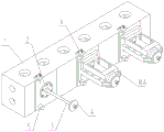
FIG. 1 is a schematic perspective view of the present utility model, wherein the right two stations are provided with motor bases, and the installation state is shown;
FIG. 2 is a front view of the present utility model without a motor mount;
FIG. 3 is a cross-sectional view A-A of FIG. 2;
fig. 4 is a B-B cross-sectional view in fig. 2.
In the figure: the fixture comprises a fixture main body, a fixture body, a disc body mounting hole, a stud mounting hole, a T-shaped connecting block, a locating disc, a stud 3, a pressing sheet 4, a locating column 5, a pressing block 6, a pressing screw 7, a pin 801, a screw I802, a screw II 803 and a motor base 10A.
Description of the embodiments
In order to make the technical problems and technical schemes solved by the utility model more clear, the utility model is further described in detail below with reference to the accompanying drawings and embodiments. It should be understood that the specific embodiments described herein are for purposes of illustration only and are not intended to limit the scope of the utility model.
In the description of the present utility model, it should be understood that the terms "longitudinal," "transverse," "upper," "lower," "front," "rear," "left," "right," "vertical," "horizontal," "top," "bottom," "inner," "outer," and the like indicate or are based on the orientation or positional relationship shown in the drawings, merely to facilitate description of the present utility model, and do not indicate or imply that the devices or elements referred to must have a particular orientation, be constructed and operated in a particular orientation, and thus should not be construed as limiting the present utility model.
In the description of the present utility model, it should also be noted that, unless explicitly specified and limited otherwise, the terms "disposed," "mounted," and "connected" are to be construed broadly, and may be, for example, fixedly connected, detachably connected, or integrally connected; can be mechanically or electrically connected; can be directly connected or indirectly connected through an intermediate medium, and can be communication between two elements. The specific meaning of the above terms in the present utility model will be understood in specific cases by those of ordinary skill in the art.
As shown in fig. 1 and 2, the efficient milling base surface clamp for the motor seat of the vertical machining center comprises a clamp main body 1, wherein the clamp main body 1 is of a square cavity structure, and is made of HT300 casting materials and good in shock resistance. The rib plate of the inner cavity is designed into a frame rib, the wall thickness is 20, the rib thickness is 16, the thickness of a used part is 50, and the stability is good. The periphery is provided with phi 50 casting holes which are lifting holes, and the T-shaped connecting block 103 at the bottom is connected with a workbench by adopting an M16 national standard, is universal with a vertical machining workbench and other equipment, and the casting is subjected to secondary aging and vibration aging to eliminate machining stress. The contact precision of the table top of the clamp main body is high and reaches 16 points per square millimeter.
As shown in fig. 1 and 2, a plurality of positioning plates 2 are installed on one side of the clamp body 1, the positioning plates 2 are arranged in a row along the center line of the side of the clamp body 1, and the positioning plates 2 are disc-shaped parts with through holes in the center, because the motor base 10A has a larger overall structure, 3-4 positioning plates 2 can be realized at most in general implementation, 3 positioning plates 2 are designed in the embodiment, namely, 3 stations are designed, and 1060 vertical centering is suitable for enterprises.
As shown in fig. 3, the positioning plate 2 is mounted in the plate body mounting hole 101 of the jig main body 1, and is fastened to the jig main body 1 by a pin 801 and a screw i 802.
As shown in fig. 3, a stud 3 is disposed along the central axis of the positioning disc 2, a pressing piece 4 is disposed at one end of the stud 3 away from the positioning disc 2, and the stud 3 is installed in a stud installation hole 102 on the clamp body 1 through a through hole of the positioning disc 2, and is installed by adopting screw threads or is inserted by adopting interference fit.
As shown in fig. 1, 2 and 4, a positioning column 5 is provided on the clamp body 1 corresponding to each positioning disk 2 at the lower side thereof, a tightening block 6 is provided above the positioning column 5 correspondingly for matching, and a tightening screw 7 is mounted on the tightening block 6.
The tightening block 6 is mounted on the jig main body 1 by a screw ii 803.
In this embodiment, the technical scheme that the positioning column 5 is disposed at the left lower side of each positioning disk 2 is adopted, and of course, the technical scheme that the positioning column 5 is disposed at the right lower side or both sides of each positioning disk 2 can also be adopted, which are all equivalent technologies.
The two positioning modes are adopted, the large end face of the workpiece is used as a main positioning face, the process hole is used as a positioning face, the external positioning column is used as another positioning face, and the clamping bolt and the jacking bolt are matched, so that the quick and simple clamping in the horizontal direction and the axial direction is realized, and the suspended top of the motor base also has clamping force.
In use, the motor cabinet processing device is suitable for motor cabinet processing of different models and sizes by replacing the positioning disc 2 and the positioning column 5 with different sizes, has better universality, and can cover 40 models of motor cabinets of enterprises in use.
The heat treatment of each positioning element adopts integral quenching HRC50, the surface hardness is very high, and the wear resistance is good. The other elements are blued. After the positioning element is arranged on the main body, the flatness and the parallelism are within 0.01, and the positioning accuracy is high.
4 processes of rough milling of a base surface, finish milling of the base surface, rough milling of a top surface, finish milling of the top surface and the like can be completed on the clamp, and the precision stability of the part is improved.
While the utility model has been described in detail in connection with specific and preferred embodiments, it will be understood by those skilled in the art that the utility model is not limited to the foregoing embodiments, but is intended to cover modifications, equivalents, and alternatives falling within the spirit and principles of the utility model.
Claims (5)
1. The utility model provides a high-efficient base surface anchor clamps that mill of vertical machining center motor seat, a serial communication port, including anchor clamps main part (1), anchor clamps main part (1) side is installed a plurality of positioning disk (2), is provided with double-screw bolt (3) along positioning disk (2) central axis, and double-screw bolt (3) are kept away from positioning disk (2) one end and are provided with preforming (4), correspond each positioning disk (2) and be provided with reference column (5) on anchor clamps main part (1) of its downside, correspond for cooperation reference column (5) top and be provided with tight piece (6) in top, install tight screw (7) in top on tight piece (6).
2. The efficient milling clamp for the motor seat of the vertical machining center according to claim 1, wherein the positioning disks (2) are arranged in a row along the side center line of the clamp body (1).
3. The efficient milling-based surface clamp for the motor seat of the vertical machining center according to claim 1 or 2, wherein the positioning disc (2) is a disc-shaped part with a through hole in the center.
4. A vertical machining center motor seat efficient milling clamp according to claim 3, characterized in that the studs (3) are mounted on the clamp body (1) through holes of the positioning disc (2).
5. A vertical machining center motor seat high efficiency milling jig according to claim 3, characterized in that the positioning posts (5) are provided on the lower left side of each positioning plate (2).
Priority Applications (1)
| Application Number | Priority Date | Filing Date | Title |
|---|---|---|---|
| CN202320091458.7U CN219170212U (en) | 2023-01-31 | 2023-01-31 | High-efficient base surface anchor clamps that mill of vertical machining center motor seat |
Applications Claiming Priority (1)
| Application Number | Priority Date | Filing Date | Title |
|---|---|---|---|
| CN202320091458.7U CN219170212U (en) | 2023-01-31 | 2023-01-31 | High-efficient base surface anchor clamps that mill of vertical machining center motor seat |
Publications (1)
| Publication Number | Publication Date |
|---|---|
| CN219170212U true CN219170212U (en) | 2023-06-13 |
Family
ID=86667969
Family Applications (1)
| Application Number | Title | Priority Date | Filing Date |
|---|---|---|---|
| CN202320091458.7U Active CN219170212U (en) | 2023-01-31 | 2023-01-31 | High-efficient base surface anchor clamps that mill of vertical machining center motor seat |
Country Status (1)
| Country | Link |
|---|---|
| CN (1) | CN219170212U (en) |
-
2023
- 2023-01-31 CN CN202320091458.7U patent/CN219170212U/en active Active
Similar Documents
| Publication | Publication Date | Title |
|---|---|---|
| CN219170212U (en) | High-efficient base surface anchor clamps that mill of vertical machining center motor seat | |
| CN108544262B (en) | Multipurpose combined clamp | |
| CN217475407U (en) | Automobile wheel hub bearing inner race boring grab | |
| CN215546928U (en) | Detachable supporting frame for front hub production | |
| CN216541046U (en) | Clamp for milling grooves of double gear workpieces | |
| CN212977462U (en) | Circular bar clamp of numerical control lathe | |
| CN211759974U (en) | Disc fixing clamp and machining system | |
| CN211361445U (en) | Drilling and milling universal fixture for shell parts of automobile air conditioner compressor | |
| CN220921629U (en) | Eccentric long shaft part machining jig | |
| CN209887114U (en) | Clamping tool for processing camera bracket | |
| CN201979153U (en) | Hydraulic milling clamp for multistation precision machining of square casing | |
| CN219254837U (en) | Milling flat tongs | |
| CN219170211U (en) | Special high-efficient milling opening clamp for vertical machining center nut seat | |
| CN216781035U (en) | Tool is fixed to gear shaft | |
| CN218362272U (en) | Magnetic pole coil edge milling clamping device | |
| CN110605660A (en) | Clamping device and clamping method for grinding thin-walled workpiece | |
| CN215615149U (en) | Slender eccentric shaft machining clamp | |
| CN220347240U (en) | Differential mechanism casing clamping device | |
| CN219484927U (en) | Vertical machining center nut seat mills installation face anchor clamps | |
| CN211939096U (en) | Lathe power chuck device | |
| CN210306842U (en) | A frock clamp for machine tool elevating platform | |
| CN219725310U (en) | Positioning and machining clamp for disc-type workpiece | |
| CN215393981U (en) | Clamp for machining hole in special-shaped part | |
| CN216097732U (en) | Turning clamp | |
| CN219465464U (en) | Milling machine slide sleeper seat convenient to clamp and milling dovetail clamp table assembly thereof |
Legal Events
| Date | Code | Title | Description |
|---|---|---|---|
| GR01 | Patent grant | ||
| GR01 | Patent grant |