CN219164432U - Air-cooled frequency converter in integrated frequency converter - Google Patents
Air-cooled frequency converter in integrated frequency converter Download PDFInfo
- Publication number
- CN219164432U CN219164432U CN202223516816.9U CN202223516816U CN219164432U CN 219164432 U CN219164432 U CN 219164432U CN 202223516816 U CN202223516816 U CN 202223516816U CN 219164432 U CN219164432 U CN 219164432U
- Authority
- CN
- China
- Prior art keywords
- air
- frequency converter
- shell
- cover plate
- radiator
- Prior art date
- Legal status (The legal status is an assumption and is not a legal conclusion. Google has not performed a legal analysis and makes no representation as to the accuracy of the status listed.)
- Active
Links
Images


Abstract
The utility model provides an air-cooled frequency converter in an integrated frequency converter, which comprises a shell and a baffle plate arranged in the shell, wherein the baffle plate separates the interior of the shell into an upper cavity and a lower cavity, an electric module accommodated in the upper cavity is arranged on the baffle plate, and a heat dissipation air duct communicated with the exterior is arranged in the lower cavity; the shell is provided with a first air inlet and a first air outlet which are communicated with the heat dissipation air duct, and the first air inlet and the first air outlet are arranged oppositely; a cooling fan, a first radiator and a second radiator are arranged in the shell at intervals and positioned behind the first air inlet, and the second radiator is positioned in front of the first air outlet; the current situation that the existing frequency conversion device installs all devices in one through cavity, and the heat dissipation wind enters the device and brings dust and rainwater into the device to cause short circuit and other influences is improved.
Description
Technical Field
The utility model relates to the field of variable frequency motors, in particular to an air-cooled frequency converter in an integrated frequency converter.
Background
The frequency conversion integrated machine is mainly applied to an outdoor scene of an oil field, and generally comprises a motor part and a frequency converter part, wherein an electric module is integrally arranged in the frequency converter, more heat is accumulated in the operation process, and the heat needs to be emitted outwards in time so as to ensure the normal operation of the internal electric module; for example, chinese patent CN112311297a discloses a frequency conversion all-in-one machine, publication date is 2021.02.02, and specifically discloses that the frequency conversion device may include: a housing having a box shape with an upper opening and including a bottom plate and a side wall, the side wall of the housing having a window formed thereon; a heat sink provided at a window of a side wall of the case, the heat sink including a housing having a square shape arranged in a vertical direction and a plurality of heat radiating fins arranged inside the housing and spaced apart in a horizontal direction; and a heat radiation fan arranged with respect to the heat radiation device to supply air to the heat radiation device; after the air is supplied by the cooling fan, the cooling device is allowed to cool, so that the IGBT module, the rectifier bridge and the like mounted on the cooling device are cooled.
The above patent discloses that the internal device of the frequency conversion device is cooled by air cooling, but all devices are installed in a through cavity, and the normal operation of the internal device, such as short circuit, is necessarily caused by dust, rainwater and the like entering along with air supply in the ventilation and heat dissipation process.
Disclosure of Invention
Aiming at the defects in the prior art, the utility model provides an air-cooled frequency converter in an integrated frequency converter, which solves the problem that the existing frequency conversion device installs all devices in a through cavity, and the entering of cooling air brings dust and rainwater to cause short circuit and other influences on the devices.
In order to achieve the above purpose, the present utility model adopts the following technical scheme:
the air-cooled frequency converter in the integrated frequency converter comprises a shell and a baffle plate arranged in the shell, wherein the baffle plate separates the interior of the shell into an upper cavity and a lower cavity, an electric module accommodated in the upper cavity is arranged on the baffle plate, and a heat dissipation air duct communicated with the exterior is arranged in the lower cavity; the shell is provided with a first air inlet and a first air outlet which are communicated with the heat dissipation air duct, and the first air inlet and the first air outlet are arranged oppositely; and a cooling fan, a first radiator and a second radiator are arranged in the shell, wherein the cooling fan and the first radiator are arranged behind the first air inlet at intervals, and the second radiator is arranged in front of the first air outlet.
Preferably, the separator is further provided with a capacitor and a reactor, which are located between the first radiator and the second radiator and are accommodated in the heat dissipation air duct.
Preferably, at least one flow dividing plate is arranged in the heat dissipation air duct, and the flow dividing plate divides the heat dissipation air duct into a plurality of flow channels.
Preferably, the first air inlet and the first air outlet are both provided with grids.
Preferably, a second air inlet and a second air outlet which are communicated with the upper cavity are formed in the shell, and a ventilation fan is arranged at the second air inlet or the second air outlet;
the second air inlet and the second air outlet are both provided with ventilating fans for water proofing and dust proofing.
Preferably, the casing includes a first bottom shell having an opening structure and a first cover plate rotatably mounted on the first bottom shell through a hinge, a first sealing ring is disposed between the first cover plate and the first bottom shell, and the first cover plate is fixedly connected to the first bottom shell through a fastener.
Preferably, the partition plate is fixedly installed in the first bottom case.
Preferably, the first cover plate is fixedly provided with a control box, the control box comprises a second bottom shell fixedly arranged on the first cover plate and a second cover plate rotatably arranged on the second bottom shell through a hinge, a second sealing ring is arranged between the second cover plate and the second bottom shell, and the second cover plate is fixedly connected to the second bottom shell through a fastener.
Preferably, the first cover plate and the second cover plate are both provided with handle structures.
Preferably, a waterproof connector for penetrating the cable is installed on the second bottom shell.
Compared with the prior art, the utility model has the following beneficial effects:
the shell is divided into an upper cavity and a lower cavity through the partition plate, the electrified electric module is installed in the upper cavity, the first air inlet, the first air outlet, the cooling fan, the wantonly radiator, the second radiator and the like are arranged in the radiating air duct in the lower cavity, internal heat is taken away through cold air entering the lower cavity, heat in the upper cavity is taken away through the heat conduction effect of the partition plate, even dust and rainwater enter the radiating air duct and cannot influence the electric module located in the upper cavity, so that the protection requirement of the upper cavity is also guaranteed under the condition of realizing internal heat radiation, the whole frequency converter can well operate, and the whole protection level can reach IP54.
Drawings
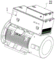
FIG. 1 is a schematic diagram of an embodiment of the present utility model;
FIG. 2 is a schematic view of a second view structure according to an embodiment of the present utility model;
FIG. 3 is a schematic cross-sectional view of an embodiment of the present utility model;
FIG. 4 is a schematic top view of an embodiment of the present utility model;
FIG. 5 is a schematic diagram of an application state structure according to an embodiment of the present utility model;
in the drawing the view of the figure,
the air conditioner comprises a shell 1, a partition plate 2, an upper cavity 3, a lower cavity 4, a heat dissipation air duct 5, a first air inlet 6, a first air outlet 7, a cooling fan 8, a first radiator 9, a second radiator 10, a capacitor 11, a reactor 12, a splitter plate 13, a circulation cavity 14, a grid 15, a second air inlet 16, a second air outlet 17, a ventilation fan 18, a ventilation fan 19, a first bottom shell 20, a first cover plate 21, a control box 22, a second bottom shell 23, a second cover plate 24, a handle structure 25 and a waterproof joint 26.
Detailed Description
The present utility model will be further described with reference to the accompanying drawings and specific examples, which are not intended to be limiting, so that those skilled in the art will better understand the utility model and practice it.
As shown in fig. 1 to 5, an embodiment of the present utility model proposes an air-cooled frequency converter in an integrated frequency converter, where the air-cooled frequency converter is installed on a motor to perform modularized integration, so that separation from heat dissipation in the motor can be achieved, and in order to adapt to reliable operation in an oilfield environment, the whole frequency converter is mainly cooled by adopting an air-cooled mode, so that operation stability is improved; the heat dissipation device comprises a shell 1 and a partition board 2 arranged in the shell 1, wherein the partition board 2 divides the interior of the shell 1 into an upper cavity 3 and a lower cavity 4, an electric module accommodated in the upper cavity 3 is arranged on the partition board 2, and a heat dissipation air duct 5 communicated with the outside is arranged in the lower cavity 4; the whole shell 1 is divided into the upper cavity 3 through the partition plate 2, and the main electric module is installed in the upper cavity 3, so that the main electric module is separated from the heat dissipation air duct 5 in the lower cavity 4, namely dust, rainwater and the like which are uniformly distributed in the heat dissipation air duct 5 flow into the upper cavity 3, and the electric module in the upper cavity 3 can be ensured to reliably operate.
Specifically, be equipped with the intercommunication on the casing 1 the first air intake 6 and the first air outlet 7 of heat dissipation wind channel 5, first air intake 6 with first air outlet 7 sets up relatively, and still install in the casing 1 and be located first air intake 6 rear and the cooling fan 8 that the interval set up, first radiator 9, and be located the second radiator 10 of first air outlet 7 the place ahead, the wind that gets into through first air intake 6 is discharged from first air outlet 7 after cooling fan 8, first radiator 9, second radiator 10 to form cooling cycle, take away the heat that the electric module that installs on baffle 2 produced together through the heat conduction effect of baffle 2 simultaneously and realize the heat dissipation, thereby guarantee that whole casing 1 is inside to have good radiating effect, last reliable operation.
In order to dissipate heat of the devices with high heat generation capacity, such as the capacitor 11 and the reactor 12, and good protection performance, the capacitor 11 and the reactor 12 are installed between the first radiator 9 and the second radiator 10 and are accommodated in the heat dissipation air duct 5, so that heat generated by the capacitor 11 and the reactor 12 is rapidly dissipated through the heat dissipation air duct 5, and dust and rainwater in the lower cavity 4 cannot influence the capacitor 11 and the reactor 12.
Further, at least one flow dividing plate 13 is disposed in the heat dissipation air duct 5, the flow dividing plate 13 divides the heat dissipation air duct 5 into a plurality of flow channels 14, and a cooling fan 8, a first radiator 9, a second radiator 10, a capacitor 11 and a reactor 12 are disposed in each flow channel 14, so that good heat dissipation can be achieved in each flow channel 14, and the heat dissipation effect of the whole inside is improved.
In order to isolate larger sundries, insect mice and the like in the air entering the heat dissipation air duct 5 to a certain extent, the first air inlet 6 and the first air outlet 7 are provided with grids 15, the grids 15 are of a net structure, and the grid size can block most of the larger sundries and the insect mice so as to protect the inside.
Although some heat in the upper cavity 3 can be led out through the action of the partition plate 2, in the operation process, the condition of untimely heat conduction still possibly exists, therefore, the second air inlet 16 and the second air outlet 17 which are communicated with the upper cavity 3 are formed in the shell 1, the second air inlet 16 or the second air outlet 17 are provided with the ventilation fan 18, the second air inlet 16 and the second air outlet 17 are provided with the ventilation fan 19 for preventing water and dust, and the heat dissipation effect in the upper cavity 3 is improved by adding the ventilation fan 18, the second air inlet 16 and the second air outlet 17 for assisting heat dissipation under the condition of keeping the upper cavity 3 waterproof and dustproof.
Specifically, the housing 1 includes a first bottom case 20 having an opening structure, and a first cover plate 21 rotatably mounted on the first bottom case 20 through a hinge, a first sealing ring is disposed between the first cover plate 21 and the first bottom case 20, and the first cover plate 21 is fixedly connected to the first bottom case 20 through a fastener; the first cover 21 can be opened with respect to the first bottom case 20, thereby facilitating maintenance of the internal electrical module.
Wherein, the partition board 2 is fixedly installed in the first bottom shell 20, and specifically, the partition board can be fixed by adopting a welding mode.
The wiring of the electric module in the frequency converter is connected through a control box 22, the control box 22 is fixedly installed on the first cover plate 21, the control box 22 comprises a second bottom shell 23 fixedly installed on the first cover plate 21 and a second cover plate 24 rotatably installed on the second bottom shell 23 through a hinge, a second sealing ring is arranged between the second cover plate 24 and the second bottom shell 23, and the second cover plate 24 is fixedly connected on the second bottom shell 23 through a fastener; the second cover 24 can be opened with respect to the second bottom case 23, and then the wiring and the like in the control box 22 can be maintained and handled. Meanwhile, a waterproof connector 26 for threading a cable is mounted on the second bottom case 23.
Meanwhile, the handle structures 25 are arranged on the first cover plate 21 and the second cover plate 24, so that the first cover plate 21 and the second cover plate 24 can be conveniently held and carried through the handle structures 25 when being opened.
In the description of the present utility model, it should be understood that the terms "orientation" or "positional relationship" are based on the orientation or positional relationship shown in the drawings, and are merely for convenience of description and to simplify the description, rather than to indicate or imply that the apparatus or elements referred to must have a particular orientation, be constructed and operate in a particular orientation, and therefore should not be construed as limiting the utility model.
In the present utility model, unless explicitly specified and limited otherwise, the terms "mounted," "connected," "secured," and the like are to be construed broadly, and may be, for example, fixedly connected, detachably connected, or integrally formed; can be mechanically or electrically connected; can be directly connected or indirectly connected through an intermediate medium, and can be communicated with the inside of two elements or the interaction relationship of the two elements. The specific meaning of the above terms in the present utility model can be understood by those of ordinary skill in the art according to the specific circumstances.
In the description of the present utility model, it should be noted that, directions or positional relationships indicated by terms such as "center", "upper", "lower", "left", "right", "inner", "outer", etc., are directions or positional relationships based on those shown in the drawings, or are directions or positional relationships conventionally put in use of the inventive product, are merely for convenience of describing the present utility model and simplifying the description, and are not indicative or implying that the apparatus or element to be referred to must have a specific direction, be constructed and operated in a specific direction, and thus should not be construed as limiting the present utility model. Furthermore, the terms "first," "second," and the like, are used merely to distinguish between descriptions and should not be construed as indicating or implying relative importance.
Finally, it is noted that the above embodiments are only for illustrating the technical solution of the present utility model and not for limiting the same, and although the present utility model has been described in detail with reference to the preferred embodiments, it should be understood by those skilled in the art that modifications and equivalents may be made thereto without departing from the spirit and scope of the technical solution of the present utility model, which is intended to be covered by the scope of the claims of the present utility model.
Claims (10)
1. Air-cooled frequency converter among the integrative frequency converter, its characterized in that: the device comprises a shell (1) and a partition board (2) arranged in the shell (1), wherein the partition board (2) separates an upper cavity (3) and a lower cavity (4) inside the shell (1), an electric module accommodated in the upper cavity (3) is arranged on the partition board (2), and a heat dissipation air duct (5) communicated with the outside is arranged in the lower cavity (4);
a first air inlet (6) and a first air outlet (7) which are communicated with the heat dissipation air duct (5) are formed in the shell (1), and the first air inlet (6) and the first air outlet (7) are arranged oppositely;
and a cooling fan (8), a first radiator (9) and a second radiator (10) are arranged in the shell (1) at the rear of the first air inlet (6) at intervals, and the second radiator is positioned in front of the first air outlet (7).
2. The air-cooled frequency converter in an integrated frequency converter according to claim 1, wherein: the partition board (2) is also provided with a capacitor (11) and a reactor (12) which are positioned between the first radiator (9) and the second radiator (10) and are accommodated in the radiating air duct (5).
3. An air-cooled frequency converter in an integrated frequency converter according to claim 2, characterized in that: at least one flow dividing plate (13) is arranged in the heat dissipation air duct (5), and the flow dividing plate (13) divides the heat dissipation air duct (5) into a plurality of flow channels (14).
4. An air-cooled frequency converter in an integrated frequency converter according to any of claims 1-3, characterized in that: the first air inlet (6) and the first air outlet (7) are both provided with grids (15).
5. The air-cooled frequency converter in an integrated frequency converter according to claim 4, wherein: a second air inlet (16) and a second air outlet (17) which are communicated with the upper cavity (3) are formed in the shell (1), and a ventilation fan (18) is arranged at the second air inlet (16) or the second air outlet (17);
the second air inlet (16) and the second air outlet (17) are both provided with a waterproof and dustproof ventilating fan (19).
6. The air-cooled frequency converter in an integrated frequency converter according to claim 5, wherein: the shell (1) comprises a first bottom shell (20) with an opening structure and a first cover plate (21) rotatably installed on the first bottom shell (20) through a hinge, a first sealing ring is arranged between the first cover plate (21) and the first bottom shell (20), and the first cover plate (21) is fixedly connected to the first bottom shell (20) through a fastener.
7. The air-cooled frequency converter in an integrated frequency converter according to claim 6, wherein: the partition board (2) is fixedly arranged in the first bottom shell (20).
8. The air-cooled frequency converter in an integrated frequency converter according to claim 6, wherein: the control box (22) is fixedly mounted on the first cover plate (21), the control box (22) comprises a second bottom shell (23) fixedly mounted on the first cover plate (21) and a second cover plate (24) rotatably mounted on the second bottom shell (23) through a hinge, a second sealing ring is arranged between the second cover plate (24) and the second bottom shell (23), and the second cover plate (24) is fixedly connected to the second bottom shell (23) through a fastener.
9. The air-cooled frequency converter in an integrated frequency converter according to claim 8, wherein: and the first cover plate (21) and the second cover plate (24) are provided with handle structures (25).
10. The air-cooled frequency converter in an integrated frequency converter according to claim 8, wherein: and a waterproof connector (26) for penetrating the cable is arranged on the second bottom shell (23).
Priority Applications (1)
| Application Number | Priority Date | Filing Date | Title |
|---|---|---|---|
| CN202223516816.9U CN219164432U (en) | 2022-12-28 | 2022-12-28 | Air-cooled frequency converter in integrated frequency converter |
Applications Claiming Priority (1)
| Application Number | Priority Date | Filing Date | Title |
|---|---|---|---|
| CN202223516816.9U CN219164432U (en) | 2022-12-28 | 2022-12-28 | Air-cooled frequency converter in integrated frequency converter |
Publications (1)
| Publication Number | Publication Date |
|---|---|
| CN219164432U true CN219164432U (en) | 2023-06-09 |
Family
ID=86619146
Family Applications (1)
| Application Number | Title | Priority Date | Filing Date |
|---|---|---|---|
| CN202223516816.9U Active CN219164432U (en) | 2022-12-28 | 2022-12-28 | Air-cooled frequency converter in integrated frequency converter |
Country Status (1)
| Country | Link |
|---|---|
| CN (1) | CN219164432U (en) |
Cited By (1)
| Publication number | Priority date | Publication date | Assignee | Title |
|---|---|---|---|---|
| CN116867214A (en) * | 2023-09-04 | 2023-10-10 | 扬州力天智能科技有限公司 | Network cabinet convenient for heat dissipation |
-
2022
- 2022-12-28 CN CN202223516816.9U patent/CN219164432U/en active Active
Cited By (2)
| Publication number | Priority date | Publication date | Assignee | Title |
|---|---|---|---|---|
| CN116867214A (en) * | 2023-09-04 | 2023-10-10 | 扬州力天智能科技有限公司 | Network cabinet convenient for heat dissipation |
| CN116867214B (en) * | 2023-09-04 | 2023-11-14 | 扬州力天智能科技有限公司 | Network cabinet convenient for heat dissipation |
Similar Documents
| Publication | Publication Date | Title |
|---|---|---|
| CN219164432U (en) | Air-cooled frequency converter in integrated frequency converter | |
| CN111578387A (en) | Electric control box and window type air conditioner | |
| CN205901571U (en) | Converter casing | |
| CN209962840U (en) | Novel cooling structure of dry-type transformer | |
| CN111207451A (en) | Electric control box and window type air conditioner | |
| JP7064998B2 (en) | Stationary power converter | |
| JP4042520B2 (en) | Communication equipment mounting structure and heat dissipation method | |
| CN216346707U (en) | Air conditioner outdoor unit and air conditioner | |
| CN216844927U (en) | Automatically controlled box, control assembly and air condensing units | |
| CN215187943U (en) | Automatically controlled box and refrigerator set for refrigerator car | |
| CN212278698U (en) | Outdoor air cooling machine box | |
| CN211765022U (en) | Charging pile | |
| CN210624740U (en) | Electrical box assembly, outdoor unit and air conditioner | |
| JP2003139352A (en) | Electric device unit for outdoor machine and outdoor machine for air conditioner | |
| CN211119714U (en) | Outdoor unit of heat pump air conditioner | |
| CN211575306U (en) | Electric control box and window type air conditioner | |
| CN114183904A (en) | Electrical box, air conditioner and control method | |
| CN211429848U (en) | Electrical cabinet with sealing performance and heat dissipation effect | |
| CN111207452A (en) | Electric control box and window type air conditioner | |
| CN111219798A (en) | Window type air conditioner | |
| CN219346648U (en) | Air conditioner | |
| CN215500135U (en) | Sealed air-cooled cabinet | |
| CN218827396U (en) | Guarantee power supply unit of outdoor use | |
| CN217823835U (en) | Intelligent comprehensive distribution box | |
| CN211575305U (en) | Electric control box and window type air conditioner |
Legal Events
| Date | Code | Title | Description |
|---|---|---|---|
| GR01 | Patent grant | ||
| GR01 | Patent grant |