CN219151396U - Bending mechanism convenient for feeding - Google Patents
Bending mechanism convenient for feeding Download PDFInfo
- Publication number
- CN219151396U CN219151396U CN202320254101.6U CN202320254101U CN219151396U CN 219151396 U CN219151396 U CN 219151396U CN 202320254101 U CN202320254101 U CN 202320254101U CN 219151396 U CN219151396 U CN 219151396U
- Authority
- CN
- China
- Prior art keywords
- feeding
- bracket
- water
- feeding box
- motor
- Prior art date
- Legal status (The legal status is an assumption and is not a legal conclusion. Google has not performed a legal analysis and makes no representation as to the accuracy of the status listed.)
- Active
Links
Images


Landscapes
- Bending Of Plates, Rods, And Pipes (AREA)
Abstract
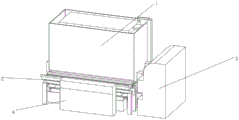
The utility model relates to the technical field of bending equipment and discloses a bending mechanism convenient to feed, which comprises a discharging mechanism and a feeding mechanism, wherein the discharging mechanism comprises a feeding box, a discharging hole is formed in the position, close to the lower end, of the front end of the feeding box, a first bracket is fixedly arranged at the discharging hole, a discharging roller is rotatably arranged in the first bracket, the feeding mechanism comprises a second bracket, rotating rollers are rotatably arranged in the positions, close to the upper positions, of two sides of the corresponding surface in the second bracket, two rotating rollers are movably sleeved with hollowed-out belts, a correction plate is fixedly arranged at the position, close to the center, of the upper end face of the second bracket, a first water collecting tank is fixedly arranged at the lower end of the second bracket, a bending machine main body is movably arranged at one side of the feeding mechanism, and the feeding mechanism is movably arranged at one side of the discharging mechanism. According to the utility model, the aluminum strips are conveyed to the hollowed-out belt through the discharging roller, the aluminum strips are not placed one by one manually, and the correction plates can be aligned to the positions of the aluminum strips.
Description
Technical Field
The utility model relates to the technical field of bending equipment, in particular to a bending mechanism convenient for feeding.
Background
The hollow aluminum strip is one of materials for producing the hollow glass, the quality of the hollow aluminum strip is directly related to the service life of the hollow glass and the heat insulation function, and the hollow aluminum strip has the main effects of uniformly separating two sides or a plurality of pieces of glass from each other in the hollow glass and effectively supporting the two sides or the plurality of pieces of glass, so that the heat insulation effect of the hollow glass is effectively improved, and a full-automatic bending machine is often used in the processing process of the glass aluminum strip at present for bending the hollow glass aluminum strip.
The prior patent (publication number: CN 215824120U) discloses a novel full-automatic glass aluminum strip bending machine, which comprises an automatic bending machine body and a feeding mechanism, wherein the feeding mechanism is arranged on the left side of the automatic bending machine body and comprises a fixing plate, a transmission mechanism and an adjusting limiting assembly, and the transmission mechanism and the adjusting limiting assembly are fixedly arranged on the front surface of the fixing plate. This novel full-automatic bender of glass aluminium strip can drive the direction subassembly through the drive assembly who sets up and rotate, can make spacing rolling down movement and laminating mutually with the upper surface of glass aluminium strip through rotating the screw rod, and then can carry out spacing transmission to the glass aluminium strip of co-altitude not, need artifical feeding, intensity of labour is little, the process is simple, labour saving and time saving, the workman of being convenient for uses, production efficiency has been improved, and clean the subassembly through setting up can clear up the dust of its upper surface at the spacing transmission in-process of glass aluminium strip, guaranteed the cleanliness of glass aluminium strip effectively, the processing effect of glass aluminium strip has been improved.
The inventors found that the following problems exist in the prior art in the process of implementing the present utility model: 1. when the equipment is filled, raw materials are required to be put into the discharge hole once by manpower, the labor intensity is high, personnel are required to stare at all times, the raw materials cannot be stocked up for automatic feeding, the process is complex, and the production efficiency is not improved; 2. when the raw materials are cleaned, the sponge can only clean the upper surface and the lower surface of the aluminum strip, and the surface of the aluminum strip cannot be cleaned completely.
Therefore, it is needed to provide a bending mechanism which is convenient for feeding.
Disclosure of Invention
The utility model aims to solve the defects in the prior art, and provides a bending mechanism convenient for feeding, which can be used for putting required glass aluminum strips into a feeding box at one time, filling the glass aluminum strips through a discharging roller, controlling the discharging speed by adjusting a motor, conveying the glass aluminum strips to a bending machine by the feeding mechanism, and cleaning foreign matters on the surface of the aluminum strips by a water spraying plate.
In order to achieve the above purpose, the present utility model provides the following technical solutions:
the feeding device comprises a discharging mechanism and a feeding mechanism, wherein the discharging mechanism comprises a feeding box, a feeding door is connected to one side of the feeding box through a hinge, a discharging hole is formed in the front end of the feeding box and in the lower position, a first bracket is fixedly arranged at the discharging hole, and a discharging roller is rotatably arranged in the first bracket;
the feeding mechanism comprises a second bracket, rotating rollers are rotatably arranged on two sides of the corresponding surface of the second bracket close to the upper positions, hollowed-out belts are movably sleeved on the two rotating rollers, correction plates are fixedly arranged on the upper end surfaces of the second bracket close to the center, a first water collecting tank is fixedly arranged at the lower end of the second bracket, a bending machine main body is movably arranged on one side of the feeding mechanism, and the feeding mechanism is movably arranged on one side of the discharging mechanism;
through above-mentioned technical scheme, can put into the feeding incasement with the aluminium strip, take the fretwork belt with the aluminium strip through the discharging roller on, the correction board can be with aluminium strip position alignment, in passing through the fretwork belt conveys the bender with the aluminium strip.
Further, a plurality of drain holes are formed in the inner lower end face of the feeding box, and the lower end face of the feeding box is fixedly connected with a second water collecting box;
through above-mentioned technical scheme, the setting of wash port can leak No. two header tanks with watering plate exhaust water through the wash port in, collect recycle with abluent water through No. two header tanks.
Further, a first water delivery pipe is fixedly connected to one side of the lower end face of the second water collection tank, and the first water delivery pipe is connected with a water pump in a threaded manner;
through the technical scheme, the water of the second water collecting tank can be sent into the water pump through the first water conveying pipe, water is supplied to the water spraying plate, and water resources can be saved.
Further, a water sprinkling plate is fixedly arranged on the upper end face of the feeding box, and a second water pipe is connected to one side, close to the water pump, of the upper end face of the water sprinkling plate in a threaded manner;
through above-mentioned technical scheme, take water to the watering board through the water pumper through No. two raceway, wash the aluminium strip through watering board conveying water to the feeding incasement.
Further, one end of the second water pipe is connected to the water pump in a threaded mode, a blow dryer is movably arranged on one side of the second support, and the output end of the blow dryer is aligned to the upper end face of the hollowed-out belt;
through above-mentioned technical scheme, there are some water stain still on the aluminium strip surface that comes out through the discharging roller, can weather the aluminium strip surface through the weather machine and carry out the processing of drying.
Further, a third bracket is fixedly connected to two sides of the feeding box, a first motor is fixedly arranged on one side of the third bracket, and the first motor is connected to one side of the discharging roller through a belt;
through above-mentioned technical scheme, motor No. one is the power take off of discharging roller, can drive the discharging roller through the belt and operate.
Further, a second motor is fixedly arranged on one side, close to the first motor, of the second bracket, and the second motor is connected to the rotating roller through a belt;
through the technical scheme, the second motor is the power output of the rotating roller, and the rotating roller can be driven by the belt to operate.
The utility model has the following beneficial effects:
1. according to the bending mechanism convenient to feed, required glass aluminum strips can be placed into the feeding box, the feeding hole is not required to be filled manually, the rotating speed of the motor can be adjusted according to the required speed, and then the discharging roller is driven, so that the feeding speed can be adjusted very conveniently, and the working efficiency is greatly improved.
2. According to the bending mechanism convenient for feeding, provided by the utility model, the water spraying plate is arranged on the feeding box, so that foreign matters on the surface of the aluminum strips can be washed away, water can be recovered by the water pump and then can be recycled to the water spraying plate, water resources can be effectively saved, and water can be replaced through the first water conveying pipe.
Drawings
FIG. 1 is an isometric view of a bending mechanism for facilitating feeding according to the present utility model;
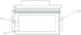
FIG. 2 is a side view of the discharging mechanism, the blow dryer and the feeding mechanism according to the present utility model;
FIG. 3 is a bottom isometric view of a bending mechanism for facilitating feeding in accordance with the present utility model;
FIG. 4 is an isometric view of a discharge mechanism and a feed mechanism according to the present utility model;
fig. 5 is a top view of a bending mechanism for feeding convenience according to the present utility model.
Legend description:
1. a discharging mechanism; 101. a feed box; 102. a feed gate; 103. a discharge port; 104. a first bracket; 105. a discharge roller; 106. a drain hole; 107. a second water collecting tank; 108. a first water pipe; 109. a water pump; 110. a sprinkler plate; 111. a second water pipe; 112. a third bracket; 113. a motor I; 114. a motor II; 2. a feeding mechanism; 201. a second bracket; 202. a rotating roller; 203. hollowed-out belts; 204. a correction plate; 205. a first water collecting tank; 3. a bending machine body; 4. and (5) drying the machine.
Detailed Description
The following description of the embodiments of the present utility model will be made clearly and completely with reference to the accompanying drawings, in which it is apparent that the embodiments described are only some embodiments of the present utility model, but not all embodiments. All other embodiments, which can be made by those skilled in the art based on the embodiments of the utility model without making any inventive effort, are intended to be within the scope of the utility model.
Example 1
Referring to fig. 1-5, one embodiment provided by the present utility model is: the aluminum strip feeding device comprises a discharging mechanism 1 and a feeding mechanism 2, wherein the discharging mechanism 1 comprises a feeding box 101, a feeding door 102 is connected to one side of the feeding box 101 at an upper position through a hinge, the feeding door 102 is provided with a discharging hole 103 which is convenient for conveying an aluminum strip, the front end of the feeding box 101 is provided with a discharging roller 105 at a lower position, the aluminum strip passes through the discharging hole 103 to reach the discharging roller 105, a first bracket 104 is fixedly arranged at the discharging hole 103, and the first bracket 104 is rotationally provided with the discharging roller 105;
the feeding mechanism 2 comprises a second bracket 201, rotating rollers 202 are respectively arranged on two sides of the corresponding surface of the second bracket 201 in a rotating manner near the upper positions, hollow belts 203 are movably sleeved on the two rotating rollers 202, a correction plate 204 is fixedly arranged on the upper end surface of the second bracket 201 near the center, a first water collecting tank 205 is fixedly arranged at the lower end of the second bracket 201, a bending machine main body 3 is movably arranged on one side of the feeding mechanism 2, a plurality of water draining holes 106 are formed in the lower end surface of the feeding mechanism 101, cleaned water can flow into the second water collecting tank 107 through the water draining holes 106, the lower end surface of the feeding box 101 is fixedly connected with the second water collecting tank 107, a first water conveying pipe 108 is fixedly connected to one side of the lower end surface of the second water collecting tank 107, a water conveying pipe 109 is in threaded connection with a water pump 109, a second water conveying pipe 111 is fixedly arranged on the upper end surface of the first water conveying tank 101, one side of the upper end surface of the water conveying plate 110 near the water pump 109 is in threaded connection with a second water conveying pipe 111, one end of the second water conveying motor 111 is in threaded connection with a second water conveying motor 109, a second motor 201 is fixedly connected with one side of the second motor 113, a second motor 201 is fixedly arranged on one side of the upper end surface of the second motor 201 near the second motor 113, and is fixedly connected with the second motor 113 is fixedly arranged on one side of the upper end of the second motor 113, and is fixedly connected with the second motor 113 is connected with the second motor 113, and is fixedly connected with one side of the first motor 113, and is near the upper end of the first motor 201 is connected with a motor 113.
Working principle: the feeding door 102 on the feeding box 101 is opened, aluminum strips are placed into the feeding box to start to clean the aluminum strips through the water spraying plate 110, the cleaned water flows into the second water collecting tank 107 through the water draining holes 106, then the water is regulated onto the water spraying plate 110 through the water pump 109, water circulation can be saved, the first water conveying pipe 108 can be unscrewed to be replaced when the water is too dirty, the cleaned aluminum strips are brought onto the hollowed-out belt 203 through the discharging roller 105, residual water stains on the aluminum strips are collected in the first water collecting tank 205 through the hollowed-out belt 203, and the residual water stains on the aluminum strips can be dried by the blow dryer 4 and then transferred onto the bending machine main body 3.
Finally, it should be noted that: the foregoing description of the preferred embodiments of the present utility model is not intended to be limiting, but rather, although the present utility model has been described in detail with reference to the foregoing embodiments, it will be apparent to those skilled in the art that modifications may be made to the embodiments described, or equivalents may be substituted for elements thereof, and any modifications, equivalents, improvements or changes may be made without departing from the spirit and principles of the present utility model.
Claims (7)
1. The utility model provides a mechanism of bending convenient to feeding, includes discharge mechanism (1) and feeding mechanism (2), its characterized in that: the feeding mechanism (1) comprises a feeding box (101), a feeding door (102) is connected to one side of the feeding box (101) at an upper position through a hinge, a discharging hole (103) is formed in the front end of the feeding box (101) at a lower position, a first bracket (104) is fixedly arranged at the discharging hole (103), and a discharging roller (105) is rotationally arranged in the first bracket (104);
feeding mechanism (2) are including No. two support (201), no. two support (201) are interior one side both sides all rotate and are provided with rotor (202) near the upper position, two rotor (202) go up the movable sleeve and are equipped with fretwork belt (203), no. two support (201) up end is close to the fixed correction board (204) that are provided with in position in center, no. two support (201) lower extreme is fixed and is provided with first header tank (205), feeding mechanism (2) one side activity is provided with bender main part (3), feeding mechanism (2) activity sets up one side in discharge mechanism (1).
2. The bending mechanism facilitating feeding according to claim 1, wherein: a plurality of drain holes (106) are formed in the inner lower end face of the feeding box (101), and a second water collecting tank (107) is fixedly connected to the lower end face of the feeding box (101).
3. The bending mechanism facilitating feeding according to claim 2, wherein: a first water delivery pipe (108) is fixedly connected to one side of the lower end face of the second water collection tank (107), and the first water delivery pipe (108) is in threaded connection with a water pump (109).
4. The bending mechanism facilitating feeding according to claim 1, wherein: the feeding box is characterized in that a sprinkling plate (110) is fixedly arranged on the upper end face of the feeding box (101), and a second water pipe (111) is connected to one side, close to the water pump (109), of the upper end face of the sprinkling plate (110) in a threaded mode.
5. The bending mechanism facilitating feeding as defined in claim 4, wherein: one end of the second water delivery pipe (111) is in threaded connection with the water pump (109), a dryer (4) is movably arranged on one side of the second support (201), and the output end of the dryer (4) is aligned with the upper end face of the hollowed-out belt (203).
6. The bending mechanism facilitating feeding according to claim 1, wherein: the feeding box is characterized in that a third bracket (112) is fixedly connected to two sides of the feeding box (101), a first motor (113) is fixedly arranged on one side of the third bracket (112), and the first motor (113) is connected to one side of the discharging roller (105) through a belt.
7. The bending mechanism facilitating feeding according to claim 1, wherein: and a second motor (114) is fixedly arranged on one side, close to the first motor (113), of the second bracket (201), and the second motor (114) is connected to the rotating roller (202) through a belt.
Priority Applications (1)
| Application Number | Priority Date | Filing Date | Title |
|---|---|---|---|
| CN202320254101.6U CN219151396U (en) | 2023-02-20 | 2023-02-20 | Bending mechanism convenient for feeding |
Applications Claiming Priority (1)
| Application Number | Priority Date | Filing Date | Title |
|---|---|---|---|
| CN202320254101.6U CN219151396U (en) | 2023-02-20 | 2023-02-20 | Bending mechanism convenient for feeding |
Publications (1)
| Publication Number | Publication Date |
|---|---|
| CN219151396U true CN219151396U (en) | 2023-06-09 |
Family
ID=86641945
Family Applications (1)
| Application Number | Title | Priority Date | Filing Date |
|---|---|---|---|
| CN202320254101.6U Active CN219151396U (en) | 2023-02-20 | 2023-02-20 | Bending mechanism convenient for feeding |
Country Status (1)
| Country | Link |
|---|---|
| CN (1) | CN219151396U (en) |
Cited By (1)
| Publication number | Priority date | Publication date | Assignee | Title |
|---|---|---|---|---|
| CN116586532A (en) * | 2023-07-19 | 2023-08-15 | 河北中迈玻璃科技有限公司 | Aluminum strip bending machine for producing toughened hollow glass and working method thereof |
-
2023
- 2023-02-20 CN CN202320254101.6U patent/CN219151396U/en active Active
Cited By (2)
| Publication number | Priority date | Publication date | Assignee | Title |
|---|---|---|---|---|
| CN116586532A (en) * | 2023-07-19 | 2023-08-15 | 河北中迈玻璃科技有限公司 | Aluminum strip bending machine for producing toughened hollow glass and working method thereof |
| CN116586532B (en) * | 2023-07-19 | 2023-09-12 | 河北中迈玻璃科技有限公司 | Aluminum strip bending machine for producing toughened hollow glass and working method thereof |
Similar Documents
| Publication | Publication Date | Title |
|---|---|---|
| CN219151396U (en) | Bending mechanism convenient for feeding | |
| CN209128704U (en) | A kind of textile processing cleaning device | |
| CN110425863B (en) | High-efficiency energy-saving glass cleaning dryer | |
| CN108672343A (en) | A kind of adjustable double-sided glass cleaning machine in dry air port | |
| CN213223454U (en) | Water-saving washing equipment for aluminum processing | |
| CN114733917B (en) | Strip steel surface residual oil cleaning equipment for strip steel production | |
| CN215320632U (en) | Tectorial membrane device of FRP daylighting board production usefulness | |
| CN213444848U (en) | Passive rolling brush cleaner | |
| CN212770446U (en) | Tempering furnace for producing tempered glass | |
| CN210729661U (en) | High-strength composite mineral material crushing and screening integrated device | |
| CN111891684A (en) | Suspension type washing and spraying integrated conveyor | |
| CN113397186A (en) | Raw materials belt cleaning device is used in fruit wine production | |
| CN221638855U (en) | Spray cleaning device | |
| CN219210805U (en) | Bathroom presss from both sides surface cleaning machine | |
| CN214004679U (en) | Energy-saving roll-type leather staking equipment | |
| CN219527049U (en) | Cloth drying equipment convenient to dismouting | |
| CN221017654U (en) | Cleaning and drying assembly for processing traditional Chinese medicinal materials | |
| CN111747662A (en) | Automatic frosted glass production line | |
| CN118204375A (en) | Belt cleaning device in brass plate area that cleaning effect is good | |
| CN221657324U (en) | Glass cleaning machine is used in door and window production | |
| CN216220101U (en) | Fresh corn spraying and cleaning machine | |
| CN220862288U (en) | Automatic change glass cleaning desiccator | |
| CN221339202U (en) | Cooling device for plastic part production | |
| CN221515320U (en) | Various steel tile washs drying equipment | |
| CN212597542U (en) | Equipment for washing and removing trace impurities in electronic-grade chemicals |
Legal Events
| Date | Code | Title | Description |
|---|---|---|---|
| GR01 | Patent grant | ||
| GR01 | Patent grant |