CN219136576U - Water purification station system - Google Patents
Water purification station system Download PDFInfo
- Publication number
- CN219136576U CN219136576U CN202223031490.0U CN202223031490U CN219136576U CN 219136576 U CN219136576 U CN 219136576U CN 202223031490 U CN202223031490 U CN 202223031490U CN 219136576 U CN219136576 U CN 219136576U
- Authority
- CN
- China
- Prior art keywords
- water
- tank
- communicated
- fluidized bed
- filter
- Prior art date
- Legal status (The legal status is an assumption and is not a legal conclusion. Google has not performed a legal analysis and makes no representation as to the accuracy of the status listed.)
- Active
Links
Images


Abstract
The utility model belongs to the field of water purification treatment equipment, and particularly relates to a water purification station system which comprises a raw water tank, a flocculation device, a fluidized bed sedimentation tank, a D-type filter tank, a water seal tank and a clean water tank which are sequentially connected through pipelines; the flocculation device is fixed on the outer side wall of the fluidized bed sedimentation tank, the flocculation device is communicated with the fluidized bed sedimentation tank through a pipeline, and raw water enters the fluidized bed sedimentation tank to realize separation of mud and water after being subjected to flocculation treatment by the flocculation device; the sediment outlet end of the fluidized bed sedimentation tank is also connected with a mud storage tank; the clean water outlet end of the fluidized bed sedimentation tank is connected with the water inlet of the D-shaped filter tank through a pipeline; a backwashing air inlet pipe is arranged on the D-shaped filter tank, and a backwashing fan is arranged on the backwashing air inlet pipe; the clear water outlet end of the D-type filter tank is communicated with the inlet end of the clear water tank through a pipeline; the utility model has the advantages of water and energy saving, cost saving, high water purifying efficiency and excellent water quality of the purified water obtained after the water purifying treatment.
Description
Technical Field
The utility model belongs to the field of water purification treatment equipment, and particularly relates to a water purification station system.
Background
Domestic and production water, the water source mainly takes surface water as main. The source is polluted, and the problems of water sources, such as illegal factory pollution discharge, domestic sewage pollution, rainwater pollution and the like, such as cellulose, starch, saccharides, fatty protein and the like, are numerous due to factory pollution discharge, automobile tail gas and excessive pesticides; also contains a large number of pathogenic bacteria, viruses and parasitic ova; the chlorides, sulfates, phosphates, bicarbonates, sodium, potassium, calcium, magnesium, a small amount of heavy metals and the like of inorganic salts, so that domestic sewage cannot be directly discharged and can be discharged only after purification treatment;
the water purifying treatment equipment in the prior art treats raw water through advection sedimentation or inclined tube sedimentation and a V-shaped filter tank, the ascending flow speed of the inclined tube/inclined plate sedimentation tank is 6-9m/h, and the filtering speed of the V-shaped filter tank is 6-8m/h; the backwash water consumption rate of the V-shaped filter tank is 1.5-2%, so that the daily water purification efficiency of a single tank is low, a plurality of inclined pipes/inclined plate sedimentation tanks and the V-shaped filter tank are required to be arranged for multiple treatments (the area of the single tank of the V-shaped filter tank cannot be too large, water distribution and gas distribution are easy to be uneven), and the investment cost is increased;
therefore, a water purifying station system needs to be designed, the water purifying efficiency is high, and the quality of the purified water obtained after raw water treatment is excellent.
Disclosure of Invention
The utility model aims to overcome the defects of the prior art and provides a water purifying station system.
The utility model provides a water purification station system which comprises a raw water tank, a flocculation device, a fluidized bed sedimentation tank, a D-type filter tank, a water seal tank and a clean water tank which are sequentially connected through pipelines;
the flocculation device is fixed on the outer side wall of the fluidized bed sedimentation tank, the flocculation device is communicated with the fluidized bed sedimentation tank through a pipeline, and raw water enters the fluidized bed sedimentation tank to realize separation of mud and water after the flocculation device performs flocculation treatment;
the sediment outlet end of the fluidized bed sedimentation tank is also connected with a mud storage tank; the clean water outlet end of the fluidized bed sedimentation tank is connected with the water inlet of the D-shaped filter tank through a pipeline;
the backwashing air inlet pipe is connected with the backwashing air inlet end of the D-shaped filter tank, and the backwashing water outlet end of the D-shaped filter tank is communicated with the inlet end of the mud storage tank through a pipeline;
the device comprises a D-type filter tank, a clean water pump, a clean water inlet pipe, a backwashing fan, a backwashing water pump, a clean water pipe, a water outlet end of the D-type filter tank and a clean water tank, wherein the D-type filter tank is provided with the backwashing air inlet pipe; the clean water tank is externally provided with a water supply pipe, the outlet end of the clean water tank is communicated with an external water supply device through a pipeline, a water supply pump is arranged on the water supply pipe, a disinfection dosing device is arranged outside the clean water tank, and the inlet end of the clean water tank is also connected with the disinfection dosing device through a pipeline.
Further, the flocculation device comprises a mixer, and a coagulation-assisting dosing device and a flocculation dosing device are arranged outside the mixer;
the fluidized bed sedimentation tank comprises a filter tank body, wherein a water collecting tank, a mud-water separator, a reactor and a mud discharging layer are sequentially and fixedly connected between the inner side walls of the filter tank body from top to bottom, and the mud discharging layer is positioned at the bottom of the filter tank body;
the side wall of the mud discharging layer is connected with a mud discharging pipe, the mud discharging layer is communicated with the mud storage tank through the mud discharging pipe, and a mud pump is arranged on the mud discharging pipe;
the coagulation-assisting chemical adding device and the flocculation chemical adding device are communicated with the water inlet of the mixer through pipelines, the water outlet of the mixer is communicated with the water inlet of the reactor through pipelines, the water outlet of the reactor is connected with the water inlet of the mud-water separator for realizing mud-water separation, and the water outlet of the mud-water separator is communicated with the water inlet of the water collecting tank through pipelines for storing purified water; the water outlet of the water collecting tank is communicated with the D-shaped filter tank through a pipeline;
further, set up and the connecting block between fluidized bed sedimentation tank and the reactor, the connecting block is the cuboid connecting block, fluidized bed sedimentation tank passes through connecting block fixed connection with the reactor.
Further, the mud-water separator is a circular separator, a plurality of first holes are uniformly distributed on the circular separator, and the first holes are distributed in a honeycomb shape.
Further, the mixer includes: a reaction box and a plurality of bulges;
the bulges are fixedly connected with the two opposite side walls inside the reaction box, and the bulges are arranged in a staggered manner; the water outlet of the mixer is positioned at the bottom of the reaction box, and the water inlet of the mixer is close to the top of the reaction box.
Further, the D-type filter includes: the filter body and the secondary water and gas distribution device;
the filter tank comprises a filter tank body, wherein an anti-running device, a self-adaptive filter material layer, a pebble cushion layer and a primary water and gas distribution device are sequentially and fixedly arranged between the inner side walls of the filter tank body from top to bottom, and the primary water and gas distribution device is positioned at the bottom of the filter tank body;
a water inlet channel and a backwash drainage channel are fixedly arranged on the inner side wall of the filter body, the water inlet channel is positioned above the material leakage preventing device, the backwash drainage channel is positioned between the side wall of the filter body and the side wall of the material leakage preventing device, and a port of the drainage channel is higher than the upper surface of the material leakage preventing device; the water inlet channel and the backwash drainage channel are respectively positioned at two opposite sides of the filter body;
the water outlet of the water collecting tank is communicated with the water inlet channel;
the water outlet of the backwashing drainage is communicated with the mud storage pool through a pipeline;
a backwashing water inlet channel is arranged in the primary water and gas distribution device; one end of the secondary water and gas distribution device extends into the pebble cushion layer, and the other end extends into the backwash water inlet channel; the backwashing water inlet channel is communicated with the clean water tank through a backwashing pipe, and is also communicated with the water seal tank through a clean water pipe.
Further, the secondary water and gas distribution device comprises: the air filter comprises a primary air cushion layer and a secondary air cushion layer, wherein a filter tube is arranged between the primary air cushion layer and the secondary air cushion layer;
the upper end of the filter tube is communicated with the secondary air cushion layer, and the lower end of the filter tube is communicated with the primary air cushion layer;
the filter tube is provided with a strip-shaped hole and an air inlet hole; the strip-shaped hole is positioned at the lower end of the filter tube, and the air inlet hole is positioned at the upper end of the strip-shaped hole;
the secondary gas cushion layer is positioned in the pebble cushion layer, and the primary gas cushion layer is positioned in the backwash water inlet channel;
further, the primary air cushion layer is rectangular in shape, and the secondary air cushion layer is triangular in shape;
compared with the prior art, the utility model has the beneficial effects that:
the water purification station system is suitable for municipal small and medium-sized water works, water purification stations and village drinking water; the system has the advantages of energy conservation, consumption reduction, cost saving, high sewage treatment efficiency, high quality of purified water obtained after raw water treatment, high purification efficiency, high sewage and suspended matters (removal rate > 98%), turbidity (removal rate > 99%), COD (removal rate > 50%), total phosphorus (removal rate > 90%), chromaticity (removal rate > 35%), heavy metal (removal rate > 45%), iron (removal rate > 40%), manganese (removal rate > 40%), bacteria (removal rate > 99%) and escherichia coli (removal rate > 99%) by arranging the raw water tank, the flocculation device, the fluidized bed sedimentation tank, the D-shaped filter tank, the water seal tank and the clean water tank which are sequentially connected.
Drawings
The following drawings are illustrative of the utility model and are not intended to limit the scope of the utility model, in which:
fig. 1 is a schematic structural view of a water purification station system provided by the utility model;
FIG. 2 is a schematic view of the structure of the mud-water separator in the present utility model;
FIG. 3 is a front view of a filter body provided by the utility model;
FIG. 4 is a top view of a filter body according to the present utility model;
FIG. 5 is a schematic structural view of a secondary water and gas distribution device provided by the utility model;
fig. 6 is a schematic structural view of a filter tube according to the present utility model.
Reference numerals: 1-a raw water tank; 2-a fluidized bed sedimentation tank; 21-a mixer; 22-a coagulation-assisting drug adding device; 23-flocculation dosing device; 24-a water collection tank; 25-a mud-water separator; 26-a reactor; 27-a mud layer; 3-D type filter tank; 31-a filter body; 32-a material leakage preventing device; 33-an adaptive frit layer; 34-pebble cushion; 35-a secondary water and gas distribution device; 36-a primary water and gas distribution device; 37-water inlet channel; 38-backwashing drainage channel; 40-primary air cushion layer; 41-a secondary air cushion layer; 42-filtering tube; 43-bar-shaped holes; 44-an air inlet; 4-water sealing the pool; 5-a clean water tank; 6-connecting blocks; 7-a mud storage pool; 8-a raw water lifting pump; 9-a first water inlet pipe; 10-backwashing an air inlet pipe; 11-backwashing a fan; 12-backwashing a water pump; 13-a water supply pump; 14-sterilizing and dosing device.
Detailed Description
The present utility model will be further described in detail with reference to the following specific examples, which are given by way of illustration, in order to make the objects, technical solutions, design methods and advantages of the present utility model more apparent. It should be understood that the specific embodiments described herein are for purposes of illustration only and are not intended to limit the scope of the utility model.
As shown in fig. 1 to 6, the utility model provides a water purification station system, which comprises a raw water tank 1, a flocculation device, a fluidized bed sedimentation tank 2, a D-type filter tank 3, a water seal tank 4 and a clean water tank 5 which are connected in sequence through pipelines;
the outlet end of the raw water tank is communicated with the inlet end of the fluidized bed sedimentation tank 2 through a first water inlet pipe 9, and a raw water lifting pump 8 is arranged on the first water inlet pipe 9;
the flocculation device is fixed on the outer side wall of the fluidized bed sedimentation tank 2, the flocculation device is communicated with the fluidized bed sedimentation tank 2 through a pipeline, and raw water enters the fluidized bed sedimentation tank to realize separation of mud and water after being subjected to flocculation treatment by the flocculation device;
the sediment outlet end of the fluidized bed sedimentation tank 2 is also connected with a mud storage tank 7; the clean water outlet end of the fluidized bed sedimentation tank 2 is connected with the water inlet of the D-shaped filter tank 3 through a pipeline, the backwashing air inlet pipe 10 is connected with the backwashing air inlet end of the D-shaped filter tank 3, and the backwashing water outlet end of the D-shaped filter tank 3 is also communicated with the inlet end of the mud storage tank 7 through a pipeline;
the D-type filter tank 3 is provided with a backwashing air inlet pipe 10, the backwashing air inlet pipe 10 is provided with a backwashing fan 11, a clear water pipe is arranged between the D-type filter tank 3 and the clear water tank 5, a clear water outlet end of the D-type filter tank 3 is communicated with an inlet end of the clear water tank 5 through the clear water pipe, the clear water pipe is provided with a backwashing pipe, and the backwashing pipe is provided with a backwashing water pump 12; the outlet end of the clean water tank 5 is communicated with an external water supply device through a water supply pipe, and a water supply pump 13 is arranged on the water supply pipe; a disinfection dosing device 14 is arranged outside the clean water tank 5, and the inlet end of the clean water tank 5 is also connected with the disinfection dosing device 14 through a pipeline;
wherein the flocculation device comprises a mixer 21, and a flocculation aid dosing device 22 and a flocculation dosing device 23 are arranged outside the mixer 21;
the fluidized bed sedimentation tank 2 comprises a filter tank body, wherein a water collecting tank 24, a mud-water separator 25, a reactor 26 and a mud discharging layer 27 are fixedly connected between the inner side walls of the filter tank body from top to bottom in sequence, and the mud discharging layer 27 is positioned at the bottom of the filter tank body 21;
a sludge discharge pipe is connected to the side wall of the sludge discharge layer 27, the sludge discharge layer 27 is communicated with the sludge storage tank 7 through the sludge discharge pipe, and a sludge pump is arranged on the sludge discharge pipe;
the coagulation-assisting chemical adding device 22 and the flocculation chemical adding device 23 are communicated with the water inlet of the mixer 21 through pipelines, the water outlet of the mixer 21 is communicated with the water inlet of the reactor 26 through pipelines, the water outlet of the reactor 26 is connected with the water inlet of the mud-water separator 25 for realizing mud-water separation, and the water outlet of the mud-water separator 25 is communicated with the water inlet of the water collecting tank 24 through pipelines for storing purified water; the water outlet of the water collecting tank 24 is communicated with the D-type filter tank 3 through a pipeline;
1-3, after sewage, flocculating agent and coagulant aid are mixed in a flocculation device, under the action of hydrodynamic force, sewage is enabled to form a floc rapidly, sludge with larger specific gravity flows downwards into a reactor 26, a mud-water separator 25 is a suspension area, the suspension area enables the sludge and water to form a balance, when the balance is broken, the sludge flows downwards, the water flows upwards according to the specific gravity, the mud-water separator further separates mud from water, the mud-water separator is a clear water area, the clear water flowing upwards is collected into a water collecting tank through sawteeth on the water collecting tank 24, and then enters a water inlet channel 37 of a D-type filter tank 3 from a water outlet pipe after being collected, the water collecting tank 24 is a rectangular water collecting tank, and the upper part of the water collecting tank 24 is sawteeth for better collecting clear water and preventing overflow;
wherein, a connecting block 6 is arranged between the fluidized bed sedimentation tank 2 and the reactor 26, the connecting block 6 is a cuboid connecting block 6, and the fluidized bed sedimentation tank 2 and the reactor 26 are fixedly connected through the connecting block 6;
wherein the mud-water separator 25 is a circular separator, and a plurality of first holes are uniformly distributed on the circular separator, and are distributed in a honeycomb shape;
wherein the mixer 21 comprises: a reaction box and a plurality of bulges;
the bulges are fixedly connected with the two opposite side walls inside the reaction box, and the bulges are arranged in a staggered manner; the water outlet of the mixer 21 is positioned at the bottom of the reaction box, and the water inlet of the mixer 21 is close to the top of the reaction box;
wherein, as shown in fig. 3-6; the D-type filter tank 3 includes: a filter body 31 and a secondary water and gas distribution device 35;
the filter tank comprises a filter tank body 31, a material leakage preventing device 32, a self-adaptive filter material layer 33, a pebble cushion layer 34 and a primary water and gas distribution device 36 are sequentially and fixedly arranged between the inner side walls of the filter tank body 31 from top to bottom, and the primary water and gas distribution device 36 is positioned at the bottom of the filter tank body 31;
a water inlet channel 37 and a backwash drain channel 38 are fixedly arranged on the inner side wall of the filter body 31, the water inlet channel 37 is positioned above the material leakage preventing device 32, the backwash drain channel 38 is positioned between the side wall of the filter body 31 and the side wall of the material leakage preventing device 32, and a port of the backwash drain channel 38 is higher than the upper surface of the material leakage preventing device 32; the water inlet channel 37 and the backwash water outlet channel 38 are respectively positioned on two opposite sides of the filter body 31;
the water outlet of the water collecting tank 24 is communicated with the water inlet channel 37 through a pipeline;
the water outlet of the backwash drain channel 38 is communicated with the mud storage tank 7 through a pipeline;
a backwashing water inlet channel is arranged in the primary water and gas distribution device 36; one end of the secondary water and gas distribution device 35 extends into the pebble cushion layer 34, and the other end extends into the backwash water inlet channel; the backwashing water inlet channel is communicated with the clean water tank 5 through a backwashing pipe, and is also communicated with the water seal tank 4 through a clean water pipe;
the raw water tank 1 is treated by a flocculation device and a fluidized bed sedimentation tank 2 to obtain purified water, the purified water enters a water inlet channel 37, then the water in the water inlet channel 37 flows through an anti-running device 32, a self-adaptive filter material device 33, a pebble cushion layer 34 and a secondary water distribution and air distribution device 35 to be purified, the purified water enters a backwashing water inlet channel, the purified water is firstly discharged into a water seal tank through a clear water pipe and then is discharged into a clean water tank from the water seal tank, the purified water in the clean water tank is conveyed into a water pipeline for users through a water supply pump and a water supply pipeline, and the anti-running device 32 is a steel wire mesh; the self-adaptive filter material layer 33 is a self-adaptive short fiber filter material;
after the purification is finished, backwashing is carried out, a backwashing lifting pump 12 and a backwashing fan 11 are opened, clean water in a clean water tank and gas in the backwashing fan 11 enter a water inlet channel through a backwashing pipe, then enter a secondary water and gas distribution device 35 through a filtering pipe 42, then sequentially enter a secondary water and gas distribution device 35, a pebble cushion layer 34, a self-adaptive filter material device 33 and a material leakage prevention device 32, enter a backwashing drainage channel 38, and are discharged to a mud storage tank through a pipeline.
Wherein, as shown in fig. 3; the secondary water and gas distribution device 35 includes: a primary air cushion layer 40 and a secondary air cushion layer 41, and a filter tube 42 is provided between the primary air cushion layer 40 and the secondary air cushion layer 41;
the upper end of the filter tube 42 is communicated with the secondary air cushion layer 41, and the lower end of the filter tube 42 is communicated with the primary air cushion layer 40;
the filter tube 42 is provided with a strip-shaped hole 43 and an air inlet hole 44; the strip-shaped hole 43 is positioned at the lower end of the filter tube 42, and the air inlet hole 44 is positioned at the upper end of the strip-shaped hole 43;
the secondary air cushion layer 41 is positioned inside the pebble cushion layer 34, and the primary air cushion layer 40 is positioned inside the backwash water inlet channel;
it should be noted that: the secondary water and air distribution device 35 comprises a primary air cushion layer 40 and a secondary air cushion layer 41, wherein the primary air cushion layer 40 is rectangular, the secondary air cushion layer 41 is triangular, a strip-shaped hole 43 and an air inlet hole 44 are arranged on a filter tube 42, the head (upper end) of the filter tube 42 is contacted with the secondary air cushion layer 41, the tail (lower end) of the filter tube is contacted with the primary air cushion layer 40, the head of the filter tube 42 is provided with a plurality of air outlet holes, the tail of the filter tube 42 is provided with a plurality of air inlet holes,
the air inlet and the strip-shaped holes are distributed on the side wall of the filter tube in a straight line, and the strip-shaped holes are positioned below the air inlet; when the air quantity is small and reaches the air quantity of the air inlet hole, the air starts to enter from the air inlet hole and goes out from the head part of the filter tube, so that the aeration function is realized; when the air quantity is large and the air inlet holes are insufficient, the air continuously spreads to the filter tube from the strip-shaped holes, the backwash function is realized, backwash water enters the filter tube from the strip-shaped holes after air washing, balance is achieved at the moment, and the primary air cushion layer 40 and the secondary air cushion layer 41 exist, so that the air distribution of the whole pool is uniform;
wherein the primary air cushion layer 40 has a rectangular shape, and the secondary air cushion layer 41 has a triangular shape;
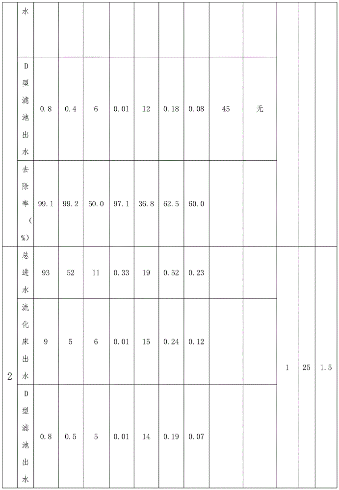
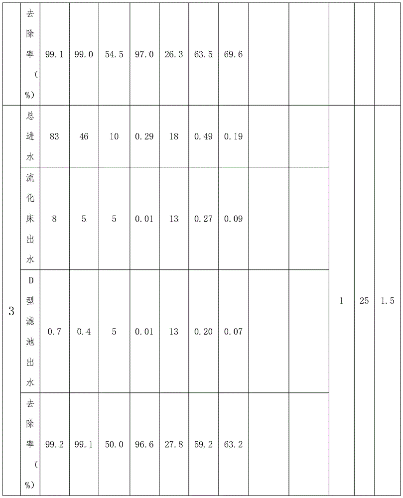
it is worth to say that the water purification station system does not need to treat sewage for many times, so that energy is saved and consumption is reduced; by arranging the flocculation device, the fluidized bed sedimentation tank and the D-type filter tank, the occupied area is reduced by more than 30%, the rising flow rate of the fluidized bed sedimentation tank can be 15-20m/h, the rising flow rate of the common inclined tube/inclined plate sedimentation tank is 6-9m/h, the filtering speed of the D-type filter tank can be 15-18m/h, and the filtering speed of the common V-type filter tank is 6-8m/h; the backwashing water consumption rate of the D-type filter tank is 0.2-0.3%, and the backwashing water consumption rate of the commonly used V-type filter tank is 1.5-2%, so that the water and the energy are saved; the D-type filter adopts the latest secondary balance water and gas distribution device, so that the water and gas distribution is very uniform, the single area can be 200 square meters, namely the daily water yield of the single pond can reach 7 ten thousand tons/day, and the sewage treatment efficiency is high; the system is used for purifying suspended matters (the removal rate is > 98%), turbidity (the removal rate is > 99%), COD (the removal rate is > 50%), total phosphorus (the removal rate is > 90%), chromaticity (the removal rate is > 35%), heavy metals (the removal rate is > 45%), iron (the removal rate is > 40%), manganese (the removal rate is > 40%), bacteria (the removal rate is > 99%), and escherichia coli (the removal rate is > 99%); pilot data for a particular water purification station system is as follows:
water purification station apparatus pilot unit: (mg/L)

The complete workflow of the utility model may be: the sewage in the raw water tank 1 is pumped into a flocculation device through a raw water lifting pump 8, purified water is obtained after the sewage flocculation device and a fluidized bed sedimentation tank 2 are treated, the purified water enters a water inlet channel 37, then the water in the water inlet channel 37 flows through a material leakage preventing device 32, a self-adaptive filter material device 33, a pebble cushion layer 34 and a secondary water distribution gas device 35 to be purified, the purified water enters a backwashing water inlet channel, the purified water is firstly discharged into a water seal tank through a water outlet pipe, then is discharged into a clean water tank from the water seal tank, the purified water in the clean water tank is conveyed into a water supply pipeline of a user through a water supply pump,
after the purification is finished, backwashing is carried out, a backwashing lifting pump 12 and a backwashing fan 11 are opened, clean water in a clean water tank and gas in the backwashing fan 11 enter a water inlet channel through a backwashing pipe, then enter a secondary water and gas distribution device 35 through a filtering pipe 42, then sequentially enter a secondary water and gas distribution device 35, a pebble cushion layer 34, a self-adaptive filter material device 33 and a material leakage prevention device 32, enter a backwashing drainage channel 38, and are discharged to a mud storage tank through a pipeline.
The foregoing description of embodiments of the utility model has been presented for purposes of illustration and description, and is not intended to be exhaustive or limited to the embodiments disclosed. Many modifications and variations will be apparent to those of ordinary skill in the art without departing from the scope and spirit of the various embodiments described. The terminology used herein was chosen in order to best explain the principles of the embodiments, the practical application, or the technical improvements in the marketplace, or to enable others of ordinary skill in the art to understand the embodiments disclosed herein.
Claims (8)
1. A water purification station system, characterized by: comprises a raw water tank (1), a flocculation device, a fluidized bed sedimentation tank (2), a D-type filter tank (3), a water seal tank (4) and a clean water tank (5) which are connected in sequence through pipelines;
the flocculation device is fixed on the outer side wall of the fluidized bed sedimentation tank (2), the flocculation device is communicated with the fluidized bed sedimentation tank (2) through a pipeline, and raw water enters the fluidized bed sedimentation tank to realize the separation of mud and water after the flocculation device performs flocculation treatment;
the sediment outlet end of the fluidized bed sedimentation tank (2) is also connected with a mud storage tank (7); the clean water outlet end of the fluidized bed sedimentation tank (2) is connected with the water inlet of the D-shaped filter tank (3) through a pipeline, a backwash air inlet pipe (10) is connected with the backwash air inlet end of the D-shaped filter tank (3), and the backwash water outlet end of the D-shaped filter tank (3) is communicated with the inlet end of the mud storage tank (7) through a pipeline;
the device is characterized in that a backwashing air inlet pipe (10) is arranged on the D-shaped filter tank (3), a backwashing fan (11) is arranged on the backwashing air inlet pipe (10), a clear water pipe is arranged between the D-shaped filter tank (3) and the clear water tank (5), a clear water outlet end of the D-shaped filter tank (3) is communicated with an inlet end of the clear water tank (5) through the clear water pipe, a backwashing pipe is arranged on the clear water pipe, and a backwashing water pump (12) is arranged on the backwashing pipe; a water supply pipe is arranged outside the clean water tank (5), the outlet end of the clean water tank (5) is communicated with an external water supply device through a pipeline, and a water supply pump (13) is arranged on the water supply pipe;
the disinfection dosing device (14) is arranged outside the clean water tank (5), and the inlet end of the clean water tank (5) is also connected with the disinfection dosing device (14) through a pipeline.
2. A water purification station system as recited in claim 1, wherein:
the flocculation device comprises a mixer (21), and a coagulation-assisting and dosing device (22) and a flocculation and dosing device (23) are arranged outside the mixer (21);
the fluidized bed sedimentation tank (2) comprises a filter tank body, wherein a water collecting tank (24), a mud-water separator (25), a reactor (26) and a mud discharging layer (27) are sequentially and fixedly connected between the inner side walls of the filter tank body from top to bottom, and the mud discharging layer (27) is positioned at the bottom of the fluidized bed sedimentation tank (2);
a sludge discharge pipe is connected to the side wall of the sludge discharge layer (27), the sludge discharge layer (27) is communicated with the sludge storage tank (7) through the sludge discharge pipe, and a sludge pump is arranged on the sludge discharge pipe;
the coagulation-assisting and dosing device (22) and the flocculation-dosing device (23) are communicated with the water inlet of the mixer (21) through pipelines, the water outlet of the mixer (21) is communicated with the water inlet of the reactor (26) through pipelines, the water outlet of the reactor (26) is connected with the water inlet of the mud-water separator (25) for realizing mud-water separation, and the water outlet of the mud-water separator (25) is communicated with the water inlet of the water collecting tank (24) through pipelines for storing purified water; the water outlet of the water collecting tank (24) is communicated with the D-shaped filter tank (3) through a pipeline.
3. A water purification station system as recited in claim 2, wherein:
the fluidized bed sedimentation tank (2) and the reactor (26) are arranged between the fluidized bed sedimentation tank and the reactor (26), the connecting block (6) is a cuboid connecting block, and the fluidized bed sedimentation tank (2) and the reactor (26) are fixedly connected through the connecting block (6).
4. A water purification station system as recited in claim 2, wherein:
the mud-water separator (25) is a circular separator, a plurality of first holes are uniformly distributed on the circular separator, and the first holes are distributed in a honeycomb shape.
5. A water purification station system as recited in claim 2, wherein:
the mixer (21) comprises: a reaction box and a plurality of bulges;
the bulges are fixedly connected with the two opposite side walls inside the reaction box, and the bulges are arranged in a staggered manner; the water outlet of the mixer (21) is positioned at the bottom of the reaction box, and the water inlet of the mixer (21) is close to the top of the reaction box.
6. A water purification station system as recited in claim 2, wherein:
the D-shaped filter tank (3) comprises: a filter body (31) and a secondary water and gas distribution device (35);
the filter is characterized in that an anti-material-running device (32), a self-adaptive filter material layer (33), a pebble cushion layer (34) and a primary water and gas distribution device (36) are sequentially and fixedly arranged between the inner side walls of the filter body (31) from top to bottom, and the primary water and gas distribution device (36) is positioned at the bottom of the filter body (31);
a water inlet channel (37) and a backwash drainage channel (38) are fixedly arranged on the inner side wall of the filter body (31), the water inlet channel (37) is positioned above the material leakage preventing device (32), the backwash drainage channel (38) is positioned between the side wall of the filter body (31) and the side wall of the material leakage preventing device (32), and a port of the backwash drainage channel (38) is higher than the upper surface of the material leakage preventing device (32); the water inlet channel (37) and the backwash water outlet channel (38) are respectively positioned at two opposite sides of the filter body (31);
the water outlet of the water collecting tank (24) is communicated with the water inlet channel (37) through a pipeline;
the water outlet of the backwash drainage channel (38) is communicated with the mud storage tank (7) through a pipeline;
a backwashing water inlet channel is arranged in the primary water and gas distribution device (36); one end of the secondary water and gas distribution device (35) stretches into the pebble cushion layer (34), and the other end stretches into the backwash water inlet channel; the backwash water inlet channel is communicated with the clean water tank (5) through a backwash pipe, and the backwash water inlet channel is communicated with the water seal tank (4) through a clean water pipe.
7. A water purification station system as recited in claim 6 wherein:
the secondary water and gas distribution device (35) comprises: a primary air cushion layer (40) and a secondary air cushion layer (41), and a filter tube (42) is arranged between the primary air cushion layer (40) and the secondary air cushion layer (41);
the upper end of the filter tube (42) is communicated with the secondary air cushion layer (41), and the lower end of the filter tube (42) is communicated with the primary air cushion layer (40);
the filter tube (42) is provided with a strip-shaped hole (43) and an air inlet hole (44); the strip-shaped hole (43) is positioned at the lower end of the filter tube (42), and the air inlet hole (44) is positioned at the upper end of the strip-shaped hole (43);
the secondary air cushion layer (41) is positioned inside the pebble cushion layer (34), and the primary air cushion layer (40) is positioned inside the backwash water inlet channel.
8. A water purification station system as recited in claim 7, wherein:
the primary air cushion layer (40) is rectangular in shape, and the secondary air cushion layer (41) is triangular in shape.
Priority Applications (1)
| Application Number | Priority Date | Filing Date | Title |
|---|---|---|---|
| CN202223031490.0U CN219136576U (en) | 2022-11-15 | 2022-11-15 | Water purification station system |
Applications Claiming Priority (1)
| Application Number | Priority Date | Filing Date | Title |
|---|---|---|---|
| CN202223031490.0U CN219136576U (en) | 2022-11-15 | 2022-11-15 | Water purification station system |
Publications (1)
| Publication Number | Publication Date |
|---|---|
| CN219136576U true CN219136576U (en) | 2023-06-06 |
Family
ID=86596768
Family Applications (1)
| Application Number | Title | Priority Date | Filing Date |
|---|---|---|---|
| CN202223031490.0U Active CN219136576U (en) | 2022-11-15 | 2022-11-15 | Water purification station system |
Country Status (1)
| Country | Link |
|---|---|
| CN (1) | CN219136576U (en) |
-
2022
- 2022-11-15 CN CN202223031490.0U patent/CN219136576U/en active Active
Similar Documents
| Publication | Publication Date | Title |
|---|---|---|
| CN103435235B (en) | Kitchen waste filtrate treatment equipment and method | |
| CN101205109B (en) | Apparatus for treating chemical fiber waste water by anaerobic method | |
| CN203613071U (en) | Sewage treatment device | |
| CN204874123U (en) | Quality of water clean system | |
| CN102107968A (en) | Water purification system and water purification method of flotation filter tank | |
| CN205709927U (en) | A kind of vertical eddy current idetified separation device and high efficient solid and liquid separation granulating fluidized bed | |
| CN213977269U (en) | Rural drinking water filtration system | |
| CN201292300Y (en) | Water producing and desalting integrated treatment apparatus for oil field | |
| CN111392964B (en) | Method and device for treating sewage of rain and sewage combined pump station | |
| CN210764434U (en) | Dissolved air flotation device | |
| CN218910103U (en) | Chemical precipitation adsorption device for treating high fluoride wastewater | |
| CN219136576U (en) | Water purification station system | |
| CN207738510U (en) | A kind of anaerobic baffle plate return-flow system | |
| CN201154935Y (en) | Chemical fabrics waste water treatment plant | |
| CN203346197U (en) | Integrated water purification device | |
| CN103508557B (en) | Active sludge bed reaction treatment method and device | |
| CN219136575U (en) | Sewage zero discharge system of water purification station | |
| CN206232523U (en) | Integrated sewage treating apparatus | |
| CN211226820U (en) | Compact and efficient oil removing device for offshore platform production wastewater | |
| CN210796117U (en) | Environment-friendly wastewater treatment and purification device | |
| CN212076761U (en) | Container type integrated sewage treatment equipment | |
| CN211226811U (en) | Integrated sewage treatment equipment | |
| CN209210490U (en) | A kind of adjustable multistage AO-MBBR process spent water processing unit of series | |
| CN104860469A (en) | Oil refining sewage integrated combination treatment system and oil refining sewage integrated combination treatment method | |
| CN109292980A (en) | A kind of adjustable multistage AO-MBBR process spent water processing unit of series and method |
Legal Events
| Date | Code | Title | Description |
|---|---|---|---|
| GR01 | Patent grant | ||
| GR01 | Patent grant |