CN219117000U - Turning device for prefabricated component in tunnel - Google Patents
Turning device for prefabricated component in tunnel Download PDFInfo
- Publication number
- CN219117000U CN219117000U CN202320051191.9U CN202320051191U CN219117000U CN 219117000 U CN219117000 U CN 219117000U CN 202320051191 U CN202320051191 U CN 202320051191U CN 219117000 U CN219117000 U CN 219117000U
- Authority
- CN
- China
- Prior art keywords
- upright post
- upright
- tunnel
- turnover device
- electric hoist
- Prior art date
- Legal status (The legal status is an assumption and is not a legal conclusion. Google has not performed a legal analysis and makes no representation as to the accuracy of the status listed.)
- Active
Links
Images


Classifications
-
- Y—GENERAL TAGGING OF NEW TECHNOLOGICAL DEVELOPMENTS; GENERAL TAGGING OF CROSS-SECTIONAL TECHNOLOGIES SPANNING OVER SEVERAL SECTIONS OF THE IPC; TECHNICAL SUBJECTS COVERED BY FORMER USPC CROSS-REFERENCE ART COLLECTIONS [XRACs] AND DIGESTS
- Y02—TECHNOLOGIES OR APPLICATIONS FOR MITIGATION OR ADAPTATION AGAINST CLIMATE CHANGE
- Y02E—REDUCTION OF GREENHOUSE GAS [GHG] EMISSIONS, RELATED TO ENERGY GENERATION, TRANSMISSION OR DISTRIBUTION
- Y02E10/00—Energy generation through renewable energy sources
- Y02E10/20—Hydro energy
Landscapes
- Lining And Supports For Tunnels (AREA)
Abstract
The utility model discloses a turnover device for prefabricated components in a tunnel, and aims to solve the technical problems that the existing turnover mode is labor-consuming and high in cost. The turnover device mainly comprises a base, a first upright post and a second upright post, wherein the first upright post and the second upright post are arranged on the base; a plurality of supporting beams are arranged between the first upright post and the second upright post, mounting plates are arranged at the tops of the first upright post and the second upright post, and electric hoist is arranged on the mounting plates; the first upright post and the second upright post are provided with cantilevers in an extending mode, and pulley blocks corresponding to the electric hoist are mounted on the cantilevers. The two sides of the first upright post and the second upright post are respectively provided with a second inclined strut for improving stability, and the second inclined struts are supported on the ground through supporting plates so as to improve the supporting capacity of the second inclined struts. The utility model provides a through set up electric block on first stand and second stand and set up the assembly pulley on the cantilever and assist the upset to prefabricated component, and then improved prefabricated component's upset efficiency.
Description
Technical Field
The application relates to the technical field of shield tunnel construction auxiliary equipment, in particular to a turnover device for prefabricated components in a tunnel.
Background
Along with the development of engineering science and technology, large-diameter tunnel engineering is more and more, tunnel construction speed is faster and more, and the application development of the full-prefabricated assembly process of the tunnel internal structure is very rapid; the initial stage of the tunnel construction is provided with a duct piece, an arc-shaped (opening) piece and an intermediate wall, and all the ditches, cable grooves, evacuation platforms and the like on the two sides at the later stage need to be assembled and butted in the tunnel after factory prefabrication and molding.
The volume and the weight of the internal components of the large-diameter shield tunnel are increased from the original phi 11.18m to the current diameter phi 16.28 m; auxiliary equipment such as transportation, hoisting, transportation, installation and the like of large prefabricated members slightly cannot keep pace with the development of shield technology, so that the hoisting and assembling equipment with limited operation space in some tunnels is still required to be researched and developed from new designs. The progress and development of shield large-diameter construction technology is severely restricted by the fact that auxiliary equipment does not follow up and update.
After the prefabricated member is transported to a construction site, the prefabricated member of the middle partition wall is particularly required to be transversely rotated for 180 degrees for assembly and butt joint after being transported to the construction site, and at least 45t double-door cranes are required to realize overturning of the prefabricated member due to the large size of the prefabricated member. However, the existing method of rotating by adopting the double-door crane is time-consuming and labor-consuming and has high cost, so that a turnover device for prefabricated components in the tunnel is needed to improve the installation and construction efficiency.
The information disclosed in this background section is only for enhancement of understanding of the background of the disclosure and should not be taken as an acknowledgement or any form of suggestion that this information forms the prior art that is well known to a person skilled in the art.
Disclosure of Invention
The inventor finds based on long-term underground shield construction practice: because prefab is bulky, therefore the mode of current upset adopts two to overturn at least 45 t's gantry crane, but this kind of mode wastes time and energy, and is with high costs, and then leads to tunnel construction period to be tension, through setting up electric block and assembly pulley on first stand and second stand to the upset of supplementary prefab improves upset efficiency.
In view of at least one of the above technical problems, the present disclosure provides a turnover device for a prefabricated member inside a tunnel, by arranging an electric hoist and a pulley block on a first upright and a second upright, so as to assist in turnover of the prefabricated member, thereby improving installation and construction efficiency of the prefabricated member and greatly reducing cost.
According to one aspect of the present disclosure, there is provided a turnover device for a prefabricated member inside a tunnel, including a base, a first column and a second column disposed on the base;
a plurality of supporting beams are arranged between the first upright post and the second upright post, mounting plates are arranged at the tops of the first upright post and the second upright post, and electric hoist is arranged on the mounting plates;
the first upright post and the second upright post are provided with cantilevers in an extending mode, and pulley blocks corresponding to the electric hoist are mounted on the cantilevers.
In some embodiments of the present disclosure, a first diagonal brace is disposed between the cantilever and the first and second uprights.
Through setting up first bracing in order to improve the bearing capacity of cantilever, guarantee connect between first stand, second stand and the cantilever and fasten.
In some embodiments of the present disclosure, a stiffener is disposed between the first upright, the second upright, and the base.
The stability of the first upright post and the second upright post is improved through the reinforcing ribs, and the first upright post, the second upright post and the base are connected and fastened.
In some embodiments of the present disclosure, the electric block is attached to the component clamp by a wire rope.
The electric hoist can effectively ensure that the electric hoist stably lifts the prefabricated part through the steel wire rope hanging component clamp, and ensures the transportation stability of the prefabricated part.
In some embodiments of the disclosure, the two sides of the first upright and the second upright are respectively provided with a second diagonal brace for improving stability, and the second diagonal braces are supported on the ground through a supporting plate so as to improve the supporting capability of the second diagonal braces.
The stability of the first upright post and the second upright post can be further improved by arranging the second diagonal braces on the two sides of the first upright post and the second upright post, and the second diagonal braces are connected to the ground through the supporting plates, so that the supporting capacity of the second diagonal braces can be improved.
In some embodiments of the present disclosure, a threaded hole is provided in the support plate, and a bolt and a nut are installed in the threaded hole to fix the support plate.
The supporting plate is detachably fixed on the ground through the bolts and the nuts, so that the connection tightness between the second diagonal bracing and the ground is ensured, and the supporting capacity of the second diagonal bracing is improved.
One or more technical solutions provided in the embodiments of the present application at least have the following technical effects or advantages:
1. the utility model provides a through set up electric block on first stand and second stand and set up smart assembly pulley on the cantilever and assist the upset to prefabricated component, improved prefabricated component's upset efficiency effectively.
2. The second diagonal braces are arranged on the two sides of the first upright post and the second upright post, so that the stability of the first upright post and the second upright post can be effectively guaranteed, and the turnover efficiency and the safety of the prefabricated component can be improved.
Drawings
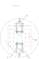
Fig. 1 is a schematic structural diagram of an embodiment of the present application.
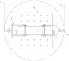
FIG. 2 is a second schematic structural view of an embodiment of the present application.
Fig. 3 is a schematic state one of the working process according to an embodiment of the present application.
Fig. 4 is a schematic state two of the working process according to an embodiment of the present application.
Fig. 5 is a schematic view of a third working process according to an embodiment of the present application.
Fig. 6 is a schematic state four of the working process according to an embodiment of the present application.
Fig. 7 is a schematic state five of the working process according to an embodiment of the present application.
In the above figures, 1 is a base, 2 is a first upright, 21 is a second diagonal bracing, 22 is a supporting plate, 23 is a bolt, 24 is a second upright, 25 is a reinforcing rib, 28 is a supporting cross beam, 3 is a cantilever, 4 is a first diagonal bracing, 5 is an electric hoist, 6 is a pulley block, 7 is a steel wire rope, 8 is a component clamp, 9 is a mounting plate, and 10 is a prefabricated component.
Detailed Description
In the description of the present application, it should be understood that, if the terms "upper", "lower", "front", "rear", "left", "right", "top", "bottom", "inner", "outer", "vertical", "horizontal", "clockwise", "counterclockwise", etc. are referred to, the orientation or positional relationship indicated based on the drawings are merely for convenience of description of the present application and to simplify the description, and do not indicate or imply that the apparatus or elements referred to must have a specific orientation, be configured and operated in a specific orientation, and thus should not be construed as limiting the present application. Reference to "first," "second," etc. in this application is for distinguishing between the objects described and not necessarily for any sequential or technical purpose. Reference to "connected" and "coupled" in this application includes both direct and indirect connections (couplings), unless specifically stated otherwise.
The unit modules, components, structures, and mechanism devices according to the following examples are commercially available products unless otherwise specified.
According to the overturning device for the prefabricated part in the tunnel, the technical problems that an existing mode of overturning through two 45t gantry cranes is time-consuming and labor-consuming and high in cost are solved, and the overturning efficiency of the prefabricated part is effectively improved by arranging the electric hoist on the first upright post and the second upright post and arranging the pulley block corresponding to the electric hoist on the cantilever.
The technical scheme in this application embodiment is for solving the technical problem that above-mentioned current upset mode is wasted time and energy, and the overall thinking is as follows: through setting up the base and be in set up first stand and second stand on the base, just be provided with a plurality of supporting beams between first stand and the second stand, the top of first stand and second stand is provided with the mounting panel, install electric block on the mounting panel, extend on first stand and the second stand and be provided with the cantilever, install on the cantilever with the assembly pulley that electric block corresponds, through electric block with the upset of prefabricated component is carried out in the cooperation of assembly pulley.
Above-mentioned first stand, second stand's both sides all are provided with the second bracing that is used for improving the steadiness, the second bracing is supported in ground through the backup pad to improve its bearing capacity, be provided with the screw hole in the backup pad, threaded hole installs bolt and nut and fixes, through improving the stability of first stand and second stand, and then is favorable to prefabricated component's upset operation.
For better understanding of the technical solutions of the present application, the following detailed description will refer to the accompanying drawings and specific embodiments.
Example 1
The embodiment discloses a turnover device for prefabricated parts in a tunnel, referring to fig. 1 and 2, mainly comprising a base 1, a first upright post 2 and a second upright post 24 which are arranged on the base 1; a plurality of supporting beams 28 are arranged between the first upright 2 and the second upright 24, mounting plates 9 are arranged at the tops of the first upright 2 and the second upright 24, and electric hoist 5 is mounted on the mounting plates 9.
The cantilever 3 is arranged on the first upright post 2 and the second upright post 24 in an extending manner, the pulley block 6 corresponding to the electric hoist 5 is arranged on the cantilever 3, in addition, the electric hoist 5 is arranged on the pulley block 6 in a penetrating manner through the steel wire rope 7 in a hanging manner, the component clamps 8 clamp the prefabricated components 10 for overturning, the number of the electric hoist 5 is at least two, the specific number of the electric hoist can be set according to the actual construction conditions, the electric hoist 5 can effectively ensure the stable lifting prefabricated components 10 of the electric hoist 5 through the steel wire rope 7 hanging the component clamps 8, and the stability of the prefabricated components 10 is ensured.
In addition, a first diagonal brace 4 is arranged between the cantilever 3 and the first upright 2 and the second upright 24, and a reinforcing rib 25 is arranged between the first upright 2 and the second upright 24 and the base 1. By arranging the first diagonal bracing 4 to improve the supporting capacity of the cantilever 3, the connection and fastening between the first upright post 2, the second upright post 24 and the cantilever 3 are ensured. The stability of the first upright post 2 and the second upright post 24 is improved by arranging the reinforcing ribs 25, and the first upright post 2, the second upright post 24 and the base 1 are connected and fastened.
Further, the two sides of the first upright 2 and the second upright 24 are respectively provided with a second diagonal brace 21 for improving stability, and the second diagonal braces 21 are supported on the ground through support plates 22 so as to improve the supporting capability thereof. The supporting plate 22 is provided with a threaded hole, and a bolt 23 and a nut are installed in the threaded hole to fix the threaded hole. The stability of the first upright 2 and the second upright 24 can be further improved by arranging the second diagonal braces 21 on both sides of the first upright 2 and the second upright 24, and the second diagonal braces 21 are connected to the ground through the support plates 22, so that the supporting capability of the second diagonal braces 21 can be improved. And the supporting plate 22 is detachably fixed on the ground through bolts 23 and nuts, so that the connection tightness between the second diagonal bracing 21 and the ground is ensured, and the supporting capacity of the second diagonal bracing is further improved.
As shown in fig. 3 to 7, in order to turn over the prefabricated part 10 by using the device, two devices are used to turn over, one device clamps the upper part of the prefabricated part 10, the other device clamps the lower part of the prefabricated part 10 to turn over the prefabricated part 10, the electric hoist 5 passes through the steel wire rope 7 and is arranged in the pulley block 6 in a penetrating manner, and the prefabricated part 10 is clamped by the component clamp 8 at the tail end of the steel wire rope 7 so as to turn over the prefabricated part 10.
While certain preferred embodiments of the present application have been described, additional variations and modifications in those embodiments may occur to those skilled in the art once they learn of the basic inventive concepts. It is therefore intended that the following claims be interpreted as including the preferred embodiments and all such alterations and modifications as fall within the scope of the application.
It will be apparent to those skilled in the art that various modifications and variations can be made in the present application without departing from the spirit and scope of the utility model of the present application. Thus, if such modifications and variations of the present application fall within the scope of the claims and the equivalents thereof, the present application is intended to cover such modifications and variations.
Claims (6)
1. The turnover device for the prefabricated component in the tunnel is characterized by comprising a base, a first upright post and a second upright post, wherein the first upright post and the second upright post are arranged on the base;
a plurality of supporting beams are arranged between the first upright post and the second upright post, mounting plates are arranged at the tops of the first upright post and the second upright post, and electric hoist is arranged on the mounting plates;
the first upright post and the second upright post are provided with cantilevers in an extending mode, and pulley blocks corresponding to the electric hoist are mounted on the cantilevers.
2. The turnover device for tunnel interior prefabricated parts according to claim 1, wherein a first diagonal brace is provided between the cantilever and the first and second columns.
3. The turnover device for tunnel interior prefabricated parts according to claim 1, wherein reinforcing ribs are provided between the first upright, the second upright and the base.
4. The turnover device for tunnel interior prefabricated parts according to claim 1, wherein the electric hoist is hung on a part fixture by a wire rope.
5. The turnover device for tunnel interior prefabricated parts according to claim 1, wherein the first and second upright posts are provided with second diagonal braces on both sides thereof for improving stability, and the second diagonal braces are supported on the ground by support plates for improving supporting ability thereof.
6. The turnover device for tunnel interior prefabricated parts according to claim 5, wherein screw holes are formed in the support plate, and bolts and nuts are installed in the screw holes to fix the support plate.
Priority Applications (1)
| Application Number | Priority Date | Filing Date | Title |
|---|---|---|---|
| CN202320051191.9U CN219117000U (en) | 2023-01-09 | 2023-01-09 | Turning device for prefabricated component in tunnel |
Applications Claiming Priority (1)
| Application Number | Priority Date | Filing Date | Title |
|---|---|---|---|
| CN202320051191.9U CN219117000U (en) | 2023-01-09 | 2023-01-09 | Turning device for prefabricated component in tunnel |
Publications (1)
| Publication Number | Publication Date |
|---|---|
| CN219117000U true CN219117000U (en) | 2023-06-02 |
Family
ID=86521393
Family Applications (1)
| Application Number | Title | Priority Date | Filing Date |
|---|---|---|---|
| CN202320051191.9U Active CN219117000U (en) | 2023-01-09 | 2023-01-09 | Turning device for prefabricated component in tunnel |
Country Status (1)
| Country | Link |
|---|---|
| CN (1) | CN219117000U (en) |
-
2023
- 2023-01-09 CN CN202320051191.9U patent/CN219117000U/en active Active
Similar Documents
| Publication | Publication Date | Title |
|---|---|---|
| CN103510541A (en) | Device and method for installing steel pipe column to interior of lifting frame hole | |
| CN114059758A (en) | Assembled double-layer integral elevator shaft platform | |
| CN207268073U (en) | Novel flexible formwork bearing frame | |
| CN219117000U (en) | Turning device for prefabricated component in tunnel | |
| CN111852074B (en) | Adjustable lifting type supporting device | |
| CN202785387U (en) | Indoor cantilever crane | |
| CN216512520U (en) | Lifting system suitable for small space | |
| CN216713950U (en) | Steel construction assembled supports bed-jig | |
| CN213484787U (en) | Photovoltaic power generation board mounting and supporting structure with suspended steel beam foundation | |
| CN111525487A (en) | Utility tunnel self-supporting pipeline support | |
| CN220432105U (en) | Turning device for prefabricated part in tunnel | |
| CN218931529U (en) | Lifting device for column top steel beam | |
| JPH0754494A (en) | Temporary shed | |
| CN217538057U (en) | Detachable assembled protective shed | |
| CN117027164B (en) | Dry-type connecting node for beam column of assembled concrete frame and connecting method thereof | |
| CN219709023U (en) | Steel corridor hydraulic lifting platform | |
| CN212027790U (en) | Reusable shield starting reaction frame | |
| CN219973857U (en) | Super high parapet does not have counter weight hanging flower basket suspension | |
| CN219826200U (en) | Supplementary installation device of steel-pipe column ring beam steel reinforcement cage | |
| CN216737302U (en) | Special tower crane for additionally installing elevator | |
| CN220081500U (en) | Small-section tunnel excavation self-moving type foldable trolley | |
| CN212129861U (en) | Overhanging scaffold for construction engineering | |
| CN219604158U (en) | High-altitude welding operation platform for bridge arch installation | |
| CN217782808U (en) | Hanging basket support for installing tower crown structure of building | |
| CN115596247B (en) | Inclined-pulling type full-column dismantling and transferring operation frame and construction method thereof |
Legal Events
| Date | Code | Title | Description |
|---|---|---|---|
| GR01 | Patent grant | ||
| GR01 | Patent grant |