CN219103602U - Efficient oven for fabric dyeing machine - Google Patents
Efficient oven for fabric dyeing machine Download PDFInfo
- Publication number
- CN219103602U CN219103602U CN202223302362.5U CN202223302362U CN219103602U CN 219103602 U CN219103602 U CN 219103602U CN 202223302362 U CN202223302362 U CN 202223302362U CN 219103602 U CN219103602 U CN 219103602U
- Authority
- CN
- China
- Prior art keywords
- fabric
- flattening
- dyeing machine
- roller
- fabric dyeing
- Prior art date
- Legal status (The legal status is an assumption and is not a legal conclusion. Google has not performed a legal analysis and makes no representation as to the accuracy of the status listed.)
- Active
Links
Images


Classifications
-
- Y—GENERAL TAGGING OF NEW TECHNOLOGICAL DEVELOPMENTS; GENERAL TAGGING OF CROSS-SECTIONAL TECHNOLOGIES SPANNING OVER SEVERAL SECTIONS OF THE IPC; TECHNICAL SUBJECTS COVERED BY FORMER USPC CROSS-REFERENCE ART COLLECTIONS [XRACs] AND DIGESTS
- Y02—TECHNOLOGIES OR APPLICATIONS FOR MITIGATION OR ADAPTATION AGAINST CLIMATE CHANGE
- Y02P—CLIMATE CHANGE MITIGATION TECHNOLOGIES IN THE PRODUCTION OR PROCESSING OF GOODS
- Y02P70/00—Climate change mitigation technologies in the production process for final industrial or consumer products
- Y02P70/50—Manufacturing or production processes characterised by the final manufactured product
- Y02P70/62—Manufacturing or production processes characterised by the final manufactured product related technologies for production or treatment of textile or flexible materials or products thereof, including footwear
Abstract
The utility model discloses a high-efficiency oven for a fabric dyeing machine, which comprises a frame, guide rollers, a drying box, a control panel and a leveling device. According to the utility model, by arranging the flattening device, when the fabric passes through the flattening device, the fabric can be placed on the surfaces of the two flattening rollers and is attached to the surfaces of the flattening threads, the biaxial motor is started to enable the two flattening rollers to rotate so as to enable the flattening threads to rotate, and the fabric stretches under the action of the rotating flattening threads, so that folds in the fabric can be pulled out in the process, the elimination of the folds is realized, the manual arrangement is not needed, the workload of staff is reduced, the arrangement effect is also improved, and the efficiency of removing the folds is higher; through being equipped with pushing down the structure, when the fabric is located between two pushing down the roller, the pushing down roller of upper end pushes down and pastes in the fabric surface, has realized that the pushing down roller of upper end pastes in the fabric surface all the time, and has promoted and has pushed down the effect.
Description
Technical Field
The utility model relates to the field of baking ovens, in particular to a high-efficiency baking oven for a fabric dyeing machine.
Background
The fabric is a flat soft piece formed by intersecting, winding and connecting fine and soft objects, the woven fabric is formed by yarns with intersecting relation, the knitted fabric is formed by yarns with winding relation, the non-woven fabric is formed by yarns with connecting relation, the third fabric is formed by yarns with intersecting/winding relation, and dyeing treatment is needed in the production process for improving the attractive appearance of the fabric, so that a dyeing machine is needed, quick drying is needed after dyeing by the dyeing machine, and an oven is needed at the moment.
The prior patent: CN212175235U discloses a fabric dyeing, drying and shaping device, comprising a feed inlet, a dyeing mechanism, a flattening mechanism, a drying and shaping mechanism and a discharge outlet; the dyeing mechanism is arranged at one side of the feeding roller and comprises a dyeing chamber, a first cylinder, a first dyeing roller, a second dyeing roller and a transition roller; the flattening mechanism is arranged at the lower part of the dyeing mechanism and comprises a flattening chamber, a plurality of heating rollers and a tensioning mechanism; the drying and shaping mechanism is arranged on one side, far away from the feed inlet, of the dyeing mechanism and the flattening mechanism, and comprises a drying chamber, a plurality of transfer rollers, a first drying mechanism and a second drying mechanism. The utility model aims to provide a fabric dyeing, drying and shaping device, which integrates dyeing, drying and shaping, solves the technical problems that the drying effect is poor due to uneven heating of two surfaces of a fabric in the prior art, folds are easily generated on the surface of the fabric in the drying process, the quality of a finished product is influenced, the drying and shaping effects are improved, and the quality of the finished product of the fabric is ensured.
The above-mentioned patents or existing ovens have the following problems:
when the fabric is placed on the oven after being dyed, the fabric is usually wrinkled due to the fact that the fabric contains the coloring agent, and therefore the wrinkled fabric needs to be manually tidied, and accordingly the fabric with the wrinkled is prevented from being deformed after being dried, but the manual tidying efficiency is low, all the wrinkled cannot be considered, and the workload of workers is increased.
Disclosure of Invention
Accordingly, in order to address the above-described deficiencies, the present utility model provides an efficient oven for a fabric dyeing machine.
In order to achieve the above purpose, the present utility model adopts the following technical scheme: the utility model provides a high-efficient oven for fabric dyeing machine, includes the frame, be equipped with the deflector roll in the frame, be equipped with the stoving case in the frame to be equipped with control panel at the surface of stoving case, be equipped with the device of pushing away the flat in the frame, the device of pushing away the flat includes the riser, the riser is located the frame surface, is equipped with biax motor at the surface of riser, the transfer line that is connected with biax motor output shaft, the transfer line stretches into inside the machine box and is connected rather than inside worm, with worm wheel that the worm is connected to run through at the middle part of worm wheel has the dwang, and the dwang is located and is pushed away flat roller one end surface.
Preferably, a second vertical plate is arranged on the top end face of the frame, the second vertical plate and the vertical plate are in the same straight line, and the other end of the pushing roller is rotationally connected with the second vertical plate.
Preferably, the surface of the flattening roller is provided with flattening threads, and the flattening threads are provided with two and symmetrically arranged at the front end and the rear end of the flattening roller.
Preferably, the two leveling rollers are arranged at the upper end and the lower end of the vertical plate, have the same structure, and are respectively connected with the output shafts at the two ends of the double-shaft motor.
Preferably, the pushing structure comprises a sliding block, a rotating rod of the pushing roller at the upper end penetrates through the middle of the sliding block, the sliding block is in sliding connection with the slideway, a sliding plate is arranged on the side wall of the sliding block, and a spring is arranged at the upper end of the sliding plate.
Preferably, the adjusting structure comprises a knob, the knob is arranged at the end part of the upright post, a threaded rod is arranged at the middle part of the upright post, a thread bush connected with the threaded rod is arranged at the middle part of the adjusting plate in a sleeved mode.
Preferably, the vertical plate is internally provided with limit bars, and the limit bars are not less than four and are evenly distributed in the vertical plate.
Preferably, the edge of the adjusting plate is provided with a sliding opening, and the sliding opening is connected with the surface of the limit strip in a sliding manner.
The utility model has the beneficial effects that:
according to the utility model, by arranging the flattening device, when the fabric passes through the flattening device, the fabric can be placed on the surfaces of the two flattening rollers and is attached to the surfaces of the flattening threads, the biaxial motor is started to enable the two flattening rollers to rotate so as to enable the flattening threads to rotate, and the fabric stretches under the action of the rotating flattening threads, so that folds in the fabric can be pulled out in the process, the effect of eliminating the folds without manual arrangement is achieved, the workload of staff is reduced, meanwhile, the arrangement effect is also improved, and the efficiency of removing the folds is higher.
Further, through being equipped with pushing down the structure, when the fabric is located between two pushing down the roller, the pushing down roller of upper end pushes down and pastes in the fabric surface, has realized that the pushing down roller of upper end pastes in the fabric surface all the time, and has promoted and has pushed down the flat effect.
Further, through being equipped with adjusting structure, rotate the knob and adjust the spring force, reached and adjusted the spring force of spring, avoid the upper end to push away the flat roller down the pressure degree relatively poor and can't effectually push away the fold flat.
Drawings
FIG. 1 is a schematic diagram of the structure of the present utility model;
FIG. 2 is a schematic diagram of a pushing device according to the present utility model;
FIG. 3 is a schematic cross-sectional elevation view of the cartridge of the present utility model;
FIG. 4 is a schematic view of a front cross-sectional structure of a riser of the present utility model;
fig. 5 is a schematic top view of the regulator plate of the present utility model.
Wherein: the device comprises a frame-1, guide rollers-2, a drying box-3, a control panel-4, a leveling device-5, a vertical plate-51, a double-shaft motor-52, a transmission rod-53, a machine box-54, a worm-55, a worm wheel-56, a rotating rod-57, a leveling roller-58, a second vertical plate-511, leveling threads-581, a telescopic transmission shaft-521, a pressing structure-59, an adjusting structure-510, a sliding block-591, a sliding way-592, a sliding plate-593, a spring-594, a knob-5101, a stand column-5102, a threaded rod-5103, a threaded sleeve-5104, an adjusting plate-5105, a limit bar-5106 and a sliding port-5107.
Detailed Description
In order to further explain the technical scheme of the utility model, the following is explained in detail through specific examples.
Referring to fig. 1 and 2, the present utility model provides a high-efficiency oven for a fabric dyeing machine, comprising a frame 1, wherein a guide roller 2 is disposed in the frame 1, the guide roller 2 is rotatably connected with the frame 1, a drying box 3 is mounted on the top of the frame 1 through bolts, a control panel 4 is mounted on the front surface of the drying box 3, and the control panel 4 is electrically connected with the drying box 3 and electrically connected with a flattening device 5 disposed at the left end of the top of the frame 1.
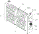
Referring to fig. 1, 2, 3 and 4, the present utility model provides a high efficiency oven for a fabric dyeing machine, the leveling device 5 comprises a vertical plate 51, the vertical plate 51 is mounted at the left end of the top end surface of the frame 1 by bolts, a second vertical plate 511 is mounted on the opposite surface of the vertical plate 51, a double-shaft motor 52 is mounted at the middle end of the front side of the vertical plate 51 by bolts, the lower end output shaft of the double-shaft motor 52 is butted with one end of a transmission rod 53, the upper end output shaft of the double-shaft motor 52 is butted with one end of a telescopic transmission shaft 521, two boxes 54 are arranged at the front side of the vertical plate 51 and respectively positioned at the upper end and the lower end of the front side of the vertical plate 51, the transmission rod 53 penetrates through the top end surface of the lower end box 54 and is rotatably connected with the lower end surface of the upper end box 54, the telescopic transmission shaft 521 penetrates through the bottom end surface of the upper end box 54 and is rotatably connected with the upper end surface, a worm 55 and a worm gear 56 are arranged in the two boxes 54, the worm 55 and the worm wheel 56 are in meshed connection, the worm 55 is in rotary connection with the machine box 54 so as to realize the fixation of the worm 55, the lower end of the transmission rod 53 is connected with the worm 55 in the lower machine box 54, the upper end of the telescopic transmission shaft 521 is connected with the worm 55 in the upper machine box 54 so as to realize the connection of the double-shaft motor 52 with the worm 55 in the upper machine box 54 and synchronous transmission and drive the worm wheel 56 to rotate, the middle parts of the worm wheels 56 in the two machine boxes 54 are penetrated by rotary rods 57, the front ends of the rotary rods 57 are in rotary connection with the machine box 54, the rear ends of the rotary rods 57 are integrally formed with the front ends of the leveling rollers 58, the rear ends of the leveling rollers 58 are in rotary connection with the second vertical plates 511 so as to realize the support for the leveling rollers 58, the surface of the leveling rollers 58 are integrally formed with two leveling threads 581, and the leveling threads 581 are arranged on the surface of the leveling rollers 58 and are symmetrically arranged;
wherein the upper push-down roller 58 is provided with a hold-down structure 59 and an adjustment structure 510.
Referring to fig. 4, the present utility model provides a high efficiency oven for a fabric dyeing machine, the pressing structure 59 includes a sliding block 591, a rotating rod 57 of an upper pushing roller 58 penetrates through the middle of the sliding block 591, the rotating rod 57 is rotationally connected with the sliding block 591, the sliding block 591 is located inside a sliding way 592 and slidingly connected with the sliding way 592, the sliding way 592 is opened at the upper end of the vertical plate 51, a sliding plate 593 is welded at the right side of the sliding block 591, and a spring 594 is arranged at the upper end of the sliding plate 593.
Referring to fig. 4 and 5, the utility model provides a high-efficiency oven for a fabric dyeing machine, the adjusting structure 510 comprises a knob 5101, the knob 5101 is arranged at the upper end of a column 5102, the lower end of the column 5102 penetrates through a sliding plate 593, the sliding plate 593 is in sliding connection with the column 5102 so as to achieve the lifting stability of the sliding plate 593, the vertical plate 5102 is positioned in the middle of a spring 594, bending of the spring 594 is avoided, the lower end of the column 5102 is rotationally connected with the vertical plate 51 so as to achieve the fixing of the column 5102, a threaded rod 5103 is integrally formed in the middle of the column 5102, a threaded sleeve 5104 in threaded connection with the threaded rod 5103 is arranged in the middle of the adjusting plate 5105, the sliding connection is arranged outside the adjusting plate 5105 and is connected with the inner wall of the vertical plate 5105, sliding openings 5107 in sliding connection with the surface of the limiting plate 5106 are formed in the edge of the adjusting plate 5105, the limiting plate 5106 is arranged in the inner side of the limiting plate 5106, the limiting plate 5106 is provided with 4, the limiting plates 5106 can be 5, 6 and the like are not limited in number, the number of the limiting plates 5106 can be assembled together, the number of the limiting plates 5106 can not be adjusted together, and the limiting plate 5106 can be assembled on the bottom end of the adjusting plate 5105.
The working principle is as follows:
the frame 1 is placed in the horizontal position and is located the play cloth end of dyeing machine, then opens stoving case 3 through control panel 4, stoving case 3 can heat, and the staff pulls it earlier after the dyeing machine goes out the fabric end, then winds on deflector roll 2 and push away flat device 5, then passes stoving case 3 to fix the tip of fabric on the rolling machine, the fabric after the rolling machine pulling dyeing, make the fabric remove inside stoving case 3 through deflector roll 2, stoving case 3 can be to carrying out the stoving processing through the fabric, make the fabric realize drying after passing through stoving case 3, thereby realize high-efficient stoving.
When the fabric passes through the leveling device 5, the fabric is placed on the surface of the leveling roller 58 and is attached to the surface of the leveling thread 581, at this time, a worker starts the double-shaft motor 52 through the control panel 4, the output shaft of the double-shaft motor 52 drives the transmission rod 53 and the telescopic transmission shaft 521 to rotate, and then the worm 55 rotates, because the worm 55 is meshed with the worm wheel 56, the worm wheel 56 is driven to rotate when the worm 55 rotates, the worm wheel 56 drives the rotating rod 57, both leveling rollers 58 rotate, the leveling roller 58 drives the leveling thread 581 to rotate when rotating, and the fabric is attached to the leveling thread 581, so that the leveling thread 581 can push the fabric forward and backward at both ends under the rotation of the fabric, the fabric stretches out, wrinkles can be pulled out in the process, the wrinkles can be eliminated, the wrinkles can be processed constantly under the continuous rotation, the convenience of the worker is realized, and the workload of the worker is reduced.
When the fabric is positioned between the two leveling rollers 58, the leveling rollers 58 at the upper end are jacked up to drive the rotating rod 57 to rise, the sliding block 591 is driven to slide along the inner wall of the slideway 592, the sliding block 591 can drive the sliding plate 593 to move upwards in the process, at the moment, the spring 594 is compressed by force to generate elasticity, and the elasticity pushes the sliding plate 593 downwards, so that the leveling rollers 58 at the upper end move downwards to be attached to the surface of the fabric, the effect that the leveling rollers 58 at the upper end are always attached to the surface of the fabric is realized, and the leveling effect is improved.
The knob 5101 is rotated to enable the upright post 5102 and the threaded rod 5103 to rotate, and the threaded sleeve 5104 is in threaded connection with the threaded rod 5103, and the adjusting plate 5105 is limited by the limiting bar 5106, so that when the threaded rod 5103 rotates, the threaded sleeve 5104 and the adjusting plate 5105 can move downwards to compress the spring 594, the elasticity of the spring 594 can be increased after the spring 594 is compressed, the purpose that the elasticity of the spring 594 is adjusted is achieved, and the phenomenon that the pushing roll 58 at the upper end is poor in downward pressure degree and cannot effectively push wrinkles is avoided.
The utility model provides a high-efficiency oven for a fabric dyeing machine, which is provided with a flattening device 5, when a fabric passes through the flattening device 5, the fabric can be placed on the surfaces of two flattening rollers 58 and is attached to the surfaces of flattening threads 581, a double-shaft motor 52 is started to enable the two flattening rollers 58 to rotate so as to enable the flattening threads 581 to rotate, the fabric stretches under the action of the rotating flattening threads 581, folds in the fabric can be pulled out in the process, the effect of eliminating the folds without manual arrangement is achieved, the workload of staff is reduced, meanwhile, the arrangement effect is also improved, and the efficiency of removing the folds is higher; by arranging the pressing structure 59, when the fabric is positioned between the two flattening rollers 58, the flattening roller 58 at the upper end presses downwards to be attached to the surface of the fabric, so that the flattening roller 58 at the upper end is always attached to the surface of the fabric, and the flattening effect is improved; through being equipped with adjusting structure 510, turning knob 5101 adjusts spring 594 elasticity, has reached the elasticity of adjusting spring 594, avoids the push-out roller 58 of upper end to push away the pressure degree relatively poor and can't effectually push away the fold flat.
The foregoing is merely a preferred example of the present utility model, and the present utility model is not limited thereto, but it is to be understood that modifications and equivalents of some of the technical features described in the foregoing embodiments may be made by those skilled in the art, although the present utility model has been described in detail with reference to the foregoing embodiments. Any modification, equivalent replacement, improvement, etc. made within the spirit and principle of the present utility model should be included in the protection scope of the present utility model.
Claims (8)
1. The efficient oven for the fabric dyeing machine comprises a frame (1), wherein a guide roller (2) is arranged in the frame (1), a drying box (3) is arranged on the frame (1), and a control panel (4) is arranged on the surface of the drying box (3);
the method is characterized in that: still include pushing away flat device (5), be equipped with on frame (1) and push away flat device (5), it includes riser (51) to push away flat device (5), riser (51) are located frame (1) surface, are equipped with biax motor (52) on the surface of riser (51), transfer line (53) that are connected with biax motor (52) output shaft, transfer line (53) stretch into inside box (54) and be connected with worm (55) of its inside, with worm wheel (56) that worm (55) are connected to run through at the middle part of worm wheel (56) has dwang (57), and dwang (57) are located and push away flat roller (58) one end surface.
2. A high efficiency oven for a fabric dyeing machine according to claim 1, characterized in that: the top end surface of the frame (1) is provided with a second vertical plate (511), the second vertical plate (511) and the vertical plate (51) are positioned on the same straight line, and the other end of the pushing roll (58) is rotationally connected with the second vertical plate (511).
3. A high efficiency oven for a fabric dyeing machine according to claim 2, characterized in that: the surface of the flattening roller (58) is provided with flattening threads (581), and the flattening threads (581) are provided with two and symmetrically arranged at the front end and the rear end of the flattening roller (58).
4. A high efficiency oven for a fabric dyeing machine according to claim 3 and characterized by: the two pushing rollers (58) are arranged at the upper end and the lower end of the vertical plate (51) and are identical in structure, and are respectively connected with output shafts at the two ends of the double-shaft motor (52), and the difference is that a worm (55) of the upper pushing roller (58) is connected with the output shaft at the upper end of the double-shaft motor (52) through a telescopic transmission shaft (521), and the pushing roller (58) at the upper end is further provided with a pressing structure (59) and an adjusting structure (510).
5. A high efficiency oven for a fabric dyeing machine as claimed in claim 4 wherein: the pushing structure (59) comprises a sliding block (591), a rotating rod (57) of the pushing roller (58) at the upper end penetrates through the middle of the sliding block (591), the sliding block (591) is connected with a slideway (592) in a sliding mode, a sliding plate (593) is arranged on the side wall of the sliding block (591), and a spring (594) is arranged at the upper end of the sliding plate (593).
6. A high efficiency oven for a fabric dyeing machine as claimed in claim 4 wherein: the adjusting structure (510) comprises a knob (5101), the knob (5101) is arranged at the end part of the upright post (5102), a threaded rod (5103) is arranged in the middle of the upright post (5102), a threaded sleeve (5104) is connected with the threaded rod (5103), and the threaded sleeve (5104) is arranged in the middle of the adjusting plate (5105).
7. A high efficiency oven for a fabric dyeing machine as claimed in claim 6, wherein: the utility model discloses a vertical plate, including riser (51) inside is equipped with spacing (5106), spacing (5106) are equipped with not less than four, and evenly distributed is inside riser (51).
8. A high efficiency oven for a fabric dyeing machine as claimed in claim 7 wherein: the edge of the adjusting plate (5105) is provided with a sliding port (5107), and the sliding port (5107) is connected with the surface of the limiting bar (5106) in a sliding mode.
Priority Applications (1)
| Application Number | Priority Date | Filing Date | Title |
|---|---|---|---|
| CN202223302362.5U CN219103602U (en) | 2022-12-08 | 2022-12-08 | Efficient oven for fabric dyeing machine |
Applications Claiming Priority (1)
| Application Number | Priority Date | Filing Date | Title |
|---|---|---|---|
| CN202223302362.5U CN219103602U (en) | 2022-12-08 | 2022-12-08 | Efficient oven for fabric dyeing machine |
Publications (1)
| Publication Number | Publication Date |
|---|---|
| CN219103602U true CN219103602U (en) | 2023-05-30 |
Family
ID=86430365
Family Applications (1)
| Application Number | Title | Priority Date | Filing Date |
|---|---|---|---|
| CN202223302362.5U Active CN219103602U (en) | 2022-12-08 | 2022-12-08 | Efficient oven for fabric dyeing machine |
Country Status (1)
| Country | Link |
|---|---|
| CN (1) | CN219103602U (en) |
-
2022
- 2022-12-08 CN CN202223302362.5U patent/CN219103602U/en active Active
Similar Documents
| Publication | Publication Date | Title |
|---|---|---|
| CN112050563A (en) | A cloth drying device for cotton socks processing | |
| CN212103342U (en) | Leveling device for needle textile fabric | |
| CN112974157A (en) | Auxiliary heating type non-woven fabric production and shaping device | |
| CN113005680A (en) | Continuous parallel dyeing system of fabric and dyeing control method thereof | |
| CN109295645A (en) | A kind of stretching device fixed convenient for cloth | |
| CN211340075U (en) | Weaving cloth leveling device | |
| CN113718450A (en) | Fabric sizing device | |
| CN219103602U (en) | Efficient oven for fabric dyeing machine | |
| CN212979554U (en) | Printing and dyeing goods processing is with removing wrinkle drying device convenient to adjust dynamics of compressing tightly | |
| CN219508221U (en) | Wrinkle removing device for textile fabric processing and storing | |
| CN109295646B (en) | Method for improving softness of cloth | |
| CN207276920U (en) | Cloth folding brake | |
| CN215976472U (en) | Ironing equipment for processing composite moxa functional fabric | |
| CN113970236B (en) | Production equipment and process of wear-resistant polyester four-side stretch fabric | |
| CN109945621A (en) | A kind of textile oven facilitating operation | |
| CN212893020U (en) | Tension adjusting device for cloth spinning | |
| CN212688447U (en) | Fabric sizing device | |
| CN111895737B (en) | Rolling type drying device for cloth processing | |
| CN212741821U (en) | Production of textile fabric is with wasing back discharging device | |
| CN210064672U (en) | Destarch machine mechanism of going out for chemical fiber cloth production | |
| CN208293247U (en) | Weaving evenness calender convenient to use | |
| CN207467825U (en) | A kind of feeding guide device of mending machine | |
| CN107761352B (en) | Discharging mechanism for cutting textile fabric | |
| CN218645965U (en) | Cloth air-dries device for textile industry | |
| CN217810082U (en) | Wrinkle removing device for textile fabric |
Legal Events
| Date | Code | Title | Description |
|---|---|---|---|
| GR01 | Patent grant | ||
| GR01 | Patent grant |