CN219099985U - Dirt treatment mechanism for river channel - Google Patents
Dirt treatment mechanism for river channel Download PDFInfo
- Publication number
- CN219099985U CN219099985U CN202223438377.4U CN202223438377U CN219099985U CN 219099985 U CN219099985 U CN 219099985U CN 202223438377 U CN202223438377 U CN 202223438377U CN 219099985 U CN219099985 U CN 219099985U
- Authority
- CN
- China
- Prior art keywords
- collecting
- frame
- fixedly connected
- net
- collecting frame
- Prior art date
- Legal status (The legal status is an assumption and is not a legal conclusion. Google has not performed a legal analysis and makes no representation as to the accuracy of the status listed.)
- Active
Links
Images


Abstract
The utility model relates to the technical field of river channel cleaning, in particular to a river channel sewage treatment mechanism, which comprises a fixing frame, wherein the fixing frame is a rectangular frame, the bottom surface of the fixing frame is fixedly connected with a bottom plate, the rear end of the upper surface of the bottom plate is fixedly connected with two inserting rods, the rear side of the fixing frame is provided with a collecting mechanism, the rear surface of the collecting frame is fixedly connected with a collecting net, four corners of the collecting frame are fixedly sleeved with connecting rings, the opening of the collecting net is fixedly connected with the rear edge of the collecting frame, the collecting net and the collecting frame can be lifted up and down through hooks, so that floating sewage in the collecting net is not easy to fall out from the collecting frame in the lifting process, the collecting and cleaning of the floating sewage can be operated at the river channel bank without entering the river channel, and the inserting rods are movably sleeved with slots, and the maximum gap between the collecting frame and the fixing frame is not larger than the net diameter of the collecting net because the inserting rods slide in the slots.
Description
Technical Field
The utility model relates to the technical field of river channel cleaning, in particular to a river channel sewage treatment mechanism.
Background
In the river course, the accumulation of silt can cause the deterioration of the river course water quality, raise the river course water line, therefore we need to carry on the dredging operation to his river bed regularly, especially to the sewage floating on the river course, not clear up can seriously influence ecology and esthetic, traditional manual dredging mode is very inefficiency, if use the large-scale dredging apparatus, cost and cost of apparatus are very high, it is apparent that we need a new dredging mode, make on the basis of lowering costs promote the efficiency of dredging greatly, lower personnel's labor intensity;
therefore, the utility model provides a dirt treatment mechanism for river course, operating personnel only need collect the lift of net at the bank and can pull up the clearance of collecting the net and carry out the filth, need not to get into in the river course for the collection and the clearance of floating filth all can be at river course bank operation, make promote the efficiency of dredging greatly on reduce cost's basis, reduce personnel intensity of labour.
Disclosure of Invention
In order to overcome the defects in the prior art, the utility model provides a sewage treatment mechanism for a river channel.
In order to solve the technical problems, the utility model provides the following technical scheme: the utility model provides a dirt processing mechanism for river course, includes the mount, the mount is rectangular frame, the bottom surface fixedly connected with bottom plate of mount, the rear end fixedly connected with of bottom plate upper surface two inserted bars, the rear of mount is provided with collection mechanism, collection mechanism includes collects the frame, mount fixed mounting is at the river course inner wall, and the length of mount can change according to the width of river course, and the bottom plate length of mount bottom surface changes along with the change of mount length, no matter how bottom plate length changes, two inserted bars remain at the both ends of bottom plate.
As a preferable technical scheme of the utility model, the rear surface of the collecting frame is fixedly connected with a collecting net, four corners of the collecting frame are fixedly sleeved with connecting rings, and the opening of the collecting net is fixedly connected with the rear edge of the collecting frame.
As a preferable technical scheme of the utility model, the four connecting rings are fixedly connected with connecting ropes, and the end parts of the four connecting ropes are fixedly connected with circular plates.
As a preferable technical scheme of the utility model, the upper surface of the circular plate is fixedly connected with a hook, the collecting net and the collecting frame can be lifted up and down through the hook, and the collecting net and the collecting frame can be lifted up and down through the hook.
As a preferable technical scheme of the utility model, the two ends of the collecting frame are penetrated with the slots, the slot diameter of the slots is larger than the rod diameter of the inserting rod, and the collecting frame can be conveniently clamped with the fixing frame due to the fact that the slot diameter of the inserting rod is larger than the rod diameter of the inserting rod in the movable sleeving process of the inserting rod and the slots.
As a preferable technical scheme of the utility model, the bottom plate is movably contacted with the bottom surface of the collecting frame, and when the inserting rod slides in the slot, the maximum gap between the collecting frame and the fixing frame is not larger than the net diameter of the collecting net.
Compared with the prior art, the utility model has the following beneficial effects:
1. the collection net and the collection frame can be lifted up and down through the hooks, so that floating dirt in the collection net is kept in the collection net and is not easy to fall out from the collection frame in the lifting process, the collection and cleaning of the floating dirt can be operated on the bank side of a river channel, the river channel does not need to be entered, the dredging efficiency is greatly improved on the basis of reducing the cost, and the labor intensity of personnel is reduced.
2. In the process of movable sleeving of the inserted link and the slot, the diameter of the slot is larger than that of the inserted link, so that the collecting frame can be conveniently clamped with the fixing frame, and the maximum gap between the collecting frame and the fixing frame is not larger than the net diameter of the collecting net when the inserted link slides in the slot.
Drawings
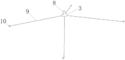
FIG. 1 is a schematic diagram of the overall structure of the present utility model;
FIG. 2 is a schematic view of a circular plate structure according to the present utility model;
FIG. 3 is a schematic structural view of a fixing frame in the present utility model;
fig. 4 is a schematic structural diagram of a slot according to the present utility model.
Wherein: 1. a fixing frame; 2. a collection frame; 3. a circular plate; 4. a slot; 5. a collection net; 6. a rod; 7. a bottom plate; 8. a hook; 9. a connecting rope; 10. and a connecting ring.
Detailed Description
In order that the manner in which the above recited features, objects and advantages of the present utility model are obtained will become readily apparent, a more particular description of the utility model will be rendered by reference to specific embodiments thereof which are illustrated in the appended drawings. Based on the examples in the embodiments, those skilled in the art can obtain other examples without making any inventive effort, which fall within the scope of the utility model. The experimental methods in the following examples are conventional methods unless otherwise specified, and materials, reagents, etc. used in the following examples are commercially available unless otherwise specified.
Examples:
as shown in fig. 1, fig. 2, fig. 3 and fig. 4, a sewage treatment mechanism for a river channel comprises a fixing frame 1, the fixing frame 1 is a rectangular frame, the bottom surface of the fixing frame 1 is fixedly connected with a bottom plate 7, the rear end of the upper surface of the bottom plate 7 is fixedly connected with two inserting rods 6, a collecting mechanism is arranged at the rear of the fixing frame 1, the collecting mechanism comprises a collecting frame 2, a collecting net 5 is fixedly connected to the rear surface of the collecting frame 2, the fixing frame 1 is fixedly arranged on the inner wall of the river channel, the length of the fixing frame 1 can be changed according to the width of the river channel, the length of the bottom plate 7 on the bottom surface of the fixing frame 1 is changed along with the change of the length of the fixing frame 1, no matter how the length of the bottom plate 7 is changed, the two inserting rods 6 are kept at two ends of the bottom plate 7, and in the process of movably sleeving the inserting rods 6 with a slot 4, as the slot diameter of the inserting rods 4 is larger than the rod diameter of the inserting rods 6, the collecting frame 2 can be conveniently clamped with the fixing frame 1, when the inserting rods 6 slide in the slot 4, the collecting frame 2 and the collecting frame 1, the maximum clearance between the collecting frame 2 and the collecting frame 1 is not larger than the net 5, the net 2 and the net 2 is fixedly connected with the collecting ring 10 at the four corners of the collecting frame 2, and the collecting frame is fixedly connected with the collecting frame 10;
the collecting net 5 and the collecting frame 2 can be lifted up and down through the hooks 8, floating dirt in the collecting net 5 is kept in the collecting net 5 and is not easy to fall out of the collecting frame 2, so that the collecting and cleaning of the floating dirt can be operated on the bank of a river channel without entering the river channel, the connecting rings 10 are fixedly connected with the connecting ropes 9, the connecting ropes 9 are fixedly connected with the circular plates 3 at the ends, the hooks 8 are fixedly connected with the upper surface of the circular plates 3, the two ends of the collecting frame 2 are respectively penetrated with the slots 4, the slot diameter of the slots 4 is larger than the rod diameter of the inserting rod 6, and the bottom plate 7 is in movable contact with the bottom surface of the collecting frame 2.
Working principle: when in use, the fixing frame 1 is fixedly arranged on the inner wall of a river channel, the length of the fixing frame 1 can be changed according to the width of the river channel, the length of the bottom plate 7 on the bottom surface of the fixing frame 1 is changed along with the change of the length of the fixing frame 1, no matter how the length of the bottom plate 7 is changed, two inserting rods 6 are kept at two ends of the bottom plate 7, and the inserting rods 6 are movably sleeved with the inserting grooves 4, in the process of movably sleeving the inserting grooves 4, the inserting grooves 4 are larger than the inserting rods 6, so that the collecting frame 2 can be conveniently clamped with the fixing frame 1, and the inserting rods 6 slide in the inserting grooves 4, the maximum gap between the collecting frame 2 and the fixing frame 1 is not larger than the net diameter of the collecting net 5, the collecting net 5 and the collecting frame 2 can be lifted up and down through the hooks 8, so that floating dirt in the collecting net 5 is not easy to fall out from the collecting frame 2 in the lifting process, the floating dirt can be operated on the bank of the river channel, the labor intensity is greatly improved on the basis of reducing the cost, and the labor intensity is reduced.
The embodiments of the present utility model have been described in detail with reference to the drawings, but the present utility model is not limited thereto, and various changes can be made within the knowledge of those skilled in the art without departing from the spirit of the present utility model.
Claims (6)
1. The utility model provides a dirt treatment mechanism for river course, includes mount (1), its characterized in that, mount (1) is rectangular frame, the bottom surface fixedly connected with bottom plate (7) of mount (1), the rear end of bottom plate (7) upper surface is connected with two inserted bars (6), the rear of mount (1) is provided with collection mechanism;
the collecting mechanism comprises a collecting frame (2).
2. The dirt treatment mechanism for the river course according to claim 1, wherein the rear surface of the collecting frame (2) is fixedly connected with a collecting net (5), four corners of the collecting frame (2) are fixedly sleeved with connecting rings (10), and an opening of the collecting net (5) is fixedly connected with the rear edge of the collecting frame (2).
3. The dirt treatment mechanism for the river channel according to claim 2, wherein four connecting rings (10) are fixedly connected with connecting ropes (9), and the end parts of the four connecting ropes (9) are fixedly connected with circular plates (3).
4. A soil treatment mechanism for a river course as claimed in claim 3, wherein the upper surface of the circular plate (3) is fixedly connected with a hook (8).
5. The dirt handling mechanism for river courses according to claim 4, wherein the two ends of the collecting frame (2) are provided with slots (4) in a penetrating mode, and the diameter of each slot (4) is larger than that of each inserting rod (6).
6. The river sewage treatment mechanism according to claim 5, wherein the bottom plate (7) is in movable contact with the bottom surface of the collecting frame (2).
Priority Applications (1)
| Application Number | Priority Date | Filing Date | Title |
|---|---|---|---|
| CN202223438377.4U CN219099985U (en) | 2022-12-20 | 2022-12-20 | Dirt treatment mechanism for river channel |
Applications Claiming Priority (1)
| Application Number | Priority Date | Filing Date | Title |
|---|---|---|---|
| CN202223438377.4U CN219099985U (en) | 2022-12-20 | 2022-12-20 | Dirt treatment mechanism for river channel |
Publications (1)
| Publication Number | Publication Date |
|---|---|
| CN219099985U true CN219099985U (en) | 2023-05-30 |
Family
ID=86457378
Family Applications (1)
| Application Number | Title | Priority Date | Filing Date |
|---|---|---|---|
| CN202223438377.4U Active CN219099985U (en) | 2022-12-20 | 2022-12-20 | Dirt treatment mechanism for river channel |
Country Status (1)
| Country | Link |
|---|---|
| CN (1) | CN219099985U (en) |
-
2022
- 2022-12-20 CN CN202223438377.4U patent/CN219099985U/en active Active
Similar Documents
| Publication | Publication Date | Title |
|---|---|---|
| CN212835824U (en) | Urban planning ground rainwater flood storage seepage device | |
| CN219099985U (en) | Dirt treatment mechanism for river channel | |
| CN208465258U (en) | A kind of coagulation device of waste water suspension | |
| CN210975767U (en) | Rural garbage treatment device | |
| CN212104477U (en) | Rainwater grate convenient to disassemble and assemble | |
| CN215626845U (en) | Artificial grid for sewage treatment | |
| CN219702681U (en) | Benthos gathers back washing separator | |
| CN216586459U (en) | River course refuse treatment device for hydraulic engineering | |
| CN220696081U (en) | Sewage treatment fine grid of high-efficient edulcoration | |
| CN220184132U (en) | Water conservancy construction dredging device | |
| CN214783730U (en) | Hydraulic engineering fishway structure | |
| CN213014605U (en) | Basket type grating and intercepting well | |
| CN219260932U (en) | Automatic dirt blocking and cleaning device for hydropower station | |
| CN219508511U (en) | River course grid trash cleaning device of water conservancy construction | |
| CN219773153U (en) | Rainwater grate for filtering primary rainwater | |
| CN214363715U (en) | River course cleaning device for hydraulic engineering of simple operation | |
| CN214528651U (en) | Sludge water filtering device | |
| CN212091113U (en) | Filter equipment for hydraulic engineering | |
| CN219195893U (en) | River surge maintenance equipment | |
| CN212396021U (en) | Chemical wastewater filtering device | |
| CN220565378U (en) | Municipal works ground rainwater seepage flow device | |
| CN216006893U (en) | A filter equipment for hydraulic and hydroelectric engineering | |
| CN220318729U (en) | Equipment pump house ground drainage dirt intercepting well based on comprehensive utilization of waste water of thermal power plant | |
| CN212575774U (en) | Sewage filter convenient to dismantle and strain basket | |
| CN210887137U (en) | Gate controller |
Legal Events
| Date | Code | Title | Description |
|---|---|---|---|
| GR01 | Patent grant | ||
| GR01 | Patent grant |