CN219093835U - Stainless steel product cutting device with automatic dust removal function - Google Patents
Stainless steel product cutting device with automatic dust removal function Download PDFInfo
- Publication number
- CN219093835U CN219093835U CN202223305705.3U CN202223305705U CN219093835U CN 219093835 U CN219093835 U CN 219093835U CN 202223305705 U CN202223305705 U CN 202223305705U CN 219093835 U CN219093835 U CN 219093835U
- Authority
- CN
- China
- Prior art keywords
- fixed
- stainless steel
- steel product
- base
- cutting device
- Prior art date
- Legal status (The legal status is an assumption and is not a legal conclusion. Google has not performed a legal analysis and makes no representation as to the accuracy of the status listed.)
- Active
Links
Images


Classifications
-
- Y—GENERAL TAGGING OF NEW TECHNOLOGICAL DEVELOPMENTS; GENERAL TAGGING OF CROSS-SECTIONAL TECHNOLOGIES SPANNING OVER SEVERAL SECTIONS OF THE IPC; TECHNICAL SUBJECTS COVERED BY FORMER USPC CROSS-REFERENCE ART COLLECTIONS [XRACs] AND DIGESTS
- Y02—TECHNOLOGIES OR APPLICATIONS FOR MITIGATION OR ADAPTATION AGAINST CLIMATE CHANGE
- Y02P—CLIMATE CHANGE MITIGATION TECHNOLOGIES IN THE PRODUCTION OR PROCESSING OF GOODS
- Y02P70/00—Climate change mitigation technologies in the production process for final industrial or consumer products
- Y02P70/10—Greenhouse gas [GHG] capture, material saving, heat recovery or other energy efficient measures, e.g. motor control, characterised by manufacturing processes, e.g. for rolling metal or metal working
Landscapes
- Sawing (AREA)
Abstract
The utility model relates to the technical field of stainless steel product cutting, in particular to a stainless steel product cutting device with an automatic dust removing function. This stainless steel products cutting device with automatic dust removal function drives the carousel through first motor drive transmission shaft and rotates for the carousel drives the connecting rod and rotates, make the slide then slide in the base and drive the pinion rack and upwards slide, make the pinion rack drive the gear rotation, make the gear drive the clamp lever rotate and drive the connecting rod and rotate, make the clamp lever outwards expand in order that stainless steel products main part centre gripping wherein, start first motor reverse rotation later and make the slide drive the pinion rack and glide, thereby make the gear inwards rotate simultaneously and drive the clamp lever inwards rotate firm to stainless steel products centre gripping, thereby avoid manual support to be influenced safety in utilization by cutter fish tail in the in-process of cutting, the security of improvement use.
Description
Technical Field
The utility model relates to the technical field of stainless steel product cutting, in particular to a stainless steel product cutting device with an automatic dust removing function.
Background
The stainless steel products are made of stainless steel materials and are acid and alkali resistant, so that the grade of SUS304 food sanitation is achieved, and the stainless steel products are stainless steel cabinets, garbage cans and the like, and accord with GMP certification. Because the stainless steel product has the characteristics of smooth and firm surface, difficult dirt accumulation and convenient cleaning, the stainless steel product is widely applied to the fields of building material decoration, food processing, catering, brewing, chemical industry and the like. In the process of producing the stainless steel product, a cutting device is required to cut the stainless steel product.
Most of the existing stainless steel cutting is to place a stainless steel product on a table top, cut the stainless steel product by manually supporting and using a cutting knife, however, the cutting knife is easy to scratch in the manual supporting process, so that the safety coefficient of cutting is reduced, the cutting efficiency is low, dust generated in the cutting process is sucked into a human body by manual cutting, and the human body is damaged.
Disclosure of Invention
The utility model aims to provide a stainless steel product cutting device with an automatic dust removing function, which solves the problems that in the prior art, most of the existing stainless steel cutting is that the stainless steel product is placed on a table top and is cut by a cutting knife through manual support, however, the cutting knife is easily scratched in the manual support process, so that the safety coefficient of cutting is reduced, the cutting efficiency is low, and dust generated in the cutting process is sucked into a human body through manual cutting, so that the human body is damaged. In order to achieve the above purpose, the present utility model provides the following technical solutions: the utility model provides a stainless steel products cutting device with automatic dust removal function, includes the base, the upper end of base has stainless steel products main part through the clamping assembly joint, the top of base is fixed with through lifting assembly and puts the thing board, the lower extreme of putting the thing board is through reciprocal subassembly sliding connection having electric knife, the top of electric knife is fixed with the loop bar, the bottom of loop bar is fixed with the dust catcher.
Preferably, the clamping assembly comprises a base, the inside at the base is fixed to the base, the top of base is fixed with first motor, the output of first motor is fixed with the transmission shaft, the tip of transmission shaft is fixed with the carousel, the surface hinge of carousel has the connecting rod, the other end hinge of connecting rod has the slide, slide and base sliding connection, the top of slide is fixed with the pinion rack, the both ends meshing of pinion rack has the gear, the centre rotation of gear is connected with the back shaft, back shaft and base fixed connection, the tip cover of gear is established and is fixed with the clamp lever, the tip of clamp lever is glued there is the abrasionproof pad, the tip hinge of clamp lever has the connecting rod, the tip hinge of connecting rod has the supporting shoe, supporting shoe and base fixed connection.
Preferably, the clamping rod is clamped with the stainless steel product body, and the stainless steel product body is attached to the wear-resistant pad.
Preferably, the lifting assembly comprises a support column, the support column is fixed at the top of the base, a second motor is fixed in the support column, a screw rod is fixed at the output end of the second motor, a support is connected to the outer wall of the screw rod in a sliding mode, and a storage plate is fixed in the middle of the support.
Preferably, the reciprocating assembly comprises a connecting plate, the connecting plate is fixed in the middle of the support, the top of connecting plate is fixed with the bracing piece, the end fixing of bracing piece has the pivot, the outer wall rotation of pivot is connected with the crank, first logical groove has been seted up to the inside of crank, the inside sliding connection in first logical groove has first lug, the end fixing of first lug has the runner, the middle fixed transmission pole of runner, the end fixing of transmission pole has the third motor.
Preferably, the crank is internally provided with a second through groove, a second lug is connected in a sliding manner in the second through groove, a sliding block is fixed at the end part of the second lug, the sliding block is connected with the storage plate in a sliding manner, and the bottom of the sliding block is fixedly connected with the electric cutter.
Compared with the prior art, the utility model has the beneficial effects that:
according to the utility model, the first motor is used for driving the transmission shaft to drive the turntable to rotate, so that the turntable drives the connecting rod to rotate, the sliding plate at the end part of the connecting rod slides in the base along with the rotation of the connecting rod and drives the toothed plate at the top of the sliding plate to slide upwards, the toothed plate drives the gear to rotate, the gear drives the clamping rod to rotate and drives the connecting rod to rotate, the clamping rod is outwards expanded to be convenient for clamping the stainless steel product main body, then the first motor is started to reversely rotate, the sliding plate drives the toothed plate to slide downwards, the gear simultaneously inwards rotates and drives the clamping rod to inwards rotate, so that the stainless steel product is firmly clamped, the phenomenon that the manual support is scratched by the cutter in the cutting process, the use safety is influenced, and the use safety is improved.
According to the utility model, the first motor is started to drive the transmission shaft to drive the turntable to rotate, so that the turntable drives the connecting rod to rotate, the sliding plate at the end part of the connecting rod slides in the base along with the turntable and drives the toothed plate at the top of the sliding plate to slide upwards, the toothed plate drives the gear to rotate, the gear drives the clamping rod to rotate and drives the connecting rod to rotate, the clamping rod is outwards expanded to be convenient for clamping the stainless steel product main body, then the first motor is started to reversely rotate, the sliding plate drives the toothed plate to slide downwards, the gear simultaneously inwards rotates and drives the clamping rod to inwards rotate, so that the stainless steel product is firmly clamped, the phenomenon that the manual support is scratched by the cutter in the cutting process is avoided, the use safety is influenced, and the use safety is improved.
Drawings
FIG. 1 is a schematic diagram of the overall structure of the present utility model;
FIG. 2 is a schematic view of a clamping assembly according to the present utility model;
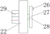
fig. 3 is a schematic diagram of a connection structure between a third motor and a rotating wheel according to the present utility model.
In the figure: 1. a base; 2. a stainless steel article body; 3. a base; 4. a first motor; 5. a transmission shaft; 6. a turntable; 7. a connecting rod; 8. a slide plate; 9. a toothed plate; 10. a gear; 11. a support shaft; 12. a clamping rod; 13. an abrasion-proof pad; 14. a connecting rod; 15. a support block; 16. a support post; 17. a second motor; 18. a screw rod; 19. a bracket; 20. a connecting plate; 21. a storage plate; 22. a support rod; 23. a rotating shaft; 24. a crank; 25. a first through groove; 26. a first bump; 27. a rotating wheel; 28. a transmission rod; 29. a third motor; 30. a second through slot; 31. a second bump; 32. a slide block; 33. an electric cutter; 34. a loop bar; 35. a dust collector.
Detailed Description
The following description of the embodiments of the present utility model will be made clearly and completely with reference to the accompanying drawings, in which it is apparent that the embodiments described are only some embodiments of the present utility model, but not all embodiments. All other embodiments, which are obtained by a worker of ordinary skill in the art without creative efforts, are within the protection scope of the present utility model based on the embodiments of the present utility model.
Referring to fig. 1 to 3, the present utility model provides a technical solution: the utility model provides a stainless steel products cutting device with automatic dust removal function, includes base 1, and the upper end of base 1 has stainless steel products main part 2 through the clamping assembly joint, and the top of base 1 is fixed with puts thing board 21 through the lifting assembly, and the lower extreme of putting thing board 21 is through reciprocal subassembly sliding connection having electric knife 33, and electric knife 33's top is fixed with loop bar 34, and the bottom of loop bar 34 is fixed with dust catcher 35.
In this embodiment, as shown in fig. 1, fig. 2 and fig. 3, the clamping assembly includes a base 3, the base 3 is fixed in the inside of base 1, the top of base 1 is fixed with first motor 4, the output of first motor 4 is fixed with transmission shaft 5, the tip of transmission shaft 5 is fixed with carousel 6, the surface of carousel 6 articulates there is connecting rod 7, the other end of connecting rod 7 articulates there is slide 8, slide 8 and base 3 sliding connection, the top of slide 8 is fixed with pinion rack 9, the both ends meshing of pinion 9 has gear 10, the centre rotation of gear 10 is connected with back shaft 11, back shaft 11 and base 1 fixed connection, the tip cover of gear 10 is established and is fixed with clamp lever 12, the tip of clamp lever 12 is glued and is stamped 13, the tip of clamp lever 12 articulates there is connecting rod 14, the tip of connecting rod 14 articulates there is supporting shoe 15, supporting shoe 15 and base 1 fixed connection, start first motor 4 drive transmission shaft 5 drive carousel 6 rotate, make the slide 8 of connecting rod 7 drive the top slide, slide 9 follow-up in base 3 slides and drives the pinion 9 at 8 top, the pinion 9 makes gear 10 to drive up, make the pinion 10 drive the pinion 10 and drive the gear 10 and make the clamp lever 10 and drive the clamp lever 10 and rotate, thereby the clamp lever 12 and make the clamp lever 12 to rotate, the inside the cut out of the product is difficult to be rotated, and the clamp is made to be held by the clamp and is safe to the clamp in order to rotate, the clamp the inside the product is easy to be rotated, the clamp to be cut and is easy to the inside the clamp to be rotated, the inside the clamp in the safety, the clamp is used to the clamp to the inside the handle to the cutter is rotated and is rotated to the inside a cutter to be rotated and is rotated to the inside a cutter to and is rotated and to a cutter to and is a cutter to and a cutter handle to and a cutter handle is used to and a cutter to is made.
In this embodiment, as shown in fig. 1, 2 and 3, the clamping rod 12 is clamped with the stainless steel product body, the stainless steel product body is attached to the anti-wear pad 13, and the anti-wear pad 13 prevents the clamping rod 12 from pressing when clamping the stainless steel product body 2.
In this embodiment, as shown in fig. 1, 2 and 3, the lifting assembly includes a support column 16, the support column 16 is fixed at the top of the base 1, a second motor 17 is fixed in the support column 16, a screw rod 18 is fixed at the output end of the second motor 17, a support 19 is slidably connected to the outer wall of the screw rod 18, a storage plate 21 is fixed in the middle of the support 19, the second motor 17 is started to drive the screw rod 18 to rotate, so that the support 19 slides along with lifting, thereby adjusting the cutting distance between the electric cutter 33 and the stainless steel product, and the electric cutter 33 is attached to the surface of the stainless steel product.
In this embodiment, as shown in fig. 1, 2 and 3, the reciprocating assembly includes a connecting plate 20, the connecting plate 20 is fixed in the middle of the support 19, a supporting rod 22 is fixed at the top of the connecting plate 20, a rotating shaft 23 is fixed at the end of the supporting rod 22, a crank 24 is rotatably connected to the outer wall of the rotating shaft 23, a first through groove 25 is opened in the crank 24, a first bump 26 is slidably connected in the first through groove 25, a rotating wheel 27 is fixed at the end of the first bump 26, a transmission rod 28 is fixed in the middle of the rotating wheel 27, a third motor 29 is fixed at the end of the transmission rod 28, the third motor 29 is started to drive the transmission rod 28 to drive the rotating wheel 27 to rotate, the first bump 26 on the surface of the rotating wheel 27 slides in the first through groove 25 in the crank 24, the outer wall of the outer rotating shaft 23 of the crank 24 swings, the second bump 31 on the surface of the slider 32 slides in the second through groove 30 in the surface of the crank 24 when the cutter 24 swings, the slider 32 slides reciprocally in the storage plate 21, the electric 33 at the bottom of the slider 32 slides reciprocally, so as to cut the stainless steel main body 2, the working efficiency is improved, and dust is prevented from being absorbed by dust in the end of the cutter 35 during the installation process.
In this embodiment, as shown in fig. 1, 2 and 3, a second through slot 30 is provided in the crank 24, a second bump 31 is slidably connected in the second through slot 30, a slider 32 is fixed at an end of the second bump 31, the slider 32 is slidably connected with the object placing plate 21, a bottom of the slider 32 is fixedly connected with the electric cutter 33, and the electric cutter 33 is driven to slide back and forth by the slider 32.
The application method and the advantages of the utility model are as follows: when the stainless steel product cutting device with the automatic dust removing function works, the working process is as follows:
as shown in fig. 1, 2 and 3, when the cutting device is used for cutting a stainless steel product, the stainless steel product is firstly clamped, the first motor 4 is started to drive the transmission shaft 5 to drive the turntable 6 to rotate, the turntable 6 drives the connecting rod 7 to rotate, the sliding plate 8 at the end part of the connecting rod 7 slides in the base 3 and drives the toothed plate 9 at the top of the sliding plate 8 to slide upwards, the toothed plate 9 drives the gear 10 to rotate, the gear 10 drives the clamping rod 12 to rotate and drives the connecting rod 7 to rotate, the clamping rod 12 expands outwards to facilitate the clamping of the stainless steel product main body 2 therein, then the first motor 4 is started to rotate reversely, the sliding plate 8 drives the toothed plate 9 to slide downwards, the gear 10 simultaneously rotates inwards and drives the clamping rod 12 to rotate inwards to firmly clamp the stainless steel product, the use safety is prevented from being influenced by the scratch of a cutter in the process of manually holding the cutting, the use safety is improved, the second motor 17 is started to drive the screw rod 18 to rotate, the bracket 19 is driven to slide along with the screw rod, so that the cutting distance between the electric cutter 33 and a stainless steel product is adjusted, the electric cutter 33 is attached to the surface of the stainless steel product, the third motor 29 is started to drive the transmission rod 28 to drive the rotating wheel 27 to rotate, the first lug 26 on the surface of the rotating wheel 27 slides along with the first through groove 25 in the crank 24, the outer wall of the outer rotating shaft 23 is stressed by the crank 24 to swing, the second lug 31 on the surface of the sliding block 32 slides along with the second through groove 30 on the surface of the crank 24 during driving to swing, the sliding block 32 is stressed to slide back and forth in the object placing plate 21, the electric cutter 33 at the bottom of the sliding block 32 slides back and forth, so that the stainless steel product main body 2 is cut, and the work efficiency is improved, and in the cutting process, dust generated in the cutting process is adsorbed by the dust collector 35 arranged at the end part, so that dust is prevented from drifting, and the processing environment is prevented from being influenced.
The foregoing has shown and described the basic principles, principal features and advantages of the utility model. It will be understood by those skilled in the art that the present utility model is not limited to the above-described embodiments, and that the above-described embodiments and descriptions are only preferred embodiments of the present utility model, and are not intended to limit the utility model, and that various changes and modifications may be made therein without departing from the spirit and scope of the utility model as claimed. The scope of the utility model is defined by the appended claims and equivalents thereof.
Claims (6)
1. Stainless steel product cutting device with automatic dust removal function, including base (1), its characterized in that: the stainless steel product is characterized in that the stainless steel product main body (2) is clamped at the upper end of the base (1) through a clamping assembly, the object placing plate (21) is fixed at the top of the base (1) through a lifting assembly, an electric cutter (33) is connected at the lower end of the object placing plate (21) through a reciprocating assembly in a sliding mode, a sleeve rod (34) is fixed at the top of the electric cutter (33), and a dust collector (35) is fixed at the bottom of the sleeve rod (34).
2. The stainless steel product cutting device with an automatic dust removing function according to claim 1, wherein: the clamping assembly comprises a base (3), the inside at base (1) is fixed to base (3), the top of base (1) is fixed with first motor (4), the output of first motor (4) is fixed with transmission shaft (5), the end fixing of transmission shaft (5) has carousel (6), the surface hinge of carousel (6) has connecting rod (7), the other end hinge of connecting rod (7) has slide (8), slide (8) and base (3) sliding connection, the top of slide (8) is fixed with pinion rack (9), the both ends meshing of pinion rack (9) has gear (10), the intermediate rotation of gear (10) is connected with back shaft (11), back shaft (11) and base (1) fixed connection, the tip cover of gear (10) is fixed with clamp lever (12), the tip of clamp lever (12) has glued wear pad (13), the tip hinge of clamp lever (12) has connecting rod (14), the tip of connecting rod (14) has supporting shoe (15) and fixed connection base (15).
3. The stainless steel product cutting device with an automatic dust removing function according to claim 2, wherein: the clamping rod (12) is clamped with the stainless steel product body, and the stainless steel product body is attached to the anti-abrasion pad (13).
4. The stainless steel product cutting device with an automatic dust removing function according to claim 1, wherein: the lifting assembly comprises a support column (16), the support column (16) is fixed at the top of the base (1), a second motor (17) is fixed in the support column (16), a screw rod (18) is fixed at the output end of the second motor (17), a support frame (19) is connected to the outer wall of the screw rod (18) in a sliding mode, and a storage plate (21) is fixed in the middle of the support frame (19).
5. The stainless steel product cutting device with an automatic dust removing function according to claim 1, wherein: the reciprocating assembly comprises a connecting plate (20), the connecting plate (20) is fixed in the middle of a support (19), a supporting rod (22) is fixed at the top of the connecting plate (20), a rotating shaft (23) is fixed at the end part of the supporting rod (22), a crank (24) is rotatably connected to the outer wall of the rotating shaft (23), a first through groove (25) is formed in the crank (24), a first lug (26) is connected to the first through groove (25) in a sliding mode, a rotating wheel (27) is fixed at the end part of the first lug (26), a transmission rod (28) is fixed in the middle of the rotating wheel (27), and a third motor (29) is fixed at the end part of the transmission rod (28).
6. The stainless steel product cutting device with an automatic dust removing function according to claim 5, wherein: the inside of crank (24) has seted up second through groove (30), the inside sliding connection of second through groove (30) has second lug (31), the tip of second lug (31) is fixed with slider (32), slider (32) and thing board (21) sliding connection, the bottom and the electric cutter (33) fixed connection of slider (32).
Priority Applications (1)
| Application Number | Priority Date | Filing Date | Title |
|---|---|---|---|
| CN202223305705.3U CN219093835U (en) | 2022-12-08 | 2022-12-08 | Stainless steel product cutting device with automatic dust removal function |
Applications Claiming Priority (1)
| Application Number | Priority Date | Filing Date | Title |
|---|---|---|---|
| CN202223305705.3U CN219093835U (en) | 2022-12-08 | 2022-12-08 | Stainless steel product cutting device with automatic dust removal function |
Publications (1)
| Publication Number | Publication Date |
|---|---|
| CN219093835U true CN219093835U (en) | 2023-05-30 |
Family
ID=86453236
Family Applications (1)
| Application Number | Title | Priority Date | Filing Date |
|---|---|---|---|
| CN202223305705.3U Active CN219093835U (en) | 2022-12-08 | 2022-12-08 | Stainless steel product cutting device with automatic dust removal function |
Country Status (1)
| Country | Link |
|---|---|
| CN (1) | CN219093835U (en) |
-
2022
- 2022-12-08 CN CN202223305705.3U patent/CN219093835U/en active Active
Similar Documents
| Publication | Publication Date | Title |
|---|---|---|
| CN211241640U (en) | Apple deep-processing is with device of peeling | |
| CN219093835U (en) | Stainless steel product cutting device with automatic dust removal function | |
| CN209478363U (en) | A kind of furniture factory lumber plate cutting machine | |
| CN213797116U (en) | Trimming device for wooden furniture | |
| CN112157735B (en) | Kitchen red iron wood round chopping board cutting device | |
| CN212096621U (en) | Tailoring machine equipment for clothing production | |
| CN214185546U (en) | Sheet metal cutting and clamping device | |
| CN210500638U (en) | Wood board chamfering machine | |
| CN214925215U (en) | Environment-friendly wood cutting device for furniture processing | |
| CN216328893U (en) | Timber processingequipment who cuts edge fast | |
| CN220547704U (en) | Cutting pump cutting mechanism capable of preventing winding | |
| CN220073395U (en) | Automatic change equipment of tailorring | |
| CN219632715U (en) | Cutting machine | |
| CN217756326U (en) | Draw-off rope can | |
| CN220806810U (en) | Polishing device for production of kitchen ware, bamboo and wood products | |
| CN219027817U (en) | Comb tooth machine convenient to location | |
| CN220897885U (en) | Hami melon peeler | |
| CN215700429U (en) | Quick deburring device based on plastic products | |
| CN218429247U (en) | Aerated concrete building block brick production is with slotting device from dust type | |
| CN216729888U (en) | Stainless steel pot forming edge trimmer | |
| CN218838360U (en) | Plastic products processing is with compressing tightly positioner | |
| CN220840618U (en) | Adjustable chamfer cutting device | |
| CN219380896U (en) | Saw cutting device convenient for pet house processing | |
| CN218984903U (en) | Paper cutter convenient to fixed paper | |
| CN220806826U (en) | Stainless steel knife fork burnishing device |
Legal Events
| Date | Code | Title | Description |
|---|---|---|---|
| GR01 | Patent grant | ||
| GR01 | Patent grant |