CN212096621U - A kind of cutting machine equipment for garment production - Google Patents
A kind of cutting machine equipment for garment production Download PDFInfo
- Publication number
- CN212096621U CN212096621U CN202020342066.XU CN202020342066U CN212096621U CN 212096621 U CN212096621 U CN 212096621U CN 202020342066 U CN202020342066 U CN 202020342066U CN 212096621 U CN212096621 U CN 212096621U
- Authority
- CN
- China
- Prior art keywords
- frame
- bottom end
- screw
- work table
- face
- Prior art date
- Legal status (The legal status is an assumption and is not a legal conclusion. Google has not performed a legal analysis and makes no representation as to the accuracy of the status listed.)
- Expired - Fee Related
Links
- 238000004519 manufacturing process Methods 0.000 title claims abstract description 19
- 238000005520 cutting process Methods 0.000 title claims description 23
- 239000012535 impurity Substances 0.000 claims abstract description 23
- 230000007246 mechanism Effects 0.000 claims abstract description 21
- 238000004140 cleaning Methods 0.000 claims description 19
- VYPSYNLAJGMNEJ-UHFFFAOYSA-N Silicium dioxide Chemical compound O=[Si]=O VYPSYNLAJGMNEJ-UHFFFAOYSA-N 0.000 claims description 6
- 239000000741 silica gel Substances 0.000 claims description 6
- 229910002027 silica gel Inorganic materials 0.000 claims description 6
- 239000011111 cardboard Substances 0.000 claims description 4
- 238000000034 method Methods 0.000 abstract description 15
- 230000008569 process Effects 0.000 abstract description 12
- 230000009286 beneficial effect Effects 0.000 abstract description 4
- 230000000694 effects Effects 0.000 abstract description 2
- 230000005012 migration Effects 0.000 abstract 1
- 238000013508 migration Methods 0.000 abstract 1
- 230000009471 action Effects 0.000 description 5
- 239000004744 fabric Substances 0.000 description 5
- 239000000463 material Substances 0.000 description 5
- 230000008901 benefit Effects 0.000 description 4
- 230000006872 improvement Effects 0.000 description 4
- 238000005304 joining Methods 0.000 description 3
- 229910000975 Carbon steel Inorganic materials 0.000 description 2
- 239000010962 carbon steel Substances 0.000 description 2
- 238000007796 conventional method Methods 0.000 description 1
- 230000007812 deficiency Effects 0.000 description 1
- 238000010586 diagram Methods 0.000 description 1
- 239000000428 dust Substances 0.000 description 1
- 238000012986 modification Methods 0.000 description 1
- 230000004048 modification Effects 0.000 description 1
- 238000011144 upstream manufacturing Methods 0.000 description 1
- 238000003466 welding Methods 0.000 description 1
Images



Landscapes
- Apparatuses For Bulk Treatment Of Fruits And Vegetables And Apparatuses For Preparing Feeds (AREA)
Abstract
Description
技术领域technical field
本实用新型涉及剪裁机相关领域,具体是一种服装生产用剪裁机设备。The utility model relates to the related field of cutting machines, in particular to a cutting machine equipment for garment production.
背景技术Background technique
目前,随着人类社会的进步,各行各业都得到充足的发展,尤其是制衣行业,在近几年内有着日新月异的变化,服装业是我国制造业中具有较高竞争力和较好发展势头的行业,己经逐渐成为新时期的经济增长点,服装业的发展不仅可以带动上、下游相关产业的发展,而且服装业的发展还可以解决我国大量人口的就业,服装剪裁机可以方便工作人员剪裁布料,是服装厂必不可少的设备。At present, with the progress of human society, all walks of life have been fully developed, especially the garment industry, which has undergone rapid changes in recent years. The industry has gradually become an economic growth point in the new era. The development of the clothing industry can not only drive the development of upstream and downstream related industries, but also solve the employment of a large number of people in my country, and the clothing cutting machine can facilitate the staff. Cutting fabrics is an essential equipment for garment factories.
当布料在剪裁完成后,剪裁过程中产生的碎屑会残留在剪裁台上,同时剪裁台长时间放置暴露在外面容易积累上杂质,从而影响到下一次的剪裁工作,而常用的解决方式为人工进行清理,当碎屑较多时,碎屑难以进行快速完全的收集,为工作带来不便。When the fabric is cut, the debris generated during the cutting process will remain on the cutting table. At the same time, if the cutting table is exposed to the outside for a long time, it is easy to accumulate impurities, which will affect the next cutting work. The common solution is: Manual cleaning, when there are many debris, it is difficult to collect the debris quickly and completely, which brings inconvenience to the work.
实用新型内容Utility model content
因此,为了解决上述不足,本实用新型在此提供一种服装生产用剪裁机设备。Therefore, in order to solve the above deficiencies, the present invention provides a tailoring machine for garment production.
本实用新型是这样实现的,构造一种服装生产用剪裁机设备,该装置包括丝杆、工作桌和收集机构,所述丝杆设置有两个分别位于工作桌内部后端和机架内侧顶端,且两个丝杆侧表面分别与机架右端面后下端和剪裁器前端面顶部开设的螺孔内侧螺纹连接,所述工作桌左端面后上端和后端面中下部分别安装有第一电机和控制器,所述第一电机右侧输出轴穿过工作桌左端面后固定连接于后侧的丝杆左端面,所述机架滑动安装于工作桌外侧顶端,且机架前端面顶部锁合有第二电机,所述第二电机后端输出轴穿过机架前端面后固定连接于前侧的丝杆前端面,所述剪裁器滑动安装于机架内侧顶端,所述第一电机和第二电机与控制器进行电连接,所述收集机构设置于工作桌右侧,所述收集机构由衔接槽、衔接框、收集框、除杂机构、中空箱、固定板、套筒、转杆、卡板、套环和弹簧组成,所述衔接槽开设于工作桌顶部右端,所述衔接框锁合于工作桌右端面顶部,所述收集框活动伸入于衔接框外侧底端,所述除杂机构设置于机架内侧顶端,所述中空箱紧固于衔接框前后两端底部,所述固定板为一体化结构设置于收集框前后两端顶部,所述套筒紧固于固定板底端面,所述转杆穿过套筒和固定板底端面后固定连接于卡板底端面前端,所述卡板贯穿于中空箱底端面开设的方孔内侧,所述套环活动嵌套于转杆外侧中部,且套环侧表面贴合于套筒内圈,所述弹簧两端分别固定连接于套环底端面和套筒内侧底端面。The utility model is realized by constructing a cutting machine equipment for garment production. The device comprises a screw rod, a work table and a collecting mechanism. , and the side surfaces of the two screw rods are respectively threaded with the rear lower end of the right end face of the frame and the inner side of the screw holes opened at the top of the front end face of the cutter, and the upper rear end of the left end face of the work table and the middle lower part of the rear end face are respectively installed with the first motor and The controller, the right output shaft of the first motor passes through the left end face of the work table and is fixedly connected to the left end face of the screw rod on the rear side, the frame is slidably installed on the outer top of the work table, and the top of the front end face of the frame is locked There is a second motor, the rear end output shaft of the second motor passes through the front end face of the frame and is fixedly connected to the front end face of the lead screw on the front side, the trimmer is slidably installed on the inner top end of the frame, the first motor and The second motor is electrically connected to the controller, the collecting mechanism is arranged on the right side of the work table, and the collecting mechanism is composed of a connecting groove, a connecting frame, a collecting frame, an impurity removing mechanism, a hollow box, a fixing plate, a sleeve, and a rotating rod , a clamping plate, a collar and a spring, the connecting groove is opened on the right end of the top of the work table, the connecting frame is locked on the top of the right end surface of the working table, the collecting frame is movably extended into the bottom end of the outside of the connecting frame, and the The impurity removal mechanism is arranged at the top of the inner side of the frame, the hollow box is fastened to the bottom of the front and rear ends of the connecting frame, the fixing plate is an integrated structure and is arranged on the top of the front and rear ends of the collecting frame, and the sleeve is fastened to the fixing plate The bottom end face, the rotating rod passes through the sleeve and the bottom end face of the fixed plate and is fixedly connected to the front end of the bottom end face of the clamping plate, the clamping plate penetrates the inner side of the square hole opened on the bottom end face of the hollow box, and the collar is movably nested in the rotating shaft. The middle part of the outer side of the rod, the side surface of the collar is attached to the inner ring of the sleeve, and the two ends of the spring are respectively fixedly connected to the bottom end surface of the collar and the inner bottom end surface of the sleeve.
优选的,所述除杂机构由转盘、螺杆、除杂刷、固定筒和滑杆组成,所述转盘底端面中部紧固有螺杆,所述螺杆侧表面与机架顶端面左端中部开设的螺孔内侧螺纹连接,且螺杆外侧底端与除杂刷顶端面中部转动连接,所述固定筒锁合于机架内侧顶端面左端,所述滑杆紧固于除杂刷顶端面后端,且滑杆活动伸入于固定筒内侧。Preferably, the impurity removal mechanism is composed of a turntable, a screw rod, an impurity removal brush, a fixed cylinder and a sliding rod, a screw rod is fastened in the middle of the bottom end face of the turntable, and a screw rod opened in the middle part of the left end of the top surface of the frame and the side surface of the screw rod The inner side of the hole is threadedly connected, and the outer bottom end of the screw rod is rotatably connected with the middle part of the top surface of the cleaning brush, the fixing cylinder is locked on the left end of the inner top surface of the frame, and the sliding rod is fastened to the rear end of the top surface of the cleaning brush, and The sliding rod movably extends into the inner side of the fixed cylinder.
优选的,所述衔接框呈由上而下渐缩的锥形状,且衔接框的左端面顶部开设有相对应于衔接槽的开口。Preferably, the connecting frame is tapered from top to bottom, and the top of the left end face of the connecting frame is provided with an opening corresponding to the connecting groove.
优选的,所述衔接槽的内侧底端面和工作桌顶端面呈45°夹角,且衔接槽的内侧底端面设置有一层光滑薄膜层。Preferably, the inner bottom end surface of the connecting groove and the top surface of the working table form an included angle of 45°, and a smooth film layer is provided on the inner bottom end surface of the connecting groove.
优选的,所述转杆的外侧底端设置有防滑纹,且防滑纹呈垂直延伸状。Preferably, the outer bottom end of the rotating rod is provided with an anti-skid pattern, and the anti-skid pattern extends vertically.
优选的,所述收集框为方形状,且收集框的内侧长度为25cm。Preferably, the collection frame is in a square shape, and the inner length of the collection frame is 25 cm.
优选的,所述卡板的底端面粘贴有一层柔性硅胶层,且硅胶层的厚度为0.2cm。Preferably, a layer of flexible silica gel layer is pasted on the bottom end surface of the card board, and the thickness of the silica gel layer is 0.2 cm.
优选的,所述滑杆对称设置有两个于除杂刷顶部前后两端,且工作桌内侧顶端相对应设置有两个滑杆。Preferably, two sliding bars are symmetrically arranged at the front and rear ends of the top of the cleaning brush, and two sliding bars are correspondingly arranged at the top of the inner side of the work table.
优选的,所述弹簧材质为碳钢材质。Preferably, the material of the spring is carbon steel.
优选的,所述收集框材质为PP塑料材质。Preferably, the material of the collection frame is PP plastic material.
本实用新型具有如下优点:本实用新型通过改进在此提供一种服装生产用剪裁机设备,与同类型设备相比,具有如下改进:The utility model has the following advantages: the utility model provides a kind of tailoring machine equipment for garment production through improvement, and compared with the same type of equipment, the utility model has the following improvements:
优点一:本实用新型所述一种服装生产用剪裁机设备,本实用新型通过设置了收集机构在工作桌的顶部,通过转动转盘带动螺杆转动,而螺杆在转动过程带动除杂刷向下移动接触到工作桌的顶端面,此时启动第一电机,使得第一电机的输出轴带动后端的丝杆转动,而机架在后端丝杆的作用下向右水平移动,从而实现除杂刷在向右移动的过程将工作桌顶部的碎屑和杂质向右推动,并且通过衔接槽进入到衔接框内,最后通过衔接框进入到收集框内进行收集,达到了快速将剪裁台上的碎屑和杂质进行清理,为工作带来方便的有益效果。Advantage 1: The utility model is a kind of cutting machine equipment for clothing production. The utility model sets the collection mechanism on the top of the work table, and drives the screw to rotate by rotating the turntable, and the screw drives the cleaning brush to move downward during the rotation process. When it touches the top surface of the work table, the first motor is activated at this time, so that the output shaft of the first motor drives the screw rod at the rear end to rotate, and the frame moves horizontally to the right under the action of the screw rod at the rear end, so as to realize the cleaning brush. In the process of moving to the right, the debris and impurities on the top of the work table are pushed to the right, and enter the connecting frame through the connecting groove, and finally enter the collecting frame through the connecting frame for collection, so as to quickly remove the debris on the cutting table. Dust and impurities are cleaned up, bringing convenient and beneficial effects to the work.
优点二:本实用新型所述一种服装生产用剪裁机设备,本实用新型通过转杆的外侧底端设置有防滑纹,且防滑纹呈垂直延伸状,达到了防止在转动转杆的过程中滑动的有益效果。Advantage 2: The utility model is a kind of cutting machine equipment for clothing production. The utility model is provided with anti-skid lines on the outer bottom end of the rotating rod, and the anti-skid lines extend vertically, which can prevent the rotation of the rotating rod. The beneficial effect of sliding.
附图说明Description of drawings
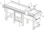
图1是本实用新型结构示意图;Fig. 1 is the structural representation of the present utility model;
图2是本实用新型的收集机构结构示意图;Fig. 2 is the structural representation of the collection mechanism of the present utility model;
图3是本实用新型收集框连接结构示意图;3 is a schematic diagram of the connection structure of the collecting frame of the present invention;
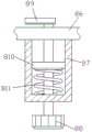
图4是本实用新型的套筒正视剖面结构示意图;4 is a schematic view of the front cross-sectional structure of the sleeve of the present invention;
图5是本实用新型除杂机构右视剖面结构示意图。FIG. 5 is a schematic view of the cross-sectional structure of the impurity removing mechanism of the present invention, as viewed from the right side.
其中:丝杆-1、工作桌-2、控制器-3、第一电机-4、机架-5、第二电机-6、剪裁器-7、收集机构-8、衔接槽-81、衔接框-82、收集框-83、除杂机构-84、中空箱-85、固定板-86、套筒-87、转杆-88、卡板-89、套环-810、弹簧-811、转盘-841、螺杆-842、除杂刷-843、固定筒-844、滑杆-845。Among them: screw-1, work table-2, controller-3, first motor-4, frame-5, second motor-6, cutter-7, collecting mechanism-8, connecting groove-81, connecting Frame-82, Collection frame-83, Impurity removal mechanism-84, Hollow box-85, Fixed plate-86, Sleeve-87, Rod-88, Card plate-89, Sleeve-810, Spring-811, Turntable -841, screw-842, cleaning brush-843, fixed cylinder-844, sliding bar-845.
具体实施方式Detailed ways
下面将结合附图1-5对本实用新型进行详细说明,对本实用新型实施例中的技术方案进行清楚、完整地描述,显然,所描述的实施例仅仅是本实用新型一部分实施例,而不是全部的实施例。基于本实用新型中的实施例,本领域普通技术人员在没有做出创造性劳动前提下所获得的所有其他实施例,都属于本实用新型保护的范围。The present utility model will be described in detail below with reference to the accompanying drawings 1-5, and the technical solutions in the embodiments of the present utility model will be described clearly and completely. Obviously, the described embodiments are only some of the embodiments of the present utility model, not all of them. example. Based on the embodiments of the present invention, all other embodiments obtained by those of ordinary skill in the art without creative work fall within the protection scope of the present invention.
本实用新型通过改进在此提供一种服装生产用剪裁机设备,包括丝杆1、工作桌2和收集机构8,丝杆1设置有两个分别位于工作桌2内部后端和机架5内侧顶端,且两个丝杆1侧表面分别与机架5右端面后下端和剪裁器7前端面顶部开设的螺孔内侧螺纹连接,工作桌2左端面后上端和后端面中下部分别安装有第一电机4和控制器3,第一电机4右侧输出轴穿过工作桌2左端面后固定连接于后侧的丝杆1左端面,机架5滑动安装于工作桌2外侧顶端,且机架5前端面顶部锁合有第二电机6,第二电机6后端输出轴穿过机架5前端面后固定连接于前侧的丝杆1前端面,剪裁器7滑动安装于机架5内侧顶端,第一电机4和第二电机6与控制器3进行电连接,收集机构8设置于工作桌2右侧,收集机构8由衔接槽81、衔接框82、收集框83、除杂机构84、中空箱85、固定板86、套筒87、转杆88、卡板89、套环810和弹簧811组成,衔接槽81开设于工作桌2顶部右端,衔接框82锁合于工作桌2右端面顶部,便于将碎屑和杂质进行输送,收集框83活动伸入于衔接框82外侧底端,除杂机构84设置于机架5内侧顶端,中空箱85紧固于衔接框82前后两端底部,固定板86为一体化结构设置于收集框83前后两端顶部,套筒87紧固于固定板86底端面,转杆88穿过套筒87和固定板86底端面后固定连接于卡板89底端面前端,卡板89贯穿于中空箱85底端面开设的方孔内侧,便于对收集框83的位置进行固定,套环810活动嵌套于转杆88外侧中部,且套环810侧表面贴合于套筒87内圈,弹簧811两端分别固定连接于套环810底端面和套筒87内侧底端面,便于转杆88快速复位。The utility model is improved to provide a tailoring machine for garment production, which includes a screw rod 1, a work table 2 and a
进一步的,所述除杂机构84由转盘841、螺杆842、除杂刷843、固定筒844和滑杆845组成,所述转盘841底端面中部紧固有螺杆842,所述螺杆842侧表面与机架5顶端面左端中部开设的螺孔内侧螺纹连接,且螺杆842外侧底端与除杂刷843顶端面中部转动连接,便于带动除杂刷843进行垂直移动,所述固定筒844锁合于机架5内侧顶端面左端,所述滑杆845紧固于除杂刷843顶端面后端,且滑杆845活动伸入于固定筒844内侧,使得除杂刷843垂直移动过程更加稳定。Further, the
进一步的,所述衔接框82呈由上而下渐缩的锥形状,且衔接框82的左端面顶部开设有相对应于衔接槽81的开口,便于快速将碎屑导入到衔接框82内。Further, the
进一步的,所述衔接槽81的内侧底端面和工作桌2顶端面呈45°夹角,且衔接槽81的内侧底端面设置有一层光滑薄膜层,使得碎屑快速在衔接槽81内滑动。Further, the inner bottom end surface of the connecting
进一步的,所述转杆88的外侧底端设置有防滑纹,且防滑纹呈垂直延伸状,防止在转动的过程中滑动。Further, the outer bottom end of the rotating
进一步的,所述收集框83为方形状,且收集框83的内侧长度为25cm,使得手机的碎屑量更多。Further, the
进一步的,所述卡板89的底端面粘贴有一层柔性硅胶层,且硅胶层的厚度为0.2cm,使得卡板89在放置过程更加稳定。Further, a layer of flexible silica gel layer is pasted on the bottom surface of the
进一步的,所述滑杆845对称设置有两个于除杂刷843顶部前后两端,且工作桌2内侧顶端相对应设置有两个滑杆845,使得除杂刷843的移动过程更加稳定。Further, two sliding
进一步的,所述弹簧811材质为碳钢材质,硬度较大,不易损坏。Further, the material of the
进一步的,所述收集框83材质为PP塑料材质,材质较轻,并且携带。Further, the
本实用新型通过改进提供一种服装生产用剪裁机设备,其工作原理如下;The utility model provides a kind of cutting machine equipment for garment production through improvement, and its working principle is as follows;
第一,首先将该装置整体放置在指定的位置上,并且将需要进行剪裁的布料放置在工作桌2顶端面的指定位置上,然后通过控制器3启动第一电机4和第二电机6,使得第一电机4和第二电机6的输出轴分别带动两个与之固定连接的丝杆1进行转动,而机架5在后侧丝杆1的作用下进行水平左右移动,而剪裁器7在前端丝杆1的作用下进行水平前后移动,从而实现对剪裁器7进行前后左右移动而对布料进行剪裁;First, first place the device as a whole in a designated position, and place the fabric to be cut on the designated position on the top surface of the work table 2, and then start the first motor 4 and the second motor 6 through the controller 3, The output shafts of the first motor 4 and the second motor 6 respectively drive the two screw rods 1 that are fixedly connected with them to rotate, and the
第二,当剪裁结束后可将第二电机6进行断电,并且将布料取下,而需要对工作桌2顶端面的碎屑进行收集处理时,可通过转动转盘841带动螺杆842转动,而螺杆842在转动过程带动除杂刷843向下移动接触到工作桌2的顶端面,此时启动第一电机4,使得第一电机4的输出轴带动后端的丝杆1转动,而机架5在后端的丝杆1的作用下向右水平移动,从而实现除杂刷843在向右移动的过程将工作桌2顶部的碎屑和杂质向右推动,并且通过衔接槽81进入到衔接框82内,最后通过衔接框82进入到收集框83内进行收集;Second, when the cutting is completed, the second motor 6 can be powered off and the cloth can be removed, and when the debris on the top surface of the work table 2 needs to be collected and processed, the
第三,最后可通过转动转杆88带动卡板89进行转动,而在卡板89在转动90°移动相平行于中空箱85底部的方形孔,此时转杆88受到弹簧811的弹力向下移动,然后向下拉动收集框83,并且对收集框83内的碎屑和杂质进行进一步处理。Third, finally, the clamping
本实用新型通过改进提供一种服装生产用剪裁机设备,通过转动转盘841带动螺杆842转动,而螺杆842在转动过程带动除杂刷843向下移动接触到工作桌2的顶端面,此时启动第一电机4,使得第一电机4的输出轴带动后端的丝杆1转动,而机架5在后端的丝杆1的作用下向右水平移动,从而实现除杂刷843在向右移动的过程将工作桌2顶部的碎屑和杂质向右推动,并且通过衔接槽81进入到衔接框82内,最后通过衔接框82进入到收集框83内进行收集,达到了快速将剪裁台上的碎屑和杂质进行清理,为工作带来方便的有益效果,通过转杆88的外侧底端设置有防滑纹,且防滑纹呈垂直延伸状,达到了防止在转动转杆88的过程中滑动的有益效果。The utility model provides a kind of cutting machine equipment for garment production through improvement. By rotating the
以上显示和描述了本实用新型的基本原理和主要特征和本实用新型的优点,并且本实用新型使用到的标准零件均可以从市场上购买,异形件根据说明书的和附图的记载均可以进行订制,各个零件的具体连接方式均采用现有技术中成熟的螺栓铆钉、焊接等常规手段,机械、零件和设备均采用现有技术中,常规的型号,加上电路连接采用现有技术中常规的连接方式,在此不再详述。The basic principle and main features of the present invention and the advantages of the present invention are shown and described above, and the standard parts used in the present invention can be purchased from the market, and the special-shaped parts can be made according to the description in the description and the drawings. Customized, the specific connection method of each part adopts the conventional methods such as mature bolts, rivets and welding in the existing technology, and the machinery, parts and equipment adopt the conventional models in the existing technology, and the circuit connection adopts the existing technology. The conventional connection method will not be described in detail here.
对所公开的实施例的上述说明,使本领域专业技术人员能够实现或使用本实用新型。对这些实施例的多种修改对本领域的专业技术人员来说将是显而易见的,本文中所定义的一般原理可以在不脱离本实用新型的精神或范围的情况下,在其它实施例中实现。因此,本实用新型将不会被限制于本文所示的这些实施例,而是要符合与本文所公开的原理和新颖特点相一致的最宽的范围。The above description of the disclosed embodiments enables those skilled in the art to implement or use the present invention. Various modifications to these embodiments will be readily apparent to those skilled in the art, and the generic principles defined herein may be implemented in other embodiments without departing from the spirit or scope of the present invention. Thus, the present invention is not intended to be limited to the embodiments shown herein, but is to be accorded the widest scope consistent with the principles and novel features disclosed herein.
Claims (8)
Priority Applications (1)
| Application Number | Priority Date | Filing Date | Title |
|---|---|---|---|
| CN202020342066.XU CN212096621U (en) | 2020-03-18 | 2020-03-18 | A kind of cutting machine equipment for garment production |
Applications Claiming Priority (1)
| Application Number | Priority Date | Filing Date | Title |
|---|---|---|---|
| CN202020342066.XU CN212096621U (en) | 2020-03-18 | 2020-03-18 | A kind of cutting machine equipment for garment production |
Publications (1)
| Publication Number | Publication Date |
|---|---|
| CN212096621U true CN212096621U (en) | 2020-12-08 |
Family
ID=73633610
Family Applications (1)
| Application Number | Title | Priority Date | Filing Date |
|---|---|---|---|
| CN202020342066.XU Expired - Fee Related CN212096621U (en) | 2020-03-18 | 2020-03-18 | A kind of cutting machine equipment for garment production |
Country Status (1)
| Country | Link |
|---|---|
| CN (1) | CN212096621U (en) |
Cited By (1)
| Publication number | Priority date | Publication date | Assignee | Title |
|---|---|---|---|---|
| CN115247368A (en) * | 2021-12-16 | 2022-10-28 | 浙江理工大学 | A cutting device for garment proofing |
-
2020
- 2020-03-18 CN CN202020342066.XU patent/CN212096621U/en not_active Expired - Fee Related
Cited By (2)
| Publication number | Priority date | Publication date | Assignee | Title |
|---|---|---|---|---|
| CN115247368A (en) * | 2021-12-16 | 2022-10-28 | 浙江理工大学 | A cutting device for garment proofing |
| CN115247368B (en) * | 2021-12-16 | 2024-06-07 | 浙江理工大学 | Tailoring device for garment proofing |
Similar Documents
| Publication | Publication Date | Title |
|---|---|---|
| CN210657337U (en) | Novel quick-witted two-sided dust removal of weaving device | |
| CN206319182U (en) | A kind of clothing expands cutter with cloth | |
| CN218558128U (en) | Biodegradable plastic bag notching machine | |
| CN221480368U (en) | Collection subassembly of embroidery surface fabric cutting equipment | |
| CN207859613U (en) | A kind of waste material recovery device of pod making machine | |
| CN109930374A (en) | A kind of Environmental-protecting dust-removing weaving cloth cropping cutting high-efficient automatic all-in-one machine | |
| CN213295896U (en) | Production equipment for textile fabric clothes | |
| CN211092068U (en) | Garment processing device with cleaning function | |
| CN213677526U (en) | Medical isolation suit cloth compaction device | |
| CN209903136U (en) | High-efficient clear spinning workbench | |
| CN210965983U (en) | Operation panel for tailoring | |
| CN210747472U (en) | Garment processing device with cleaning function | |
| CN220554406U (en) | Vamp burr trimming structure | |
| CN217710054U (en) | Textile garment cutting device | |
| CN211645756U (en) | Cutting machine for clothing production | |
| CN219886422U (en) | Clothing cutter with automatic feeding function | |
| CN222477080U (en) | Tailoring equipment convenient for collecting waste materials for clothing production | |
| CN216274941U (en) | A cutting equipment for garment production | |
| CN214561234U (en) | Multifunctional cutting knife for textile chemical industry | |
| CN214061183U (en) | A plastic runway drawing machine | |
| CN211620970U (en) | Tailoring equipment in clothing production process | |
| CN221640421U (en) | Plastic product edging device | |
| CN222205839U (en) | A textile clothing cutting device | |
| CN224173097U (en) | A cutting device for textile and apparel processing | |
| CN222135304U (en) | A bamboo ring outer wall slotting device |
Legal Events
| Date | Code | Title | Description |
|---|---|---|---|
| GR01 | Patent grant | ||
| GR01 | Patent grant | ||
| CF01 | Termination of patent right due to non-payment of annual fee | ||
| CF01 | Termination of patent right due to non-payment of annual fee |
Granted publication date: 20201208 |