CN219074477U - Clamp for milling screw holes and peripheral molded surfaces of supporting piece - Google Patents
Clamp for milling screw holes and peripheral molded surfaces of supporting piece Download PDFInfo
- Publication number
- CN219074477U CN219074477U CN202223149087.8U CN202223149087U CN219074477U CN 219074477 U CN219074477 U CN 219074477U CN 202223149087 U CN202223149087 U CN 202223149087U CN 219074477 U CN219074477 U CN 219074477U
- Authority
- CN
- China
- Prior art keywords
- base body
- milling
- screw holes
- support
- clamp
- Prior art date
- Legal status (The legal status is an assumption and is not a legal conclusion. Google has not performed a legal analysis and makes no representation as to the accuracy of the status listed.)
- Active
Links
Images


Classifications
-
- Y—GENERAL TAGGING OF NEW TECHNOLOGICAL DEVELOPMENTS; GENERAL TAGGING OF CROSS-SECTIONAL TECHNOLOGIES SPANNING OVER SEVERAL SECTIONS OF THE IPC; TECHNICAL SUBJECTS COVERED BY FORMER USPC CROSS-REFERENCE ART COLLECTIONS [XRACs] AND DIGESTS
- Y02—TECHNOLOGIES OR APPLICATIONS FOR MITIGATION OR ADAPTATION AGAINST CLIMATE CHANGE
- Y02P—CLIMATE CHANGE MITIGATION TECHNOLOGIES IN THE PRODUCTION OR PROCESSING OF GOODS
- Y02P70/00—Climate change mitigation technologies in the production process for final industrial or consumer products
- Y02P70/10—Greenhouse gas [GHG] capture, material saving, heat recovery or other energy efficient measures, e.g. motor control, characterised by manufacturing processes, e.g. for rolling metal or metal working
Abstract
The utility model discloses a clamp for milling screw holes and peripheral molded surfaces of a supporting piece, which comprises a base body, wherein the supporting piece is fixed on the base body, and two support arms of the supporting piece, which are to be drilled with the screw holes, extend out of the base body; one end of the base body is fixed on a chuck of the machine tool, and the other end is tightly propped by a workbench of the machine tool. The clamp has the advantages of simple structure and short manufacturing period. The numerical control machine tool accessory and the machine tool function are matched, the application effect is good, and the machining efficiency is high.
Description
Technical Field
The utility model belongs to the technical field of machining, and particularly relates to a clamp for milling screw holes and peripheral molded surfaces of a supporting piece.
Background
A cross-shaped supporting piece is characterized in that four support arms are symmetrical in pairs, screw holes are formed in one pair of downwardly inclined support arms, and the other pair of support arms are of a straight structure. The periphery of the screw hole is provided with special profiles which are parallel or perpendicular to the axis of the screw hole. The traditional scheme is to design a machining jig and a milling machine fixture, which are used for solving the technical problems of machining screw holes and special profiles around, and the machining jig and the milling machine fixture which are required to be designed at least comprise a foundation base, positioning, clamping, indexing and the like, have a complex structure, and are required to be carried out in four steps. The fixture has the problems of complex structure, long fixture manufacturing period, low efficiency, difficulty in meeting the production progress requirement and the like.
Disclosure of Invention
Object of the Invention
In order to solve the problems, the utility model provides a fixture for milling screw holes and peripheral molded surfaces of a supporting piece.
Technical solution of the utility model
A clamp for milling screw holes and peripheral molded surfaces of support pieces comprises a base body, wherein the support pieces are fixed on the base body, and two support arms of the support pieces, which are to be drilled with the screw holes, extend out of the base body; one end of the base body is fixed on a chuck of the machine tool, and the other end is tightly propped by a workbench of the machine tool.
Preferably, the base body is provided with a recess for receiving the support member.
Preferably, the hexagonal structure at one end of the base body is used for clamping a chuck of a machine tool, and the end face of the other end, which is tightly propped by a workbench of the machine tool, is provided with a center hole.
Preferably, the two straight support arms of the support piece are fixed on the base body through the cylindrical positioning bolts and the diamond positioning bolts respectively, and the support piece is pressed on the base body through nuts.
Preferably, the ends of the cylindrical positioning bolts and the diamond positioning bolts are fastened by anti-rotation screws.
Preferably, a reference hole is formed in the base body at the intersection point of the opposite surface of the groove for accommodating the support piece, corresponding to the axis of the base body, and the axes of the two support arms of the screw hole to be drilled of the support piece, and the reference hole is used as a numerical control milling origin O (0.0.0).
Preferably, the substrate is formed by forging or sheet metal processing.
Preferably, the blank of the substrate is subjected to magnetic flaw detection.
Preferably, the base body is provided with a plurality of weight-reducing grooves.
The utility model has the advantages that: the clamp has the advantages of simple structure and short manufacturing period. The numerical control machine tool accessory and the machine tool function are matched, the application effect is good, and the machining efficiency is high.
Drawings
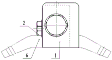
Fig. 1 is a schematic structural view of a fixture for milling screw holes and peripheral profiles of a support member according to the present utility model.
Fig. 2 is a cross-sectional view A-A of fig. 1.
Fig. 3 is a B-B cross-sectional view of fig. 1.
Fig. 4 is a top view of fig. 1.
Fig. 5 is a right side view of fig. 4.
Fig. 6 is a bottom view of fig. 4.
Fig. 7 is a state diagram of a screw hole processing process.
Fig. 8 is a perspective view of the No. 6 piece support.
Fig. 9 is a perspective view of a fixture of the present utility model milling support screw holes and peripheral profiles.
In the figure, a 1-base body, a 2-nut, a 3-diamond positioning bolt, a 4-screw, a 5-cylindrical positioning bolt and a 6-support.
Detailed Description
The utility model is realized by the following technical scheme.
The utility model provides a milling support screw and peripheral profile's anchor clamps, includes base member 1, is equipped with the groove that can hold support member 6 middle part and a pair of support arm straight on the base member 1, and outside two support arms that need bore the screw stretched out base member 1, base member 1 one end was the hexagonal that can be pressed from both sides tightly by the lathe chuck, and the other end terminal surface was equipped with the centre bore that supplies the lathe workstation to prop up tightly. The straight pair of support arms are fixed on the base body 1 through a cylindrical positioning bolt 5, a diamond positioning bolt 3 and a nut 2 respectively, and are fastened through an anti-rotation screw 4. On the surface of the base body 1 opposite to the groove accommodating the support 6, a reference hole is opened at the intersection point of the axis of the base body 1 and the axes of the pair of arms to be drilled as a numerical control milling origin O (0.0.0). The base body 1 is manufactured by forging or sheet metal processing, and defects are detected through magnetic flaw detection. Several lightening grooves are also formed on the base body 1, and the effect is to lighten the whole weight of the clamp.
The processing process is as follows: the condition before the working procedure of the supporting piece 6 meets the requirement is ensured, the supporting piece 6 is installed on the base body 1, two support arms of a screw hole to be processed of the supporting piece 6 extend towards the direction far away from the base body 1, a cylindrical positioning bolt 5 and a diamond positioning bolt 3 are adopted to fix the two straight support arms, a nut 2 is connected to the cylindrical positioning bolt 5 and the diamond positioning bolt 3 to tightly press the supporting piece 6, a machine tool chuck clamps a hexagonal body of the base body 1, and a machine tool workbench tightly presses a center hole on the base body 1. The tool is used for locating a machining original point O (0.0.0), the workbench is rotated to the position where the support piece 6 needs to be drilled with screw holes, and after the screw holes are machined, the tool is replaced, and the peripheral molded surface of the screw holes is machined. And adjusting the numerical control program to the position of the other screw hole, and processing the screw hole. And replacing the cutter in the same way, and processing the peripheral molded surface of the screw hole.
The above embodiments are only for illustrating the technical concept and features of the present utility model, and are intended to enable those skilled in the art to understand the content of the present utility model and implement it accordingly, and are not intended to limit the scope of the present utility model, but all equivalent changes or modifications made according to the spirit of the present utility model should be included in the scope of the present utility model. The technology, shape, and construction parts of the present utility model, which are not described in detail, are known in the art.
Claims (9)
1. The clamp for milling the screw holes and the peripheral molded surfaces of the supporting pieces is characterized by comprising a base body (1), wherein the supporting pieces (6) are fixed on the base body (1), and two support arms of the supporting pieces (6) for drilling the screw holes extend out of the base body (1); one end of the base body (1) is fixed on a chuck of a machine tool, and the other end is tightly propped by a workbench of the machine tool.
2. A clamp for milling support screw holes and peripheral profiles according to claim 1, characterized in that the basic body (1) is provided with grooves for receiving the support (6).
3. A fixture for milling screw holes and peripheral profiles of support members according to claim 1, characterized in that the hexagonal structure at one end of the basic body (1) is clamped by a chuck of a machine tool, and the other end face of the basic body, which is held against by a table of the machine tool, is provided with a centre hole.
4. A clamp for milling a screw hole and a peripheral profile of a support member according to claim 1, characterized in that the two straight arms of the support member (6) are fixed to the base body (1) by means of a cylindrical positioning bolt (5) and a diamond-shaped positioning bolt (3), respectively, and the support member (6) is pressed against the base body (1) by means of a nut (2).
5. A clamp for milling support screw holes and peripheral profiles according to claim 4, characterized in that the ends of the cylindrical positioning bolts (5) and the diamond-shaped positioning bolts (3) are fastened by means of anti-rotation screws (4).
6. A fixture for milling a screw hole and a peripheral profile of a support member according to claim 2, wherein a reference hole is formed in the base body (1) at the intersection point of the opposite surface of the groove for accommodating the support member (6) corresponding to the axis of the base body (1) and the axes of two arms of the screw hole to be drilled of the support member (6), as a numerical control milling origin O (0.0.0).
7. A fixture for milling screw holes and peripheral profiles of support members according to any of claims 1-6, characterized in that the base body (1) is machined from forging or sheet metal.
8. A clamp for milling support screw holes and peripheral profiles according to claim 7, characterized in that the blank of the basic body (1) is subjected to a magnetic flaw detection.
9. A clamp for milling support screw holes and peripheral profiles according to claim 7, characterized in that the basic body (1) is provided with a number of weight-reducing grooves.
Priority Applications (1)
| Application Number | Priority Date | Filing Date | Title |
|---|---|---|---|
| CN202223149087.8U CN219074477U (en) | 2022-11-25 | 2022-11-25 | Clamp for milling screw holes and peripheral molded surfaces of supporting piece |
Applications Claiming Priority (1)
| Application Number | Priority Date | Filing Date | Title |
|---|---|---|---|
| CN202223149087.8U CN219074477U (en) | 2022-11-25 | 2022-11-25 | Clamp for milling screw holes and peripheral molded surfaces of supporting piece |
Publications (1)
| Publication Number | Publication Date |
|---|---|
| CN219074477U true CN219074477U (en) | 2023-05-26 |
Family
ID=86399860
Family Applications (1)
| Application Number | Title | Priority Date | Filing Date |
|---|---|---|---|
| CN202223149087.8U Active CN219074477U (en) | 2022-11-25 | 2022-11-25 | Clamp for milling screw holes and peripheral molded surfaces of supporting piece |
Country Status (1)
| Country | Link |
|---|---|
| CN (1) | CN219074477U (en) |
-
2022
- 2022-11-25 CN CN202223149087.8U patent/CN219074477U/en active Active
Similar Documents
| Publication | Publication Date | Title |
|---|---|---|
| CN214135038U (en) | Four-axis rotary fixture | |
| CN112388362B (en) | Fixture combination for machining rotary pipe joint with ball by numerical control lathe and machining method | |
| CN103042408B (en) | End plane turning universal fixture for special-shaped parts | |
| CN219074477U (en) | Clamp for milling screw holes and peripheral molded surfaces of supporting piece | |
| CN111168425A (en) | Clamp for machining inclined plane of small end of connecting rod | |
| CN113579750B (en) | Speed reducer semi-camshaft accompanying tool | |
| CN213053760U (en) | Fixing clamp for processing shaft workpieces | |
| CN214488973U (en) | Frock clamp that mould processing milling machine was used | |
| CN112809432A (en) | Milling machine fixture | |
| CN113732757A (en) | Clamp for processing machine tool cushion block and processing method thereof | |
| CN215659050U (en) | Dovetail groove type clamp | |
| CN220561007U (en) | Frock of tilting table | |
| CN220259633U (en) | Valve core overturning type drill jig | |
| CN112823984A (en) | Fixture for drilling L-shaped part and using method | |
| CN111283316A (en) | Electron beam welding universal platform | |
| CN220718473U (en) | Clamp for processing square adjusting nut | |
| CN220260225U (en) | Drilling and milling special fixture | |
| CN217551813U (en) | Crossbeam frock | |
| CN220636985U (en) | Clamp applicable to machine tools with various shapes | |
| CN217292024U (en) | Mounting fixture for machining | |
| CN213470376U (en) | Reference plane machining clamp for geometric body with irregular shape | |
| CN213970802U (en) | Standard angle pushes up fast machining anchor clamps to one side | |
| CN217991720U (en) | Fixture tool for shaft | |
| CN219684693U (en) | Clamping tool for multi-angle machining of hydraulic cylinder earrings | |
| CN216029364U (en) | Processing clamping tool |
Legal Events
| Date | Code | Title | Description |
|---|---|---|---|
| GR01 | Patent grant | ||
| GR01 | Patent grant |