CN219060306U - Municipal drainage pipeline dredging device - Google Patents
Municipal drainage pipeline dredging device Download PDFInfo
- Publication number
- CN219060306U CN219060306U CN202223248081.6U CN202223248081U CN219060306U CN 219060306 U CN219060306 U CN 219060306U CN 202223248081 U CN202223248081 U CN 202223248081U CN 219060306 U CN219060306 U CN 219060306U
- Authority
- CN
- China
- Prior art keywords
- dredging
- pipe
- filter screen
- auger
- box body
- Prior art date
- Legal status (The legal status is an assumption and is not a legal conclusion. Google has not performed a legal analysis and makes no representation as to the accuracy of the status listed.)
- Active
Links
Images


Abstract
The utility model belongs to the technical field of pipeline dredging, in particular to a municipal drainage pipeline dredging device, which comprises a bottom plate and a dredging pipeline arranged at the top of the bottom plate, wherein the top of the dredging pipeline is communicated with a filtering box body, an arc-shaped filter screen is arranged in the filtering box body, a first auger is arranged in the filtering box body and positioned on the top surface of the arc-shaped filter screen, one side of the filtering box body is communicated with a slag discharging pipe, the first auger extends to the inner side of the slag discharging pipe, a second auger is arranged in the dredging pipeline, a motor is arranged at one end of the top of the bottom plate, and an output shaft of the motor is fixedly connected with one end of the second auger through a coupler.
Description
Technical Field
The utility model belongs to the technical field of pipeline dredging, and particularly relates to a municipal drainage pipeline dredging device.
Background
After the existing municipal drainage pipeline is used for a long time, sludge is accumulated in the municipal drainage pipeline, and the drainage efficiency is affected; particularly, when the filter screen is used for a long time, a plurality of impurities can be accumulated on the surface of the filter screen, so that the filter device is easy to block, the impurities can be always accumulated, the drainage pipeline is blocked, the drainage effect is influenced, silt is easy to deposit and form silt through the filter screen, and the drainage efficiency of the pipeline is influenced.
Therefore, a municipal drainage pipeline dredging device is designed to solve the problems.
Disclosure of Invention
To solve the problems set forth in the background art. The utility model provides a municipal drainage pipeline dredging device which can be used for rapidly cleaning sludge at a filter screen, and meanwhile, sundries on the filter screen can be conveniently cleaned, the drainage pipeline is prevented from being blocked, and the drainage effect and efficiency are improved.
In order to achieve the above purpose, the present utility model provides the following technical solutions: the utility model provides a municipal drainage pipe dredging device, includes the bottom plate and installs dredging pipe at bottom plate top, dredging pipe's top intercommunication has the rose box body, the internally mounted of rose box body has the arc filter screen, the inside of rose box body just is located the top surface of arc filter screen and installs first auger, one side intercommunication of rose box body has the scum pipe, just first auger extends to the scum pipe inboard, dredging pipe's internally mounted has the second auger, the motor is installed to bottom plate's top one end, the output shaft of motor passes through the one end fixed connection of shaft coupling and second auger, just pass through belt pulley and belt on the output shaft of motor and be connected with the one end transmission of first auger.
Preferably, the top of dredging pipe is linked together there is adapter sleeve, adapter sleeve's top is through flange sealing connection there being the drainage return bend, just adapter sleeve's inboard is connected with platy filter screen.
Preferably, the top of the inner side of the connecting sleeve is provided with a mounting groove, and the edge of the plate-shaped filter screen is connected to the inner side of the mounting groove in a sliding manner.
Preferably, one end of the dredging pipeline, which is close to the motor, is of a sealed structure, the other end of the dredging pipeline is of an open structure, and a dredging valve is arranged at the position, which is close to the opening of the dredging pipeline.
Preferably, the bottom of the filtering box body is funnel-shaped, the top of the filtering box body is communicated with a water inlet pipe, and a slag discharging valve is arranged at the outlet of the slag discharging pipe.
Preferably, the bottom surface of the arc-shaped filter screen is uniformly connected with a reinforcing lath.
Compared with the prior art, the utility model has the beneficial effects that:
1. the arc-shaped filter screen is arranged in the filter box body, so that sewage in the drain pipe can be filtered, sundries are collected, meanwhile, sediment can be deposited in the dredging pipeline, the motor drives the first auger and the second auger to rotate together, sundries in the arc-shaped filter screen can be cleaned, meanwhile, the sludge in the dredging pipeline is cleaned, the drain pipeline is prevented from being blocked, and the drain effect and efficiency are improved;
2. through the drainage return bend in desilting pipeline top department, the water drainage after the filtration of being convenient for to combine and be equipped with platy filter screen in adapter sleeve, can filter once more, guaranteed the unobstructed of drainage, conveniently pull down the drainage return bend, be convenient for clear up the washing to platy filter screen, facilitate the use.
Drawings
The accompanying drawings are included to provide a further understanding of the utility model and are incorporated in and constitute a part of this specification, illustrate the utility model and together with the embodiments of the utility model, serve to explain the utility model. In the drawings:
FIG. 1 is a schematic view of the overall exterior of the present utility model;
FIG. 2 is a schematic view of the overall internal structure of the present utility model;
FIG. 3 is a schematic view of the structure of one end of the inside of the filtering box according to the present utility model;
FIG. 4 is a schematic view of the structure of the connecting sleeve and the plate filter screen in the present utility model;
in the figure:
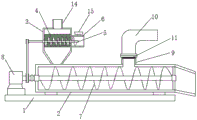
1. a bottom plate; 2. dredging pipelines; 3. a filter box; 4. an arc-shaped filter screen; 5. a first auger; 6. a slag discharge pipe; 7. a second auger; 8. a motor; 9. a connection sleeve; 10. a drain trap; 11. a plate-shaped filter screen; 12. a mounting groove; 13. a silt removing valve; 14. a water inlet pipe; 15. a slag discharging valve; 16. the slats are reinforced.
Detailed Description
The following description of the embodiments of the present utility model will be made clearly and completely with reference to the accompanying drawings, in which it is apparent that the embodiments described are only some embodiments of the present utility model, but not all embodiments. All other embodiments, which can be made by those skilled in the art based on the embodiments of the utility model without making any inventive effort, are intended to be within the scope of the utility model.
As shown in fig. 1-4;
the utility model provides a municipal drainage pipe dredging device, including bottom plate 1 and the dredging pipe 2 of installing at the bottom plate 1 top, dredging pipe 2's top intercommunication has filter tank 3, filter tank 3's internally mounted has arc filter screen 4, first auger 5 is installed to filter tank 3's inside and the top surface that is located arc filter screen 4, one side intercommunication of filter tank 3 has scum pipe 6, and first auger 5 extends to scum pipe 6 inboard, dredging pipe 2's internally mounted has second auger 7, motor 8 is installed to bottom plate 1's top one end, motor 8's output shaft passes through the one end fixed connection of shaft coupling and second auger 7, and motor 8's output shaft is last to be connected with first auger 5's one end transmission through belt pulley and belt.
In this embodiment: the utility model discloses a municipal drainage pipe based on current takes place the problem that silt blockked up easily in filter screen department, is equipped with arc filter screen 4 in the inside of filtering box 3, can filter the sewage in the drain pipe to collect debris, silt simultaneously can deposit in dredging pipe 2, drive first auger 5 and second auger 7 through motor 8 and rotate together, can clear up arc filter screen 4 debris, clear up silt in dredging pipe 2 simultaneously, prevent to take place that drainage pipe from taking place to block up, improved drainage effect and efficiency.
It should be noted that: the supporting seats are connected to the two sides of the top of the bottom plate 1, and the two ends of the dredging pipeline 2 are fixedly placed on the supporting seats, so that the stability of the dredging pipeline 2 is guaranteed.
In combination with the above, further, the top intercommunication of dredging pipeline 2 has adapter sleeve 9, and flange seal connection has drainage return bend 10 on the top of adapter sleeve 9, and the inboard of adapter sleeve 9 is connected with platy filter screen 11, through the drainage return bend 10 in dredging pipeline 2 top department, the water drainage after being convenient for filter to combine and be equipped with platy filter screen 11 in adapter sleeve 9, can filter once more, guaranteed the unobstructed of drainage, conveniently pull down drainage return bend 10, be convenient for clear up the washing to platy filter screen 11, facilitate the use.
It should be noted that: the mounting groove 12 has been seted up at the inboard top of adapter sleeve 9, and the edge sliding connection of platy filter screen 11 is in the inboard of mounting groove 12, conveniently removes drainage return bend 10, is convenient for take out platy filter screen 11 and carries out the clearance and wash, facilitates the use.
Still further, the one end that dredging pipe 2 is close to motor 8 is established to sealed structure, and the other end is established to open structure, and dredging pipe 2 is close to its open department and install row's silt valve 13, and the one end that motor 8 was kept away from to second auger 7 is rotated through the bearing bracket and is connected in dredging pipe 2 open inboard for motor 8 drives second auger 7 and stably rotates in dredging pipe 2, can discharge silt in the dredging pipe 2 effectively.
Still further, the bottom of filtering box 3 is the funnel form, filtering box 3's top intercommunication has inlet tube 14, slag discharging valve 15 is installed to the exit of scum pipe 6, the bottom surface evenly connected with of arc filter screen 4 consolidates lath 16, in the sewage row of being convenient for the drain pipe goes into filtering box 3 through inlet tube 14, and filter through arc filter screen 4, rotate through first auger 5, can pass through slag discharging valve 15 with filterable debris and discharge, through the reinforcement lath 16 of setting, can increase the supporting strength of arc filter screen 4, prevent that first auger 5 from rotating and causing arc filter screen 4 to warp, the structure is reliable.
Working principle: when using, the position that produces silt easily at municipal drainage pipe will the device inlet tube 14 with drainage pipe's intercommunication, in the sewage row's of drain pipe goes into filtering box 3, can filter the sewage in the drain pipe through arc filter screen 4, and collect debris, then silt can deposit in dredging pipeline 2, the rivers are filtered once more through the platy filter screen 11 in the adapter sleeve 9, then drain through drainage return bend 10, guaranteed the unobstructed of drainage, when the debris of collecting and deposited silt are more, close drainage pipe, then start motor 8 drives first auger 5 and second auger 7 and rotate together, can clear up the debris of arc filter screen 4, clear up the silt in dredging pipeline 2 simultaneously, prevent that drainage pipe from taking place to block up, drainage effect and efficiency have been improved.
Finally, it should be noted that: the foregoing description is only a preferred embodiment of the present utility model, and the present utility model is not limited thereto, but it is to be understood that modifications and equivalents of some of the technical features described in the foregoing embodiments may be made by those skilled in the art, although the present utility model has been described in detail with reference to the foregoing embodiments. Any modification, equivalent replacement, improvement, etc. made within the spirit and principle of the present utility model should be included in the protection scope of the present utility model.
Claims (6)
1. Municipal drainage pipe dredging device, its characterized in that: including bottom plate (1) and install dredging pipe (2) at bottom plate (1) top, dredging pipe (2)'s top intercommunication has rose box body (3), the internally mounted of rose box body (3) has arc filter screen (4), first auger (5) are installed to the inside of rose box body (3) and the top surface that is located arc filter screen (4), one side intercommunication of rose box body (3) has scum pipe (6), just first auger (5) extend to scum pipe (6) inboard, dredging pipe (2) internally mounted has second auger (7), motor (8) are installed to bottom plate (1)'s top one end, the output shaft of motor (8) passes through the one end fixed connection of shaft coupling with second auger (7), just on the output shaft of motor (8) through belt pulley and belt and the one end transmission of first auger (5) is connected.
2. A municipal drainage pipe dredging device according to claim 1, wherein: the top of dredging pipeline (2) is communicated with coupling sleeve (9), the top of coupling sleeve (9) is connected with drain elbow (10) through flange seal, and the inboard of coupling sleeve (9) is connected with platy filter screen (11).
3. A municipal drainage pipe dredging device according to claim 2, wherein: the top of the inner side of the connecting sleeve (9) is provided with a mounting groove (12), and the edge of the plate-shaped filter screen (11) is connected to the inner side of the mounting groove (12) in a sliding manner.
4. A municipal drainage pipe dredging device according to claim 3, wherein: one end of the dredging pipeline (2) close to the motor (8) is of a sealed structure, the other end of the dredging pipeline is of an open structure, and a dredging valve (13) is arranged at the position of the dredging pipeline (2) close to the opening of the dredging pipeline.
5. A municipal drainage pipe dredging device according to claim 1, wherein: the bottom of the filtering box body (3) is funnel-shaped, the top of the filtering box body (3) is communicated with a water inlet pipe (14), and a slag discharging valve (15) is arranged at the outlet of the slag discharging pipe (6).
6. A municipal drainage pipe dredging device according to claim 1, wherein: the bottom surface of the arc-shaped filter screen (4) is uniformly connected with a reinforcing lath (16).
Priority Applications (1)
| Application Number | Priority Date | Filing Date | Title |
|---|---|---|---|
| CN202223248081.6U CN219060306U (en) | 2022-12-06 | 2022-12-06 | Municipal drainage pipeline dredging device |
Applications Claiming Priority (1)
| Application Number | Priority Date | Filing Date | Title |
|---|---|---|---|
| CN202223248081.6U CN219060306U (en) | 2022-12-06 | 2022-12-06 | Municipal drainage pipeline dredging device |
Publications (1)
| Publication Number | Publication Date |
|---|---|
| CN219060306U true CN219060306U (en) | 2023-05-23 |
Family
ID=86376057
Family Applications (1)
| Application Number | Title | Priority Date | Filing Date |
|---|---|---|---|
| CN202223248081.6U Active CN219060306U (en) | 2022-12-06 | 2022-12-06 | Municipal drainage pipeline dredging device |
Country Status (1)
| Country | Link |
|---|---|
| CN (1) | CN219060306U (en) |
-
2022
- 2022-12-06 CN CN202223248081.6U patent/CN219060306U/en active Active
Similar Documents
| Publication | Publication Date | Title |
|---|---|---|
| CN219848484U (en) | Sediment collector | |
| CN219060306U (en) | Municipal drainage pipeline dredging device | |
| CN110981019A (en) | Community sewage discharge device based on sewage treatment | |
| CN212866270U (en) | Be used for district afforestation to irrigate and use rainwater cistern | |
| CN213014573U (en) | Stifled desilting system is prevented to town road engineering | |
| CN212001543U (en) | Based on prefabricated for pump station blowdown circulation system of integration | |
| CN111188241B (en) | A drainage structures for town road | |
| CN216428490U (en) | A pipeline filter equipment for municipal construction drainage | |
| CN216537346U (en) | Water supply and drainage control device for building | |
| CN216142157U (en) | Be used for municipal drainage pipeline to prevent blockking up cleaning device | |
| CN217854877U (en) | Automatic back-flushing net core dirt remover | |
| CN218166138U (en) | Desilting device for urban drainage system | |
| CN217909233U (en) | Power plant domestic sewage treatment device | |
| CN219363452U (en) | Environment-friendly equipment for wastewater treatment | |
| CN218562539U (en) | Sewage blocking device for water channel mouth | |
| CN218011515U (en) | Desilting mechanism for sewage treatment | |
| CN216062220U (en) | Drainage device for municipal works | |
| CN218204806U (en) | Sewage treatment plant is with sewage pipes of automatic mediation | |
| CN219922163U (en) | Slag discharging device of secondary sedimentation tank | |
| CN219502081U (en) | Industrial wastewater filter for environmental protection | |
| CN219343456U (en) | Municipal building drainage economizer | |
| CN220768325U (en) | Drainage well | |
| CN220888912U (en) | Wisdom vatch basin | |
| CN217759184U (en) | Municipal administration public works are with preventing stifled drainage pipe | |
| CN219080536U (en) | Discharge cleaning device convenient to sewer line |
Legal Events
| Date | Code | Title | Description |
|---|---|---|---|
| GR01 | Patent grant | ||
| GR01 | Patent grant |