CN219026894U - Precise polishing tool for driven shaft - Google Patents
Precise polishing tool for driven shaft Download PDFInfo
- Publication number
- CN219026894U CN219026894U CN202223129687.8U CN202223129687U CN219026894U CN 219026894 U CN219026894 U CN 219026894U CN 202223129687 U CN202223129687 U CN 202223129687U CN 219026894 U CN219026894 U CN 219026894U
- Authority
- CN
- China
- Prior art keywords
- fixedly connected
- driven shaft
- wall
- brush main
- support frame
- Prior art date
- Legal status (The legal status is an assumption and is not a legal conclusion. Google has not performed a legal analysis and makes no representation as to the accuracy of the status listed.)
- Active
Links
- 238000005498 polishing Methods 0.000 title claims abstract description 31
- 238000009434 installation Methods 0.000 claims abstract description 18
- 230000002457 bidirectional effect Effects 0.000 claims description 7
- 230000007246 mechanism Effects 0.000 claims description 7
- 244000309464 bull Species 0.000 claims description 5
- 239000012535 impurity Substances 0.000 abstract description 11
- 230000009471 action Effects 0.000 abstract description 7
- 230000000694 effects Effects 0.000 description 4
- XLYOFNOQVPJJNP-UHFFFAOYSA-N water Substances O XLYOFNOQVPJJNP-UHFFFAOYSA-N 0.000 description 4
- 230000005540 biological transmission Effects 0.000 description 3
- 238000012986 modification Methods 0.000 description 2
- 230000004048 modification Effects 0.000 description 2
- 238000007517 polishing process Methods 0.000 description 2
- 238000005452 bending Methods 0.000 description 1
- 230000006835 compression Effects 0.000 description 1
- 238000007906 compression Methods 0.000 description 1
- 238000010586 diagram Methods 0.000 description 1
- 239000002184 metal Substances 0.000 description 1
- 238000000034 method Methods 0.000 description 1
- 230000008569 process Effects 0.000 description 1
Images


Classifications
-
- Y—GENERAL TAGGING OF NEW TECHNOLOGICAL DEVELOPMENTS; GENERAL TAGGING OF CROSS-SECTIONAL TECHNOLOGIES SPANNING OVER SEVERAL SECTIONS OF THE IPC; TECHNICAL SUBJECTS COVERED BY FORMER USPC CROSS-REFERENCE ART COLLECTIONS [XRACs] AND DIGESTS
- Y02—TECHNOLOGIES OR APPLICATIONS FOR MITIGATION OR ADAPTATION AGAINST CLIMATE CHANGE
- Y02P—CLIMATE CHANGE MITIGATION TECHNOLOGIES IN THE PRODUCTION OR PROCESSING OF GOODS
- Y02P70/00—Climate change mitigation technologies in the production process for final industrial or consumer products
- Y02P70/10—Greenhouse gas [GHG] capture, material saving, heat recovery or other energy efficient measures, e.g. motor control, characterised by manufacturing processes, e.g. for rolling metal or metal working
Abstract
The utility model provides a precise polishing tool for a driven shaft, and relates to the field of driven shafts. Including the operation panel, the top of operation panel is provided with two movable plates, and the circle mouth has all been seted up to the relative one side surface of two movable plates, and the inside of two circles mouths is provided with the installation pole jointly, and the common fixedly connected with support frame in left and right sides of operation panel upside surface, the left and right sides both ends of installation pole respectively with the left and right sides fixed connection of support frame inner wall, the mounting groove has been seted up to the upside surface of support frame. According to the utility model, through the arrangement of the brush main body, impurities on the surface of the driven shaft during polishing can be cleaned, and meanwhile, the bristles of the brush main body are soft and fine, so that the impurities in a gap of the driven shaft in a processing area can be cleaned under the action of the brush, the precision of the driven shaft during polishing is improved, and a workpiece to be processed is convenient to install the brush with a proper length according to requirements, so that the brush is convenient to install.
Description
Technical Field
The utility model relates to the field of driven shafts, in particular to a precise polishing tool for a driven shaft.
Background
The shaft is a cylindrical object which is penetrated in the middle of the bearing or the middle of the wheel or the middle of the gear, but a small part of the shaft is square, the shaft is a mechanical part which supports the rotating part and rotates together with the rotating part to transmit motion, torque or bending moment, the shaft is generally in a metal round rod shape, each section can have different diameters, and the part which performs the rotation motion in the machine is arranged on the shaft.
The transmission system often consists of a plurality of shafts, including a driving shaft connected with a driving member and a driven shaft driven by the driving shaft, and in the gear transmission system, teeth are installed on the driven shaft, wherein the driven shaft is a shaft driven by passive power, and generally, the driving shaft is at the forefront, the middle is a transmission shaft, and the driven shaft is at the rear.
When polishing the driven shaft, the impurity after polishing is piled up in the gap on the surface of the driven shaft easily to plug up the gap, lead to the driven shaft to need clear up the gap after polishing, simultaneously current impurity after polishing the surface of the driven shaft can be washed down through water in the polishing process of the driven shaft, but under the effect of water, impurity in the gap that part washs can not be in the same place in the gap easily, influences the precision of polishing.
Disclosure of Invention
The utility model aims to provide a precise polishing tool for a driven shaft, which solves the problems that impurities after polishing are easily accumulated in gaps on the surface of the driven shaft when the driven shaft is polished in the prior art, so that the gaps are blocked, the gaps need to be cleaned after the driven shaft is polished, meanwhile, the impurities after polishing the surface of the driven shaft can be flushed down through water in the conventional polishing process of the driven shaft, but under the action of the water, the impurities in the gaps which are not flushed down are easily combined together in the gaps, and the polishing precision is affected.
In order to achieve the above purpose, the present utility model provides the following technical solutions: the utility model provides a precision polishing tool for a driven shaft, includes the operation panel, the top of operation panel is provided with two movable plates, two the circle mouth has all been seted up to the relative one side surface of movable plate, two the inside of circle mouth is provided with the installation pole jointly, the common fixedly connected with support frame in the left and right sides of operation panel upside surface, the both ends about the installation pole respectively with the left and right sides fixed connection of support frame inner wall, the mounting groove has been seted up to the upside surface of support frame, the top of mounting groove is provided with the brush main part, the downside surface fixedly connected with installation piece of brush main part, the opening has all been seted up to the left and right sides of installation piece front side surface, two both sides all are provided with the fixture block around the opening inside, a plurality of bayonet sockets with fixture block assorted are all seted up to the front and back both sides of mounting groove inner wall, two open-ended inside all is provided with moving mechanism.
Preferably, the opposite sides of the two inner walls of the opening are provided with sliding grooves, and the inner walls of the two sliding grooves are in sliding connection with one side surface of the clamping block through sliding blocks.
Preferably, the moving mechanism comprises two connecting rotating rods, the lower ends of the connecting rotating rods are respectively connected with the front side and the rear side of the lower side of the inner wall of the opening in a rotating mode, the rod walls of the connecting rotating rods are fixedly connected with driving toothed bars, the right side surfaces of the clamping blocks are fixedly connected with toothed plates, the left side surfaces of the driving toothed bars are in meshed connection with the right side surfaces of the corresponding toothed plates, cavities are formed in the front side and the rear side of the right side of the upper side surface of the brush main body, the upper ends of the connecting rotating rods penetrate through the upper side of the inner wall of the opening and the lower side surface of the brush main body to the inside of the cavities, worm wheels are fixedly connected with the upper ends of the connecting rotating rods, worms are in meshed connection with the left side surfaces of the worm wheels, and opposite ends of the two worms are in rotary connection with opposite sides of the inner wall of the cavities.
Preferably, opposite ends of the two worms penetrate through opposite sides of the inner wall of the cavity to front and rear side surfaces of the brush main body respectively, threaded cavities are formed in opposite ends of the two worms, threaded blocks are connected to inner walls of the threaded cavities in a threaded mode, pressing rods are fixedly connected to opposite side surfaces of the threaded blocks, opposite ends of the two pressing rods penetrate through front sides of the inner walls of the threaded cavities to front side surfaces of the brush main body, pressing blocks are fixedly connected to opposite ends of the two pressing rods, and springs are fixedly connected to opposite side surfaces of the two pressing blocks and front and rear side surfaces of the brush main body respectively.
Preferably, the upper side surface of the operation table is provided with a groove, the inner wall of the groove is fixedly connected with a bidirectional electric sliding rail, and the inner wall of the bidirectional electric sliding rail is in sliding connection with the lower side surface of the movable plate through an electric sliding block.
Preferably, the annular sliding grooves are formed in the surfaces of the two opposite moving plates, the inner walls of the two annular sliding grooves are slidably connected with the clamping device through the annular sliding blocks, the right side surface of the right moving plate is fixedly connected with the motor, the output end of the motor penetrates through the right side surface of the right moving plate to the left side surface of the right moving plate, and the output end of the motor on the right side is fixedly connected with the right side surface of the clamping device on the right side.
Preferably, the upper side surface of support frame fixedly connected with electronic jar, the output of electronic jar runs through the upper side surface of support frame to its inside, the output fixedly connected with grinding device of electronic jar.
The utility model has the technical effects and advantages that:
1. through setting up operation panel, movable plate, installation pole, support frame, mounting groove, brush main part, installation piece, fixture block, bayonet socket, the impurity of driven shaft surface when polishing can be cleared up through setting up the brush main part, the hair of brush main part sets up to the fur simultaneously to set up meticulously, thereby can be with the impurity in the processing ground driven shaft gap under the effect of brush, the clearance gets off, thereby improve the driven shaft precision when polishing, and the work piece that carries out processing as required conveniently installs the brush of suitable length, conveniently install the brush.
2. Through setting up connection bull stick, drive rack bar, pinion rack, brush main part, installation piece, worm wheel, worm, under moving mechanism's effect for all fixture blocks can remove, thereby when installing the brush main part, the fixture block can be moved to corresponding bayonet socket in the opening and block, keeps the stability of brush main part.
3. Through setting up worm, brush main part, screw cavity, screw thread piece, depression bar, briquetting, spring, under the resilience of spring for the briquetting conveniently drives the screw thread piece and removes, thereby when making operating personnel loosen the briquetting, the worm gyration drives inside mobile device and removes, makes the fixture block card advance in the bayonet socket.
Drawings
FIG. 1 is a schematic diagram of the overall front cross-sectional structure of the present utility model.
Fig. 2 is a schematic view of a right side cross-sectional structure of the support frame of the present utility model.
Fig. 3 is an enlarged schematic view of the portion a of fig. 2 according to the present utility model.
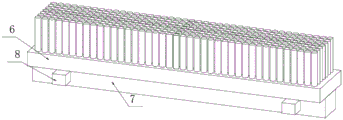
Fig. 4 is a perspective view showing a brush body according to the present utility model.
Fig. 5 is a schematic perspective view of a fixture block according to the present utility model.
In the figure: 1. an operation table; 2. a moving plate; 3. a mounting rod; 4. a support frame; 5. a mounting groove; 6. a brush main body; 7. a mounting block; 8. a clamping block; 9. a bayonet; 10. connecting a rotating rod; 11. driving a toothed bar; 12. a toothed plate; 14. a worm wheel; 15. a worm; 16. a threaded cavity; 17. a screw block; 18. a compression bar; 19. briquetting; 20. a spring; 21. a two-way electric slide rail; 22. an annular chute; 23. a clamping device; 24. a motor; 25. an electric cylinder; 26. and (5) a polishing device.
Detailed Description
The following description of the embodiments of the present utility model will be made clearly and completely with reference to the accompanying drawings, in which it is apparent that the embodiments described are only some embodiments of the present utility model, but not all embodiments. All other embodiments, which can be made by those skilled in the art based on the embodiments of the utility model without making any inventive effort, are intended to be within the scope of the utility model.
The utility model provides a precise polishing tool for a driven shaft, which is shown in fig. 1-5, and comprises an operation table 1, wherein two movable plates 2 are arranged above the operation table 1, round openings are formed in the surfaces of the opposite sides of the two movable plates 2, a mounting rod 3 is arranged in the two round openings, a support frame 4 is fixedly connected to the left side and the right side of the upper side surface of the operation table 1, the left side and the right side of the mounting rod 3 are fixedly connected with the left side and the right side of the inner wall of the support frame 4 respectively, a mounting groove 5 is formed in the upper side surface of the support frame 4, a brush main body 6 is arranged above the mounting groove 5, a mounting block 7 is fixedly connected to the lower side surface of the brush main body 6, openings are formed in the left side and the right side of the front side surface of the mounting block 7, a plurality of bayonets 9 matched with the clamping blocks 8 are formed in the front side and the rear side of the inner wall of the mounting groove 5, and a moving mechanism is arranged in the two openings.
As shown in fig. 2 and 5, two opposite sides of the inner walls of the opening are provided with sliding grooves, the inner walls of the two sliding grooves are slidably connected with one side surface of the clamping block 8 through sliding blocks, the clamping block 8 is kept stable when moving under the action of the sliding grooves, the moving mechanism comprises two connecting rotating rods 10, the lower ends of the two connecting rotating rods 10 are respectively rotationally connected with the front side and the rear side of the lower side of the inner wall of the opening, the rod walls of the two connecting rotating rods 10 are fixedly connected with driving toothed bars 11, the right side surfaces of the two clamping blocks 8 are fixedly connected with toothed plates 12, the left side surfaces of the two driving toothed bars 11 are in meshed connection with the right side surfaces of the corresponding toothed plates 12, cavities are formed in the front side and the rear side of the right side of the upper side surface of the brush main body 6, the upper ends of the two connecting rotating rods 10 penetrate through the upper side of the inner wall of the opening and the lower side surface of the brush main body 6 to the inside of the cavities, the upper ends of the two connecting rotating rods 10 are fixedly connected with worm wheels 14, the left side surfaces of the worm wheels 14 are connected with worm rods 15 in a meshed mode, opposite ends of the two worm rods 15 are rotatably connected with opposite sides of the inner wall of the cavities, all clamping blocks 8 can move under the action of a moving mechanism, and therefore when the brush main body 6 is installed, the clamping blocks 8 can move from the opening to corresponding clamping openings 9 to be clamped, and stability of the brush main body 6 is maintained.
As shown in fig. 2 and 3, opposite ends of the two worms 15 penetrate through opposite sides of the inner wall of the cavity to front and rear side surfaces of the brush main body 6 respectively, the threaded cavities 16 are formed in opposite ends of the two worms 15, the threaded blocks 17 are connected with the inner walls of the two threaded cavities 16 in a threaded manner, the pressing rods 18 are fixedly connected with the opposite side surfaces of the two threaded blocks 17, opposite ends of the two pressing rods 18 penetrate through the front side of the inner walls of the threaded cavities 16 to the front side surface of the brush main body 6, the pressing blocks 19 are fixedly connected with the opposite side surfaces of the two pressing rods 18 respectively, the springs 20 are fixedly connected with the opposite side surfaces of the two pressing blocks 19 respectively and the front and rear side surfaces of the brush main body 6, under the resilience of the springs 20, the pressing blocks 19 conveniently drive the threaded blocks 17 to move, so that when an operator loosens the pressing blocks 19, the worms 15 rotate to drive the internal moving devices to move, the clamping blocks 8 are clamped into the clamping blocks 9, grooves are formed in the upper side surfaces of the operating table 1, the inner walls of the grooves are fixedly connected with the bidirectional electric sliding rails 21, the inner walls of the bidirectional electric sliding rails 21 are connected with the lower side surfaces of the moving plates 2, and the two driven shafts are conveniently clamped by the electric sliding rails 2, and the two opposite moving distance of the opposite sides of the driven shafts are conveniently adjusted.
As shown in fig. 1, the opposite surfaces of the two moving plates 2 are provided with annular sliding grooves 22, the inner walls of the two annular sliding grooves 22 are slidably connected with clamping devices 23 through annular sliding blocks, the right side surface of the right moving plate 2 is fixedly connected with a motor 24, the output end of the motor 24 penetrates through the right side surface of the right moving plate 2 to the left side surface thereof, the output end of the right motor 24 is fixedly connected with the right side surface of the right clamping device 23, under the action of the annular sliding grooves 22, the two clamping devices 23 facilitate stable rotation processing on the moving plate 2, complete polishing of a driven shaft is facilitated, the upper side surface of the supporting frame 4 is fixedly connected with an electric cylinder 25, the output end of the electric cylinder 25 penetrates through the upper side surface of the supporting frame 4 to the inside of the supporting frame, the output end of the electric cylinder 25 is fixedly connected with a polishing device 26, and under the action of the electric cylinder 25, the polishing device 26 is conveniently driven to move to a proper processing position.
The working principle of the utility model is as follows: when the device is used, all equipment needing to be electrified in the device is connected with an external power supply, and the bidirectional electric sliding rail 21 is started to drive the two moving plates 2 to move relatively, so that the two operation tables 1 are adjusted to the position where the proper driven shafts are installed, the brush main body 6 with proper size is placed on the support frame 4, the installation block 7 is clamped into the installation groove 5 in the support frame 4, meanwhile, the pressing block 19 is pressed, the threaded block 17 on the pressing rod 18 is driven to move towards the threaded cavity 16, under the action of the threaded cavity 16 and the pressing rod 18, the worm 15 is driven to rotate, the worm wheel 14 is driven to rotate, the driving toothed bar 11 on the connecting rotating rod 10 is driven to rotate, the clamping block 8 is driven to move into the opening through the toothed plate 12, the installation block 7 under the brush main body 6 is placed in the installation groove 5 on the support frame 4, the pressing block 19 is loosened, and the device is driven to operate reversely under the rebound of the spring 20, so that the clamping block 8 is discharged from the opening, and the brush main body 6 is moved until the clamping block 8 is clamped into the corresponding bayonet 9, and the stability of the brush main body 6 is maintained;
the driven shaft is clamped through the two clamping devices 23, the motor 24 is started to drive the driven shaft to rotate and process, the electric cylinder 25 is started simultaneously, the polishing device 26 is driven to move downwards, the polishing device 26 is enabled to move to the upper portion of the driven shaft to polish the driven shaft, and the hairbrush main body 6 below cleans impurities on the surface of the driven shaft when the driven shaft rotates and polishes.
Finally, it should be noted that: the foregoing description is only illustrative of the preferred embodiments of the present utility model, and although the present utility model has been described in detail with reference to the foregoing embodiments, it will be apparent to those skilled in the art that modifications may be made to the embodiments described, or equivalents may be substituted for elements thereof, and any modifications, equivalents, improvements or changes may be made without departing from the spirit and principles of the present utility model.
Claims (7)
1. The utility model provides a precision frock of polishing of driven shaft, includes operation panel (1), its characterized in that: the utility model discloses a movable structure of the electric motor car, including operation panel (1), movable plate (2), installation piece (7), opening, both sides, mounting groove (5) have been seted up to the top of operation panel (1) be provided with two movable plate (2) respectively the opposite side surface of movable plate (2) has all offered the circle mouth, two the inside of circle mouth is provided with installation pole (3) jointly, the common fixedly connected with support frame (4) in left and right sides of operation panel (1) upside surface, both ends respectively with the left and right sides fixed connection of support frame (4) inner wall about installation pole (3), mounting groove (5) have been seted up on the upside surface of support frame (4), the top of mounting groove (5) is provided with brush main part (6), the downside fixed surface of brush main part (6) is connected with installation piece (7), the opening has all been seted up on the left and right sides of installation piece (7) front side surface, two both sides inside the opening all are provided with fixture block (8), a plurality of bayonet sockets (9) with fixture block (8) assorted about the front and back side of mounting groove (5) inner wall, two the inside of opening is provided with moving mechanism.
2. The precise polishing tool for the driven shaft according to claim 1, wherein: the opposite sides of the two inner walls of the opening are provided with sliding grooves, and the inner walls of the two sliding grooves are in sliding connection with one side surface of the clamping block (8) through sliding blocks.
3. The precise polishing tool for the driven shaft according to claim 1, wherein: the utility model provides a brush, including opening inner wall, including the front and back both sides, the front and back both sides are rotated respectively to the lower extreme of connection bull stick (10) are connected, two the pole wall of connection bull stick (10) is equal fixedly connected with drive rack bar (11), two the right side surface of fixture block (8) is equal fixedly connected with pinion rack (12), two the left side surface of drive rack bar (11) all is connected with the right side surface meshing of corresponding pinion rack (12), the cavity has all been seted up to the front and back both sides on brush main part (6) upside surface right side, two the upside of connection bull stick (10) runs through the upside of opening inner wall and the inside of brush main part (6) to the cavity, two the upper end fixedly connected with worm wheel (14) of connection bull stick (10), the left side surface meshing of worm wheel (14) is connected with worm (15), two the relative one end of worm (15) is rotated with the relative one side of cavity inner wall.
4. A driven shaft precision grinding tool according to claim 3, characterized in that: the opposite ends of the two worms (15) penetrate through the opposite sides of the inner wall of the cavity to the front side surface and the rear side surface of the brush main body (6) respectively, the threaded cavities (16) are formed in the opposite ends of the two worms (15), the threaded blocks (17) are connected with the inner wall of the threaded cavities (16) in a threaded mode, the pressing rods (18) are fixedly connected with the opposite side surfaces of the threaded blocks (17), the opposite ends of the two pressing rods (18) penetrate through the front side of the inner wall of the threaded cavities (16) to the front side surface of the brush main body (6), the pressing blocks (19) are fixedly connected with the opposite ends of the two pressing rods (18), and the springs (20) are fixedly connected with the front side surface and the rear side surface of the brush main body (6) respectively.
5. The precise polishing tool for the driven shaft according to claim 1, wherein: the automatic control device is characterized in that a groove is formed in the upper side surface of the operating platform (1), a bidirectional electric sliding rail (21) is fixedly connected to the inner wall of the groove, and the inner wall of the bidirectional electric sliding rail (21) is in sliding connection with the lower side surface of the moving plate (2) through an electric sliding block.
6. The precise polishing tool for the driven shaft according to claim 1, wherein: the annular sliding grooves (22) are formed in the surfaces of the two opposite moving plates (2), clamping devices (23) are slidably connected to the inner walls of the two annular sliding grooves (22) through annular sliding blocks, motors (24) are fixedly connected to the right side surfaces of the moving plates (2) on the right side, the output ends of the motors (24) penetrate through the right side surfaces of the moving plates (2) on the right side to the left side surfaces of the moving plates, and the output ends of the motors (24) on the right side are fixedly connected with the right side surfaces of the clamping devices (23) on the right side.
7. The precise polishing tool for the driven shaft according to claim 1, wherein: the upper side surface fixedly connected with electronic jar (25) of support frame (4), the output of electronic jar (25) runs through the upper side surface of support frame (4) to its inside, the output fixedly connected with grinding device (26) of electronic jar (25).
Priority Applications (1)
| Application Number | Priority Date | Filing Date | Title |
|---|---|---|---|
| CN202223129687.8U CN219026894U (en) | 2022-11-24 | 2022-11-24 | Precise polishing tool for driven shaft |
Applications Claiming Priority (1)
| Application Number | Priority Date | Filing Date | Title |
|---|---|---|---|
| CN202223129687.8U CN219026894U (en) | 2022-11-24 | 2022-11-24 | Precise polishing tool for driven shaft |
Publications (1)
| Publication Number | Publication Date |
|---|---|
| CN219026894U true CN219026894U (en) | 2023-05-16 |
Family
ID=86293368
Family Applications (1)
| Application Number | Title | Priority Date | Filing Date |
|---|---|---|---|
| CN202223129687.8U Active CN219026894U (en) | 2022-11-24 | 2022-11-24 | Precise polishing tool for driven shaft |
Country Status (1)
| Country | Link |
|---|---|
| CN (1) | CN219026894U (en) |
-
2022
- 2022-11-24 CN CN202223129687.8U patent/CN219026894U/en active Active
Similar Documents
| Publication | Publication Date | Title |
|---|---|---|
| CN111469033B (en) | Automatic rust cleaning robot for machine tool guide rail | |
| CN112338741A (en) | Part surface treatment device and treatment method for industrial machine production | |
| CN209551477U (en) | A kind of burr processing unit of hex bolts | |
| CN215547734U (en) | Circular bronze statue surface finish device | |
| CN219026894U (en) | Precise polishing tool for driven shaft | |
| CN112935982A (en) | Effectual window frame burr treatment device of burring | |
| CN113601361A (en) | Steel surface rust removal device and using method thereof | |
| CN209831253U (en) | Hand-held type miniature lacquer ware grinding device | |
| CN115592211A (en) | Gear tooth profile modification device for gear transmission device | |
| CN212824529U (en) | Deburring equipment | |
| CN210703960U (en) | Main rail processing equipment convenient to fully polish | |
| CN210790234U (en) | Broach removes iron fillings device | |
| CN216656609U (en) | Grinding device for deburring of gears | |
| CN216608375U (en) | Bilateral edging equipment of toughened glass | |
| CN215846120U (en) | Grinding device for deburring of gears | |
| CN220178866U (en) | Spring end face polishing equipment | |
| CN213970225U (en) | Milling machine is used in processing of accurate car mould | |
| CN112846993B (en) | Copper pipe port processing polishing deburring device | |
| CN215547664U (en) | Rotating shaft polishing equipment for producing LED glass cleaning brush | |
| CN211940246U (en) | A polisher for auto parts are polished | |
| CN210909485U (en) | Excircle polishing device for hydraulic support maintenance | |
| CN216359338U (en) | Manual milling machine with convenient clearance function | |
| CN219379972U (en) | Horizontal migration type chip removal cleaning device | |
| CN220463322U (en) | Engineering machine tool accessory handles and equips | |
| CN219882068U (en) | Radial axial floating deburring tool |
Legal Events
| Date | Code | Title | Description |
|---|---|---|---|
| GR01 | Patent grant | ||
| GR01 | Patent grant | ||
| TR01 | Transfer of patent right |
Effective date of registration: 20231218 Address after: 224500 North Industrial Park, Economic Development Zone, Binhai County, Yancheng City, Jiangsu Province (No. 7 Oubei Industrial Park) Patentee after: Yancheng Yingeng Intelligent Manufacturing Co.,Ltd. Address before: 215000 Building 2, 458 Xinfeng Road, Xukou Town, Wuzhong District, Suzhou City, Jiangsu Province Patentee before: Suzhou Yingeng Machinery Co.,Ltd. |
|
| TR01 | Transfer of patent right |