CN219019413U - Electric power metering cabinet ventilation unit - Google Patents
Electric power metering cabinet ventilation unit Download PDFInfo
- Publication number
- CN219019413U CN219019413U CN202223521654.8U CN202223521654U CN219019413U CN 219019413 U CN219019413 U CN 219019413U CN 202223521654 U CN202223521654 U CN 202223521654U CN 219019413 U CN219019413 U CN 219019413U
- Authority
- CN
- China
- Prior art keywords
- fixedly connected
- electric power
- metering cabinet
- power metering
- wall
- Prior art date
- Legal status (The legal status is an assumption and is not a legal conclusion. Google has not performed a legal analysis and makes no representation as to the accuracy of the status listed.)
- Active
Links
Images


Landscapes
- Cooling Or The Like Of Electrical Apparatus (AREA)
Abstract
The utility model relates to the technical field of power equipment and discloses a ventilation device of an electric power metering cabinet, which comprises an electric power metering cabinet, wherein the outer wall of the electric power metering cabinet is fixedly connected with a cooling mechanism, the inner wall of the electric power metering cabinet is fixedly connected with a heat dissipation mechanism, one side of the electric power metering cabinet is hinged with an overhaul mechanism, the heat dissipation mechanism comprises a fixed frame, a second fan, a mounting hole, an air outlet pipe, an air inlet pipe and an evaporator, a rotating shaft of the inner wall of the fixed frame is connected with the second fan, the mounting hole is formed in the outer wall of the fixed frame, one side of the fixed frame is fixedly connected with the evaporator, one side of the evaporator is fixedly connected with the air outlet pipe, one side of the evaporator is fixedly connected with the air inlet pipe, cold air generated by the evaporator is blown into the electric power metering cabinet by the second fan to dissipate heat, damage to parts caused by overhigh temperature is prevented, the service life of the parts is prolonged, and economic consumption of users is reduced.
Description
Technical Field
The utility model relates to the technical field of power equipment, in particular to a ventilation device of an electric power metering cabinet.
Background
The electric power metering cabinet is a cabinet body for installing an electric energy meter and controlling the electric energy meter, and becomes necessary equipment of electric power equipment due to popularization of electric power and basic demands of life.
For example, chinese patent number is: the utility model discloses an electric power metering cabinet ventilation device which comprises a metering cabinet body and a through hole formed in the inner wall of one side of the bottom of the metering cabinet body, wherein a mounting plate is arranged right below the through hole, the top of the mounting plate is fixedly connected with a motor, an output shaft of the motor is fixedly connected with a rotating shaft, an inclined plate welded on the inner wall of the metering cabinet body is arranged above the through hole, the top end of the rotating shaft penetrates through the inclined plate to extend to the upper part of the inclined plate and is welded with a first conical gear, a plurality of fan blades are fixedly connected to the outer side of the rotating shaft and are all positioned in the through hole, and a strip-shaped groove is formed in the inner wall of one side of the metering cabinet body. The utility model has reasonable design, is convenient for blowing the external air into the metering cabinet body, and the air flow can be uniformly blown into the metering cabinet body, thereby reducing blowing dead angles, facilitating the heat dissipation work of the metering cabinet body, avoiding damage caused by overheat in the metering cabinet body and being beneficial to use.
However, the prior art has some problems:
1. most of the existing electric power metering cabinets have relatively poor internal heat dissipation effect and relatively quick internal circuit aging.
2. Most of the existing electric power metering cabinets have poor ventilation effect and are easy to accumulate dust.
Disclosure of Invention
(one) solving the technical problems
Aiming at the defects of the prior art, the utility model provides the ventilation device of the electric power metering cabinet, which has the advantages of increasing heat dissipation, fast air circulation and the like, and solves the problems in the background art.
(II) technical scheme
In order to achieve the purpose of increasing heat dissipation and air circulation speed, the utility model provides the following technical scheme: the utility model provides an electric power metering cabinet ventilation unit, includes the electric power metering cabinet, the outer wall fixedly connected with cooling body of electric power metering cabinet, the inner wall fixedly connected with cooling body of electric power metering cabinet, one side hinged joint of electric power metering cabinet has maintenance mechanism.
The utility model discloses a heat dissipation mechanism, including fixed frame, second fan, mounting hole, outlet duct, intake pipe and evaporimeter, fixed frame's inner wall pivot is connected with the second fan, the mounting hole has been seted up to fixed frame's outer wall, one side fixedly connected with evaporimeter of fixed frame, one side fixedly connected with outlet duct of evaporimeter, one side fixedly connected with intake pipe of evaporimeter, the cold air that the evaporimeter produced is blown to inside the electric power measurement cabinet by the second fan, dispels the heat to inside, prevents that the high temperature from causing the damage to the spare part, increases the life of part, reduces user's economic consumption.
Preferably, the cooling mechanism comprises a compressor, a hot air pipe, a connecting pipe, a cooling frame, a condenser, a liquid pipe, a heat dissipation frame and a first fan, wherein the inner wall of the cooling frame is fixedly connected with the compressor, one side of the compressor is fixedly connected with the hot air pipe, one side of the compressor is fixedly connected with the connecting pipe, one end of the connecting pipe is fixedly connected with the condenser, one side of the condenser is fixedly connected with the liquid pipe, one side of the condenser is fixedly connected with the first fan, the outer wall of the cooling frame is provided with the heat dissipation frame, the compressor compresses and liquefies freon, and the freon is further cooled through the condenser, so that the work of the heat dissipation mechanism achieves the maximum effect, and the heat dissipation effect on the electric power metering cabinet is enhanced.
Preferably, the maintenance mechanism comprises an access door, a handle and a heat dissipation hole, wherein the handle is fixedly connected to the outer wall of the access door, the heat dissipation hole is formed in the outer wall of the access door, the inside of the electric power metering cabinet is conveniently inspected and maintained, and the ventilation effect of the inner wall of the electric power metering cabinet is enhanced by the heat dissipation hole.
Preferably, the top fixedly connected with ventilation fan of electric power measurement cabinet, ventilation effect of electric power measurement cabinet is strengthened to the axis coincidence of ventilation fan's axis and electric power measurement cabinet, and the louvre forms complete wind channel with ventilation fan for the circulation of air.
Preferably, fixed frame one side is through bolt and mounting hole and evaporimeter one side fixed connection, fixed frame passes through the inner wall fixed connection of bolt and electric power measurement cabinet, can conveniently overhaul mounting hole and evaporimeter through bolt fixed connection, also conveniently clear up the dust on mounting hole and the evaporimeter.
Preferably, one end fixedly connected with hot air pipe of outlet duct, the one end fixedly connected with liquid pipe of intake pipe carries out cyclic utilization with the inside freon of device, and two mechanisms of direct connection reduce the loss of intermediate temperature.
Preferably, one side of the fixed frame is rounded, and the rounded corners on the fixed frame are rounded inwards, so that the protrusion of the bolts is reduced, and the parts are prevented from colliding with the bolts.
Preferably, the evaporator forms a communication structure with the condenser through an air outlet pipe, an air inlet pipe, a compressor, a hot air pipe, a connecting pipe and a liquid pipe, and the heat dissipation effect is prevented from being reduced due to the fact that freon is leaked.
(III) beneficial effects
Compared with the prior art, the utility model provides the ventilation device of the electric power metering cabinet, which has the following beneficial effects:
1. this electric power metering cabinet ventilation unit, through the cooling mechanism who sets up, the cold air that the evaporimeter produced is blown inside the electric power metering cabinet by the second fan, dispels the heat to inside, prevents that the high temperature from causing the damage to the spare part, increases the life of part, reduces user's economic consumption to this electric power metering cabinet ventilation unit's practicality has been improved.
2. This electric power metering cabinet ventilation unit, through the cooling body who sets up, the compressor compresses the liquefaction with freon, further cooling down with freon through the condenser, guarantees that cooling body's work reaches maximum effect, the reinforcing is to the radiating effect of electric power metering cabinet.
3. This electric power metering cabinet ventilation unit, through the maintenance mechanism that sets up, the convenience is inside to be inspected and maintain the electric power metering cabinet, and the ventilation effect of electric power metering cabinet inner wall has been strengthened to the louvre.
Drawings
FIG. 1 is a cross-sectional view of the present utility model;
FIG. 2 is a cross-sectional view of the cooling mechanism of the present utility model;
FIG. 3 is a schematic view of a connection structure of a heat dissipation frame and a first fan according to the present utility model;
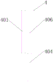
FIG. 4 is a front view of a heat dissipating mechanism according to the present utility model;
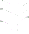
FIG. 5 is a side view of a heat dissipating mechanism according to the present utility model;
fig. 6 is a side view of the present utility model.
In the figure: 1. a cooling mechanism; 101. a compressor; 102. a hot air pipe; 103. a connecting pipe; 104. a cooling frame; 105. a condenser; 106. a liquid tube; 107. a heat dissipation frame; 108. a first fan; 2. an electric power metering cabinet; 3. a ventilation fan; 4. a heat dissipation mechanism; 401. a fixed frame; 402. a second fan; 403. a mounting hole; 404. an air outlet pipe; 405. an air inlet pipe; 406. an evaporator; 5. an overhaul mechanism; 501. an access door; 502. a handle; 503. and the heat dissipation holes.
Detailed Description
The following description of the embodiments of the present utility model will be made clearly and completely with reference to the accompanying drawings, in which it is apparent that the embodiments described are only some embodiments of the present utility model, but not all embodiments. All other embodiments, which can be made by those skilled in the art based on the embodiments of the utility model without making any inventive effort, are intended to be within the scope of the utility model.
Example 1
The preferred embodiment of the ventilation device for the electric power metering cabinet provided by the utility model is shown in fig. 1 to 6: the utility model provides an electric power metering cabinet ventilation unit, includes electric power metering cabinet 2, and the outer wall fixedly connected with cooling body 1 of electric power metering cabinet 2, the inner wall fixedly connected with cooling body 4 of electric power metering cabinet 2, one side hinged joint of electric power metering cabinet 2 has maintenance mechanism 5.
The heat dissipation mechanism 4 includes fixed frame 401, second fan 402, the mounting hole 403, outlet duct 404, intake pipe 405 and evaporimeter 406, fixed frame 401's inner wall pivot is connected with second fan 402, fixed frame 401's outer wall has seted up mounting hole 403, one side fixedly connected with evaporimeter 406 of fixed frame 401, one side fixedly connected with outlet duct 404 of evaporimeter 406, one side fixedly connected with intake pipe 405 of evaporimeter 406, the cold air that evaporimeter 406 produced is blown to the electric power measurement cabinet inside by second fan 402, dispel the heat to inside, prevent that the high temperature from causing the damage to the spare part, increase the life of part, reduce user's economic consumption.
In this embodiment, cooling mechanism 1 includes compressor 101, hot air pipe 102, connecting pipe 103, cooling frame 104, condenser 105, liquid pipe 106, heat dissipation frame 107 and first fan 108, cooling frame 104's inner wall fixedly connected with compressor 101, one side fixedly connected with hot air pipe 102 of compressor 101, one side fixedly connected with connecting pipe 103 of compressor 101, the one end fixedly connected with condenser 105 of connecting pipe 103, one side fixedly connected with liquid pipe 106 of condenser 105, one side fixedly connected with first fan 108 of condenser 105, cooling frame 107 has been seted up to cooling frame 104's outer wall, compressor 101 compresses the liquefaction with freon, further cooling down with freon through condenser 105, guarantee that cooling mechanism 4's work reaches maximum effect, the radiating effect to the electric power measurement cabinet is strengthened.
Example 2
On the basis of embodiment 1, a preferred embodiment of the ventilation device for an electric power metering cabinet provided by the utility model is shown in fig. 1 to 6: the access mechanism 5 comprises an access door 501, a handle 502 and a heat dissipation hole 503, wherein the handle 502 is fixedly connected with the outer wall of the access door 501, the heat dissipation hole 503 is formed in the outer wall of the access door 501, the inside of the electric power metering cabinet is conveniently inspected and maintained, and the ventilation effect of the inner wall of the electric power metering cabinet is enhanced by the heat dissipation hole 503.
In this embodiment, ventilation fan 3 is fixedly connected with at the top of electric power metering cabinet 2, and the axis of ventilation fan 3 coincides with the axis of electric power metering cabinet 2, strengthens the ventilation effect of electric power metering cabinet, and louvre 503 forms complete wind channel with ventilation fan 3 for the circulation of air.
Further, fixed frame 401 one side passes through bolt and mounting hole 403 and evaporator 406 one side fixed connection, and fixed frame 401 passes through the inner wall fixed connection of bolt and electric power measurement cabinet 2, can conveniently overhaul mounting hole 403 and evaporator 406 through bolt fixed connection, also conveniently clear up the dust on mounting hole 403 and the evaporator 406.
Furthermore, one end of the air outlet pipe 404 is fixedly connected with the hot air pipe 102, one end of the air inlet pipe 405 is fixedly connected with the liquid pipe 106, the freon in the device is recycled, and the two mechanisms are directly connected to reduce the loss of the intermediate temperature.
In addition, one side of the fixed frame 401 is rounded, and the rounded corners on the fixed frame 401 are rounded inwards, so that the protrusion of the bolts is reduced to prevent the parts from colliding with the bolts, and the evaporator 406 forms a communication structure with the condenser 105 through the air outlet pipe 404, the air inlet pipe 405, the compressor 101, the hot air pipe 102, the connecting pipe 103 and the liquid pipe 106, so that the reduction of the heat dissipation effect caused by the Freon leakage is prevented.
The electrical components are all connected with an external main controller and 220V mains supply, and the main controller can be conventional known equipment for controlling a computer and the like.
When the electric power metering cabinet is used, the compressor 101 is started to compress and liquefy freon, the condenser 105 and the first fan 108 cool the liquefied freon, the cooled liquefied freon enters the evaporator 406 through the liquid pipe 106 and the air inlet pipe 405, vaporization absorbs heat, the second fan 402 blows cold air into the electric power metering cabinet 2 to cool and dissipate heat, and the freon enters the compressor 101 through the air outlet pipe 404 and the hot air pipe 102 to perform the next cycle.
In summary, the ventilation device of the electric power metering cabinet can achieve the purposes of increasing heat dissipation and air circulation.
It is noted that relational terms such as first and second, and the like are used solely to distinguish one entity or action from another entity or action without necessarily requiring or implying any actual such relationship or order between such entities or actions. Moreover, the terms "comprises," "comprising," or any other variation thereof, are intended to cover a non-exclusive inclusion, such that a process, method, article, or apparatus that comprises a list of elements does not include only those elements but may include other elements not expressly listed or inherent to such process, method, article, or apparatus.
Although embodiments of the present utility model have been shown and described, it will be understood by those skilled in the art that various changes, modifications, substitutions and alterations can be made therein without departing from the principles and spirit of the utility model, the scope of which is defined in the appended claims and their equivalents.
Claims (8)
1. The utility model provides an electric power metering cabinet ventilation unit, includes electric power metering cabinet (2), its characterized in that: the electric power metering cabinet is characterized in that the outer wall of the electric power metering cabinet (2) is fixedly connected with a cooling mechanism (1), the inner wall of the electric power metering cabinet (2) is fixedly connected with a heat dissipation mechanism (4), and one side of the electric power metering cabinet (2) is hinged with an overhaul mechanism (5);
the heat dissipation mechanism (4) comprises a fixed frame (401), a second fan (402), a mounting hole (403), an air outlet pipe (404), an air inlet pipe (405) and an evaporator (406), wherein the second fan (402) is connected with a rotating shaft of the inner wall of the fixed frame (401), the mounting hole (403) is formed in the outer wall of the fixed frame (401), the evaporator (406) is fixedly connected to one side of the fixed frame (401), the air outlet pipe (404) is fixedly connected to one side of the evaporator (406), and the air inlet pipe (405) is fixedly connected to one side of the evaporator (406).
2. A power metering cabinet ventilation apparatus as claimed in claim 1, wherein: the cooling mechanism (1) comprises a compressor (101), a hot air pipe (102), a connecting pipe (103), a cooling frame (104), a condenser (105), a liquid pipe (106), a heat dissipation frame (107) and a first fan (108), wherein the inner wall of the cooling frame (104) is fixedly connected with the compressor (101), one side of the compressor (101) is fixedly connected with the hot air pipe (102), one side of the compressor (101) is fixedly connected with the connecting pipe (103), one end of the connecting pipe (103) is fixedly connected with the condenser (105), one side of the condenser (105) is fixedly connected with the liquid pipe (106), one side of the condenser (105) is fixedly connected with the first fan (108), and the outer wall of the cooling frame (104) is provided with the heat dissipation frame (107).
3. A power metering cabinet ventilation apparatus as claimed in claim 1, wherein: the overhaul mechanism (5) comprises an overhaul door (501), a handle (502) and a heat dissipation hole (503), wherein the handle (502) is fixedly connected to the outer wall of the overhaul door (501), and the heat dissipation hole (503) is formed in the outer wall of the overhaul door (501).
4. A power metering cabinet ventilation apparatus as claimed in claim 1, wherein: the top fixedly connected with ventilation fan (3) of electric power measurement cabinet (2), the axis of ventilation fan (3) coincides with the axis of electric power measurement cabinet (2).
5. A power metering cabinet ventilation apparatus as claimed in claim 1, wherein: one side of the fixed frame (401) is fixedly connected with one side of the evaporator (406) through bolts and mounting holes (403), and the fixed frame (401) is fixedly connected with the inner wall of the electric power metering cabinet (2) through bolts.
6. A power metering cabinet ventilation apparatus as claimed in claim 1, wherein: one end of the air outlet pipe (404) is fixedly connected with the hot air pipe (102), and one end of the air inlet pipe (405) is fixedly connected with the liquid pipe (106).
7. A power metering cabinet ventilation apparatus as claimed in claim 1, wherein: one side of the fixed frame (401) is rounded, and the round corners on the fixed frame (401) are inwardly rounded.
8. A power metering cabinet ventilation apparatus as claimed in claim 1, wherein: the evaporator (406) and the condenser (105) form a communication structure through an air outlet pipe (404), an air inlet pipe (405), a compressor (101), a hot air pipe (102), a connecting pipe (103) and a liquid pipe (106).
Priority Applications (1)
| Application Number | Priority Date | Filing Date | Title |
|---|---|---|---|
| CN202223521654.8U CN219019413U (en) | 2022-12-28 | 2022-12-28 | Electric power metering cabinet ventilation unit |
Applications Claiming Priority (1)
| Application Number | Priority Date | Filing Date | Title |
|---|---|---|---|
| CN202223521654.8U CN219019413U (en) | 2022-12-28 | 2022-12-28 | Electric power metering cabinet ventilation unit |
Publications (1)
| Publication Number | Publication Date |
|---|---|
| CN219019413U true CN219019413U (en) | 2023-05-12 |
Family
ID=86238301
Family Applications (1)
| Application Number | Title | Priority Date | Filing Date |
|---|---|---|---|
| CN202223521654.8U Active CN219019413U (en) | 2022-12-28 | 2022-12-28 | Electric power metering cabinet ventilation unit |
Country Status (1)
| Country | Link |
|---|---|
| CN (1) | CN219019413U (en) |
-
2022
- 2022-12-28 CN CN202223521654.8U patent/CN219019413U/en active Active
Similar Documents
| Publication | Publication Date | Title |
|---|---|---|
| CN219019413U (en) | Electric power metering cabinet ventilation unit | |
| CN211530846U (en) | Uninterrupted power source equipment for data center | |
| CN217357788U (en) | Energy-conserving effectual ice and water machine | |
| CN207305251U (en) | A kind of frequency-conversion control cabinet heat dissipation tank | |
| CN207280001U (en) | A kind of vehicle-mounted multi-temperature zone refrigerator | |
| CN215264662U (en) | Desktop computer host shell with circulating heat dissipation function | |
| CN211781680U (en) | Temperature control adjusting device of air conditioning refrigerating unit | |
| CN210714827U (en) | Device for cooling engine | |
| CN211557815U (en) | Electric machine room cooling system | |
| CN207801482U (en) | Low-voltage reactive power compensation device | |
| CN219019181U (en) | Heat dissipation type control cabinet of wind turbine generator system | |
| CN208205299U (en) | A kind of air-conditioning | |
| CN219600913U (en) | Engine protection cover for explosion-proof loader | |
| CN205783342U (en) | A kind of ceiling air conditioner | |
| CN213421512U (en) | Quick cooling structure for air source heat pump | |
| CN215808916U (en) | Central air conditioning outdoor unit with efficient heat dissipation structure | |
| CN215579934U (en) | Weak current cabinet convenient to heat dissipation | |
| CN218678799U (en) | Frequency conversion cabinet | |
| CN219318721U (en) | Environment-friendly and energy-saving structure of refrigeration equipment | |
| CN219868584U (en) | Air-cooled screw type water chiller | |
| CN211529087U (en) | Self-cooling machine case of computer | |
| CN214897982U (en) | Heat dissipation equipment of high-capacity rectifier transformer | |
| CN216218507U (en) | Laboratory computer lab management equipment that ventilation cooling is good | |
| CN215547213U (en) | Cooling device for coolant of numerical control machine tool for machining medical instrument accessories | |
| CN216054164U (en) | Rectifier transformer with double-layer horizontal saturable reactor |
Legal Events
| Date | Code | Title | Description |
|---|---|---|---|
| GR01 | Patent grant | ||
| GR01 | Patent grant |