CN219005300U - Vertical engraving and milling machine clamp - Google Patents
Vertical engraving and milling machine clamp Download PDFInfo
- Publication number
- CN219005300U CN219005300U CN202222622737.XU CN202222622737U CN219005300U CN 219005300 U CN219005300 U CN 219005300U CN 202222622737 U CN202222622737 U CN 202222622737U CN 219005300 U CN219005300 U CN 219005300U
- Authority
- CN
- China
- Prior art keywords
- sliding
- fixed
- milling machine
- mounting frame
- engraving
- Prior art date
- Legal status (The legal status is an assumption and is not a legal conclusion. Google has not performed a legal analysis and makes no representation as to the accuracy of the status listed.)
- Active
Links
Images


Classifications
-
- Y—GENERAL TAGGING OF NEW TECHNOLOGICAL DEVELOPMENTS; GENERAL TAGGING OF CROSS-SECTIONAL TECHNOLOGIES SPANNING OVER SEVERAL SECTIONS OF THE IPC; TECHNICAL SUBJECTS COVERED BY FORMER USPC CROSS-REFERENCE ART COLLECTIONS [XRACs] AND DIGESTS
- Y02—TECHNOLOGIES OR APPLICATIONS FOR MITIGATION OR ADAPTATION AGAINST CLIMATE CHANGE
- Y02P—CLIMATE CHANGE MITIGATION TECHNOLOGIES IN THE PRODUCTION OR PROCESSING OF GOODS
- Y02P70/00—Climate change mitigation technologies in the production process for final industrial or consumer products
- Y02P70/10—Greenhouse gas [GHG] capture, material saving, heat recovery or other energy efficient measures, e.g. motor control, characterised by manufacturing processes, e.g. for rolling metal or metal working
Abstract
The utility model discloses a vertical engraving and milling machine fixture, which belongs to the technical field of engraving and milling machines and comprises a mounting frame, wherein rotating shafts are symmetrically arranged in the mounting frame, worms are fixed in the middle positions of the rotating shafts, sliding blocks are symmetrically arranged on the outer sides of the rotating shafts and are in threaded connection with the rotating shafts, sliding rods are fixed at the tops of the sliding blocks, sliding holes are formed in the tops of the mounting frame, the sliding rods are in sliding connection with the sliding holes, clamping plates are fixed at the tops of the sliding rods, adjusting assemblies are arranged on the clamping plates, and a sleeve is rotatably connected to the inner top wall of the mounting frame. According to the utility model, through the matched use of the mounting frame, the rotating shaft, the sliding block, the sliding rod, the sliding hole, the worm, the sleeve, the worm wheel, the fixing rod, the ejection block, the limiting rod, the limiting hole, the placing plate and the clamping plate, the purpose of taking out the workpiece more conveniently and more effort-saving is achieved, the problem that the workpiece is inconvenient to take out due to too close adhesion between the workpiece and the bottom is avoided, and convenience is provided for the operation and use of people.
Description
Technical Field
The utility model relates to the technical field of engraving and milling machines, in particular to a clamp of a vertical engraving and milling machine.
Background
The engraving and milling machine is a numerical control machine tool, is generally considered to be a numerical control milling machine using a small cutter, a high-power and high-speed spindle motor, has the advantages of engraving and milling, can help the engraving and milling machine to fill the gap between the engraving and milling machine and the high-power spindle motor if the hardness of a processed material is relatively high, can be engraved or milled, is a high-efficiency and high-precision numerical control machine tool, is firstly proposed and realized by a good iron, has a wider application range, is widely used for finishing the rough finishing of a die core of a precise die at one time, is used for batch processing of a die red copper electrode and an aluminum product, manufacturing of a shoe die, is used for processing a jig, has the advantages of high cost performance of the engraving and milling machine, high processing speed and good finish of the processed product, and is more and more important in the machine tool processing industry, and is an essential processing link for industrial automation.
The application number is as follows: 201922086876.3, a clamp for a vertical engraving and milling machine, is beneficial: 1. according to the utility model, the fixing device is adopted, so that the materials are conveniently fixed through the fixing rod, the phenomenon that the operation of equipment is influenced by loosening of the materials during processing is avoided, and the stability of the equipment is effectively improved by the application of the device. 2. According to the utility model, the reset device is adopted, so that the force borne by the fixed rod is conveniently transmitted to the compression spring through the reset block, the fixed rod is conveniently driven to reciprocate, the trouble that the control rod is required to be manually pushed when materials are fixed each time is avoided, and the device is applied to effectively improve the working efficiency of equipment.
Similar to the above-mentioned application, there are currently disadvantages:
the common vertical engraving and milling machine clamp can take the workpiece off the clamp after the workpiece is machined, but the bottom of some workpieces is close to the bottom of the clamp, so that inconvenience is brought to taking out the workpiece.
A vertical engraving and milling machine fixture is designed for the purpose to optimize the problems.
Disclosure of Invention
The utility model mainly aims to provide a vertical engraving and milling machine clamp for solving the related technical problems in the background technology.
The aim of the utility model can be achieved by adopting the following technical scheme:
the utility model provides a vertical carving mills quick-witted anchor clamps, includes the installing frame, the inside symmetry of installing frame is provided with the pivot, the intermediate position of pivot all is fixed with the worm, the outside of pivot all is provided with the slider symmetrically, and slider and pivot threaded connection, the top of slider all is fixed with the slide bar, the slide hole has been seted up at the top of installing frame, slide bar and slide hole sliding connection, the top of slide bar all is fixed with splint, be provided with adjusting part on the splint, the interior roof rotation of installing frame is connected with the sleeve pipe, sheathed tube bottom is fixed with the worm wheel, and worm wheel and worm meshing, sheathed tube inside threaded connection has the dead lever, the top of dead lever is fixed with ejecting piece, the bottom symmetry of ejecting piece is provided with the gag lever post, the gag lever post has been seted up to the top symmetry of installing frame, and gag lever post sliding connection, the top symmetry of installing frame is provided with places the board.
Preferably: the adjusting component comprises a sliding groove, sliding pipes, a screw rod and a limiting block, wherein the sliding groove is respectively arranged at the bottom of the clamping plate, the limiting block is respectively arranged at the top of the sliding rod, the limiting block is in sliding connection with the sliding groove, the sliding pipes are respectively fixed on one sides of the clamping plates, a loop bar is sleeved between the sliding pipes, the screw rod is respectively fixed at the middle position of one side of the clamping plates, and the adjusting pipe is connected between the screw rods in a threaded mode.
Preferably: the top of placing the board and the top of ejecting piece all are provided with the blotter, and the blotter is the rubber pad.
Preferably: the inner sides of the clamping plates are provided with friction increasing pads, and one sides of the friction increasing pads are provided with anti-skid patterns.
Preferably: the mounting plates are arranged on two sides of the mounting frame, and bolts are arranged on the mounting plates.
Preferably: one end of the rotating shaft is fixed with a rotating handle, and an anti-slip layer is arranged on the outer side of the rotating handle.
The beneficial effects of the utility model are as follows:
according to the clamp of the vertical engraving and milling machine, through the matched use of the mounting frame, the rotating shaft, the sliding blocks, the sliding rods, the sliding holes, the worm, the sleeve, the worm wheel, the fixing rod, the ejection block, the limiting rod, the limiting holes, the placing plate and the clamping plates, the sliding blocks are respectively driven to move towards the positions of middle workpieces after the rotating shaft is rotated, meanwhile, the sliding rods and the clamping plates at the tops are driven to move towards the two sides of the workpieces, the worm in the middle can drive the worm wheel and the top sleeve to rotate when the rotating shaft rotates, and the fixing rod is driven to eject the workpieces on the placing plate to a certain height under the limiting of the limiting rod and the limiting holes, so that the purpose of taking out the workpieces more conveniently and conveniently is achieved, the problem that the workpieces are inconvenient to take out due to the fact that the workpieces are attached to the bottoms are too close is avoided, and convenience is provided for operation and use of people; through the cooperation of spout, stopper, slide tube, loop bar, screw rod and regulation pipe, according to the length of work piece, rotatory regulation pipe makes the screw rod promote splint respectively and carries out the back or remove in opposite directions under the spacing effect of stopper and spout to the work piece of centre gripping different length has strengthened the flexibility of this carving and milling machine anchor clamps, and application scope is wider, thereby has improved the suitability of this vertical carving and milling machine anchor clamps.
Drawings
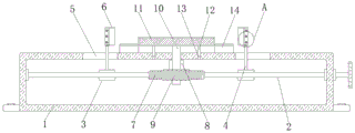
FIG. 1 is a front cross-sectional view of the present utility model;
FIG. 2 is an enlarged view of the structure of FIG. 1A according to the present utility model;
fig. 3 is a schematic view of the connection of the clamping plate and the chute of the present utility model.
In the figure: 1. a mounting frame; 2. a rotating shaft; 3. a slide block; 4. a slide bar; 5. a slide hole; 6. an adjustment assembly; 7. a worm; 8. a sleeve; 9. a worm wheel; 10. a fixed rod; 11. an ejection block; 12. a limit rod; 13. a limiting hole; 14. placing a plate; 15. a clamping plate; 16. a chute; 17. a limiting block; 18. a slide tube; 19. a loop bar; 20. a screw; 21. and (5) adjusting the pipe.
Detailed Description
In order to make the technical solution of the present utility model more clear and clear to those skilled in the art, the present utility model will be described in further detail with reference to examples and drawings, but the embodiments of the present utility model are not limited thereto.
Example 1
As shown in fig. 1-3, this embodiment provides a vertical engraving and milling machine fixture, including installing frame 1, installing frame 1's inside symmetry is provided with pivot 2, the intermediate position of pivot 2 all is fixed with worm 7, pivot 2's outside all is provided with slider 3 symmetrically, and slider 3 and pivot 2 threaded connection, slider 3's top all is fixed with slide bar 4, slide hole 5 has been seted up at installing frame 1's top, slide bar 4 and slide hole 5 sliding connection, slide bar 4's top all is fixed with splint 15, be provided with adjusting part 6 on splint 15, installing frame 1's inner roof rotates and is connected with sleeve pipe 8, sleeve pipe 8's bottom is fixed with worm wheel 9, and worm wheel 9 meshes with worm 7, sleeve pipe 8's internal thread connection has dead lever 10, the top of dead lever 10 is fixed with ejector pad 11, ejector pad 11's bottom symmetry is provided with gag lever 12, limit hole 13 has been seted up symmetrically at installing frame 1's top, and limit lever 12 sliding connection, installing frame 1's top symmetry is provided with and places board 14, adjusting part 6 includes spout 16, slide tube 18, stopper 17 and stopper 17 are fixed with splint 15 respectively, the spout 16 is fixed with the stopper 15 at the bottom of slide tube 20 respectively, the top is fixed with the stopper 20 between splint 16 and the top is connected with the slide bar 20, the top of the boss is fixed with the screw tube respectively, the top is connected with the boss 20, respectively, the top is fixed with the top of stopper is connected with the 15, and is connected with the top of stopper 20.
Through the cooperation of the mounting frame 1, the rotating shaft 2, the sliding block 3, the sliding rod 4, the sliding hole 5, the worm 7, the sleeve pipe 8, the worm wheel 9, the fixing rod 10, the ejection block 11, the limiting rod 12, the limiting hole 13, the placing plate 14 and the clamping plate 15, the rotating shaft 2 can respectively drive the sliding block 3 to move towards the middle workpiece, meanwhile, the sliding rod 4 and the clamping plate 15 at the top are driven to move towards two sides of the workpiece, the worm 7 in the middle can drive the worm wheel 9 and the top sleeve pipe 8 to rotate when the rotating shaft 2 rotates, and the fixing rod 10 is driven to eject the workpiece on the placing plate 14 to a certain height under the limit of the limiting rod 12 and the limiting hole 13, so that the purposes of saving more force and conveniently taking out the workpiece are achieved, the problem that the workpiece is inconvenient to take out due to the fact that the workpiece is attached to the bottom is too close is avoided, and convenience is provided for the operation and use of people; through the cooperation of spout 16, stopper 17, slide tube 18, loop bar 19, screw rod 20 and regulation pipe 21, according to the length of work piece, rotatory regulation pipe 21 makes screw rod 20 promote splint 15 respectively and moves backward or in opposite directions under the spacing effect of stopper 17 and spout 16 to the work piece of centre gripping different length has strengthened the flexibility of this carving and milling machine anchor clamps, and application scope is wider, thereby has improved the suitability of this vertical carving and milling machine anchor clamps.
Example two
In this embodiment, as shown in fig. 1 to 3, the top of the placement plate 14 and the top of the ejection block 11 are both provided with a cushion pad, and the cushion pad is a rubber pad.
The arrangement of the buffer pad not only increases the stability of clamping the bottom of the workpiece, but also avoids abrasion between the workpiece and the bottom in the machining process.
In this embodiment, friction increasing pads are disposed on the inner sides of the clamping plates 15, and anti-skid patterns are disposed on one sides of the friction increasing pads.
The friction force between the clamping plate 15 and the outer side of the workpiece is increased through the friction increasing pad and the anti-skid patterns, so that the clamping firmness is improved.
In this embodiment, mounting plates are provided on both sides of the mounting frame 1, and bolts are provided on the mounting plates.
The fixture of the engraving and milling machine is convenient to install and fix through the arrangement of the mounting plate and the bolts.
In this embodiment, a rotating handle is fixed at one end of the rotating shaft 2, and an anti-slip layer is provided at the outer side of the rotating handle.
The friction between one end of the rotating shaft 2 and the hand is increased through the arrangement of the rotating handle and the anti-slip layer, so that the use is convenient.
The above description is merely a further embodiment of the present utility model, but the protection scope of the present utility model is not limited thereto, and any person skilled in the art will be able to apply equivalents and modifications according to the technical solution and the concept of the present utility model within the scope of the present utility model disclosed in the present utility model.
Claims (6)
1. The utility model provides a vertical carving mills quick-witted anchor clamps which characterized in that: including installing frame (1), the inside symmetry of installing frame (1) is provided with pivot (2), the intermediate position of pivot (2) all is fixed with worm (7), the outside of pivot (2) all is provided with slider (3) symmetrically, and slider (3) and pivot (2) threaded connection, slide bar (4) are all fixed with at the top of slider (3), slide hole (5) have been seted up at the top of installing frame (1), slide bar (4) and slide hole (5) sliding connection, the top of slide bar (4) all is fixed with splint (15), be provided with adjusting part (6) on splint (15), the interior roof rotation of installing frame (1) is connected with sleeve pipe (8), the bottom of sleeve pipe (8) is fixed with worm wheel (9), and worm wheel (9) and worm (7) meshing, the internal thread connection of sleeve pipe (8) has dead lever (10), the top of dead lever (10) is fixed with ejecting piece (11), the bottom symmetry of ejecting piece (11) is provided with splint (12), limit lever (13) are seted up with spacing hole (13) symmetrically, limit position limiting rod (13), the top of the mounting frame (1) is symmetrically provided with a placement plate (14).
2. A vertical engraving and milling machine fixture as recited in claim 1, wherein: the adjusting component (6) comprises a sliding groove (16), sliding pipes (18), screws (20) and limiting blocks (17), wherein the sliding groove (16) is formed in the bottom of the clamping plate (15) respectively, the limiting blocks (17) are located at the tops of the sliding rods (4) respectively, the limiting blocks (17) are connected with the sliding groove (16) in a sliding mode, the sliding pipes (18) are fixed on one sides of the clamping plate (15) respectively, loop bars (19) are sleeved between the sliding pipes (18), the screws (20) are fixed in the middle of one sides of the clamping plate (15) respectively, and adjusting pipes (21) are connected between the screws (20) in a threaded mode.
3. A vertical engraving and milling machine fixture as recited in claim 1, wherein: the top of the placing plate (14) and the top of the ejection block (11) are both provided with cushion pads, and the cushion pads are rubber pads.
4. A vertical engraving and milling machine fixture as recited in claim 1, wherein: the inner sides of the clamping plates (15) are provided with friction increasing pads, and one sides of the friction increasing pads are provided with anti-skid patterns.
5. A vertical engraving and milling machine fixture as recited in claim 1, wherein: the two sides of the mounting frame (1) are provided with mounting plates, and bolts are arranged on the mounting plates.
6. A vertical engraving and milling machine fixture as recited in claim 1, wherein: one end of the rotating shaft (2) is fixed with a rotating handle, and an anti-slip layer is arranged on the outer side of the rotating handle.
Priority Applications (1)
| Application Number | Priority Date | Filing Date | Title |
|---|---|---|---|
| CN202222622737.XU CN219005300U (en) | 2022-09-30 | 2022-09-30 | Vertical engraving and milling machine clamp |
Applications Claiming Priority (1)
| Application Number | Priority Date | Filing Date | Title |
|---|---|---|---|
| CN202222622737.XU CN219005300U (en) | 2022-09-30 | 2022-09-30 | Vertical engraving and milling machine clamp |
Publications (1)
| Publication Number | Publication Date |
|---|---|
| CN219005300U true CN219005300U (en) | 2023-05-12 |
Family
ID=86235287
Family Applications (1)
| Application Number | Title | Priority Date | Filing Date |
|---|---|---|---|
| CN202222622737.XU Active CN219005300U (en) | 2022-09-30 | 2022-09-30 | Vertical engraving and milling machine clamp |
Country Status (1)
| Country | Link |
|---|---|
| CN (1) | CN219005300U (en) |
-
2022
- 2022-09-30 CN CN202222622737.XU patent/CN219005300U/en active Active
Similar Documents
| Publication | Publication Date | Title |
|---|---|---|
| CN111618670A (en) | Adjustable twist drill grinding device | |
| CN219005300U (en) | Vertical engraving and milling machine clamp | |
| CN112589539A (en) | Numerical control vertical and horizontal compound machine | |
| CN215617925U (en) | Workstation convenient to pincers worker uses | |
| CN213970316U (en) | Flat grinder convenient to fixed machined part | |
| CN214161486U (en) | Gear machining device for irregular holes | |
| CN212495825U (en) | Workpiece traction device for screw machining | |
| CN211728632U (en) | Double-sided chamfering machine | |
| CN212946865U (en) | Adjustable twist drill grinding device | |
| CN212527346U (en) | Fixing device for grinding die | |
| CN220548060U (en) | Hard alloy grinding machine | |
| CN220445809U (en) | Adjustable stamping die end face milling jig | |
| CN220679611U (en) | Positioning device for wire cutting machining | |
| CN215998839U (en) | Carving that processing platform can multi-angle be adjusted mills machine | |
| CN210648693U (en) | Anti-deformation device for die steel milling | |
| CN216400607U (en) | Automatic press device | |
| CN218169562U (en) | Grinding and milling clamp jig for die steel processing | |
| CN219704203U (en) | Angle-adjustable clamping device for vertical lifting table milling machine | |
| CN218016016U (en) | Automatic chamfering machine for hammer head | |
| CN220278369U (en) | Milling machine capable of adjusting milling depth | |
| CN216542843U (en) | Adjustable stroke tooling clamp | |
| CN220028788U (en) | Multi-working-procedure automatic plane milling equipment | |
| CN220806370U (en) | A accurate vice for numerically controlled fraise machine | |
| CN219819234U (en) | Grinding machine convenient to adjust | |
| CN214080526U (en) | Numerical control vertical and horizontal compound machine |
Legal Events
| Date | Code | Title | Description |
|---|---|---|---|
| GR01 | Patent grant | ||
| GR01 | Patent grant |