CN218999397U - Moon cake die assembly - Google Patents
Moon cake die assembly Download PDFInfo
- Publication number
- CN218999397U CN218999397U CN202223266492.8U CN202223266492U CN218999397U CN 218999397 U CN218999397 U CN 218999397U CN 202223266492 U CN202223266492 U CN 202223266492U CN 218999397 U CN218999397 U CN 218999397U
- Authority
- CN
- China
- Prior art keywords
- moon cake
- die
- die assembly
- gears
- cake die
- Prior art date
- Legal status (The legal status is an assumption and is not a legal conclusion. Google has not performed a legal analysis and makes no representation as to the accuracy of the status listed.)
- Active
Links
Images


Classifications
-
- Y—GENERAL TAGGING OF NEW TECHNOLOGICAL DEVELOPMENTS; GENERAL TAGGING OF CROSS-SECTIONAL TECHNOLOGIES SPANNING OVER SEVERAL SECTIONS OF THE IPC; TECHNICAL SUBJECTS COVERED BY FORMER USPC CROSS-REFERENCE ART COLLECTIONS [XRACs] AND DIGESTS
- Y02—TECHNOLOGIES OR APPLICATIONS FOR MITIGATION OR ADAPTATION AGAINST CLIMATE CHANGE
- Y02P—CLIMATE CHANGE MITIGATION TECHNOLOGIES IN THE PRODUCTION OR PROCESSING OF GOODS
- Y02P60/00—Technologies relating to agriculture, livestock or agroalimentary industries
- Y02P60/80—Food processing, e.g. use of renewable energies or variable speed drives in handling, conveying or stacking
Abstract
The utility model relates to the technical field of moon cake processing, in particular to a moon cake pressing die device which comprises a processing table, wherein the upper end of the processing table is fixedly connected with a supporting frame, and the upper end of the supporting frame is provided with a hydraulic cylinder. The moon cake die device firstly places moon cake balls on the upper surface of a processing table, then a hydraulic cylinder is started, the hydraulic cylinder drives a fixing frame below and a moon cake die to move downwards, the moon cake balls are extruded downwards to carry out die pressing in the process of moving downwards of the moon cake die, the hydraulic cylinder is started to drive the moon cake die to move upwards after the die pressing, a motor is started at the moment, the motor drives a transmission gear to rotate, the transmission gear drives first gears on two sides to rotate through a meshing relationship, the first gears drive sector gears to rotate when rotating, the sector gears drive racks to move downwards through the meshing relationship, and the racks drive a push plate to push the moon cake balls downwards to carry out die stripping after the die pressing, so that the moon cake balls are separated from the moon cake die.
Description
Technical Field
The utility model relates to the technical field of moon cake processing, in particular to a moon cake pressing die device.
Background
The moon cake is a popular Chinese traditional cake, the moon cake is integrated with diet custom in all places, and is popular with people in all places of China, the moon cake is usually processed by pressing the moon cake dough with the stuffing through a pressing die device and then baking, and the moon cake can be pressed into different lovely shapes through the pressing die device and is popular with children.
In the existing moon cake pressing die device on the market at present, a punch is required to move downwards along with a punching die in the use process, and the lower moon cake balls are punched and shaped, but when the punching die is used for pressing, the moon cake balls are dough, are easy to adhere to the inner wall of the punching die after the pressing die, and are inconvenient to demould; according to different demands, stamping dies with different shapes can be used for stamping moon cake clusters, and a traditional stamping die and a stamping head are in butt joint connection through a plurality of bolts.
Disclosure of Invention
The utility model aims to provide a moon cake pressing die device, which aims to solve the problems that in the prior art, a punch is required to move downwards along with a punching die in the use process to punch and shape a lower moon cake ball, but after the punching die is arranged on the punching die, the moon cake ball is easy to adhere to the inner wall of the punching die after the punching die because of being a dough, and the demoulding is inconvenient, and the traditional punching die and the punching head are in butt joint connection by adopting a plurality of bolts. In order to achieve the above purpose, the present utility model provides the following technical solutions: the moon cake compression molding device comprises a processing table, wherein the upper end of the processing table is fixedly connected with a support frame, and a hydraulic cylinder is arranged at the upper end of the support frame;
the output of pneumatic cylinder fixedly connected with fixed frame, the motor is installed to the outer wall of fixed frame, the output of motor has the push pedal through driving medium swing joint, the driving medium includes drive gear, drive gear's tip and the output fixed connection of motor, drive gear's outer wall meshing is connected with first gear.
As an alternative scheme of the moon cake molding device, the utility model comprises the following steps: the first gears are arranged in two, and the two first gears are arranged in axisymmetry relative to the transmission gear.
As an alternative scheme of the moon cake molding device, the utility model comprises the following steps: the end parts of the two first gears are fixedly connected with sector gears, the outer walls of the sector gears are connected with racks in a meshed mode, and the lower ends of the racks are fixedly connected with pushing plates.
As an alternative scheme of the moon cake molding device, the utility model comprises the following steps: the lower extreme fixedly connected with mounting panel of fixed frame, the mounting panel is through connecting piece swing joint has moon cake mould.
As an alternative scheme of the moon cake molding device, the utility model comprises the following steps: the connecting piece comprises a threaded rod, the inner contour of the mounting plate is matched with the outer contour of the moon cake mould, and the threaded rod is in threaded connection with the mounting plate.
As an alternative scheme of the moon cake molding device, the utility model comprises the following steps: the end part of the threaded rod is rotationally connected with two connecting rods, and the end part of the connecting rod is rotationally connected with a sliding block.
As an alternative scheme of the moon cake molding device, the utility model comprises the following steps: the inner wall sliding connection of slider has the guide bar, the both ends of guide bar and the inner wall fixed connection of mounting panel.
As an alternative scheme of the moon cake molding device, the utility model comprises the following steps: the slide blocks are provided with two, the outer wall of the moon cake mould is provided with limiting grooves, and the inner contour of each limiting groove is matched with the outer contour of the slide block.
Compared with the prior art, the utility model has the beneficial effects that:
when the moon cake pressing die device is used, firstly, moon cake balls are placed on the upper surface of a processing table, then, a hydraulic cylinder is started, the hydraulic cylinder drives a lower fixing frame and a moon cake die to move downwards, the moon cake balls are pressed downwards to press the moon cake balls in the downward moving process of the moon cake die, after the pressing die, the hydraulic cylinder is started to drive the moon cake die to move upwards, at the moment, a motor is started, the motor drives a transmission gear to rotate, the transmission gear drives first gears on two sides to rotate through a meshing relationship, the first gears drive sector gears to rotate, the sector gears drive racks to move downwards through the meshing relationship, and the racks drive a push plate to push the moon cake balls downwards to be demoulded, so that the moon cake balls are separated from the moon cake die.
When the moon cake die pressing device is used, when a moon cake die needs to be replaced, the threaded rod is rotated at first, the threaded rod moves upwards in the mounting plate through a threaded connection relationship when rotating, the connecting rod with the end in the upwards moving process deflects, the sliding block with the end in the connecting rod deflecting process moves on the guide rod, the sliding block gradually breaks away from the limiting groove in the moving process, and at the moment, the moon cake die can be removed.
Drawings
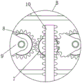
FIG. 1 is a cross-sectional view of an elevation structure of the present utility model;
FIG. 2 is an enlarged view of the structure of FIG. 1A according to the present utility model;
FIG. 3 is an enlarged view of the structure of FIG. 1B in accordance with the present utility model;
fig. 4 is a schematic top view of the present utility model.
In the figure: 1. a processing table; 2. a support frame; 3. a hydraulic cylinder; 4. a fixed frame; 5. a motor; 6. a push plate; 7. a transmission gear; 8. a first gear; 9. a sector gear; 10. a rack; 11. a mounting plate; 12. moon cake mould; 13. a threaded rod; 14. a connecting rod; 15. a slide block; 16. a guide rod; 17. and a limit groove.
Detailed Description
The following description of the embodiments of the present utility model will be made clearly and completely with reference to the accompanying drawings, in which it is apparent that the embodiments described are only some embodiments of the present utility model, but not all embodiments. All other embodiments, which can be made by those skilled in the art based on the embodiments of the utility model without making any inventive effort, are intended to be within the scope of the utility model.
Example 1
The embodiment aims to facilitate solving the problem that a punch is required to move downwards with a stamping die to stamp and shape a lower moon cake ball in the using process, but after the stamping die is used for stamping, the moon cake ball is easy to adhere to the inner wall of the stamping die after stamping due to dough generation, and is inconvenient to demolding, referring to fig. 1, 3 and 4, the moon cake stamping device comprises a processing table 1, wherein the upper end of the processing table 1 is fixedly connected with a supporting frame 2, and the upper end of the supporting frame 2 is provided with a hydraulic cylinder 3;
the fixed frame 4 of output fixedly connected with of pneumatic cylinder 3, motor 5 is installed to the outer wall of fixed frame 4, the output of motor 5 is through driving medium swing joint there being push pedal 6, the driving medium includes driving gear 7, driving gear 7's tip and motor 5's output fixed connection, driving gear 7's outer wall meshing is connected with first gear 8, first gear 8 is provided with two, two first gears 8 are axisymmetric setting about driving gear 7, two first gear 8's tip fixedly connected with sector gear 9, sector gear 9's outer wall meshing is connected with rack 10, rack 10's lower extreme fixedly connected with push pedal 6.
In this embodiment: when the moon cake pressing die device is used, firstly, moon cake balls are placed on the upper surface of a processing table 1, then a hydraulic cylinder 3 is started, the hydraulic cylinder 3 drives a fixing frame 4 below and a moon cake die 12 to move downwards, the moon cake balls are pressed downwards to perform pressing die in the downward moving process of the moon cake die 12, after pressing die, the hydraulic cylinder 3 is started to drive the moon cake die 12 to move upwards, at the moment, a motor 5 is started, the motor 5 drives a transmission gear 7 to rotate, the transmission gear 7 drives first gears 8 on two sides to rotate through a meshing relationship, a sector gear 9 is driven to rotate when the first gears 8 rotate, the sector gear 9 drives a rack 10 to move downwards through the meshing relationship, and the rack 10 drives a push plate 6 to push the moon cake balls after pressing die downwards to perform demolding, so that the moon cake balls are separated from the moon cake die 12.
Example 2
The embodiment aims to facilitate the butt joint connection of the traditional stamping die and the stamping head by adopting a plurality of bolts, the connection mode is relatively firm, but the disassembly is relatively inconvenient, the embodiment is an improvement on the basis of the embodiment 1, specifically, please refer to fig. 1, fig. 2 and fig. 4, the lower end of the fixed frame 4 is fixedly connected with the mounting plate 11, the mounting plate 11 is movably connected with the moon cake die 12 through a connecting piece, the connecting piece comprises a threaded rod 13, the inner contour of the mounting plate 11 is matched with the outer contour of the moon cake die 12, the threaded rod 13 is in threaded connection with the mounting plate 11, the end part of the threaded rod 13 is rotationally connected with a connecting rod 14, the connecting rod 14 is provided with two, the end part of the connecting rod 14 is rotationally connected with a sliding block 15, the inner wall of the sliding block 15 is slidably connected with a guide rod 16, the two ends of the guide rod 16 are fixedly connected with the inner wall of the mounting plate 11, the sliding block 15 is provided with two limiting grooves 17 are formed in the outer wall of the moon cake die 12, the inner contour of the limiting groove 17 is matched with the outer contour of the sliding block 15.
In this embodiment: when the moon cake die device is used, when the moon cake die 12 needs to be replaced, the threaded rod 13 is rotated at first, the threaded rod 13 moves upwards in the mounting plate 11 through a threaded connection relationship when rotating, the connecting rod 14 with the end in the upwards moving process deflects, the slide block 15 with the end in the connecting rod 14 deflecting process moves on the guide rod 16, and the slide block 15 gradually breaks away from the limiting groove 17 in the moving process, so that the moon cake die 12 can be removed.
It is noted that relational terms such as first and second, and the like are used solely to distinguish one entity or action from another entity or action without necessarily requiring or implying any actual such relationship or order between such entities or actions. Moreover, the terms "comprises," "comprising," or any other variation thereof, are intended to cover a non-exclusive inclusion, such that a process, method, article, or apparatus that comprises a list of elements does not include only those elements but may include other elements not expressly listed or inherent to such process, method, article, or apparatus.
The foregoing is merely a preferred embodiment of the present utility model, and it should be noted that it will be apparent to those skilled in the art that several modifications and variations can be made without departing from the technical principle of the present utility model, and these modifications and variations should also be regarded as the scope of the utility model.
Claims (8)
1. The moon cake die assembly comprises a processing table (1), and is characterized in that: the upper end of the processing table (1) is fixedly connected with a support frame (2), and a hydraulic cylinder (3) is arranged at the upper end of the support frame (2);
the output fixedly connected with fixed frame (4) of pneumatic cylinder (3), motor (5) are installed to the outer wall of fixed frame (4), the output of motor (5) is through driving medium swing joint has push pedal (6), the driving medium includes drive gear (7), the tip and the output fixed connection of motor (5) of drive gear (7), the outer wall meshing of drive gear (7) is connected with first gear (8).
2. A moon cake die assembly according to claim 1, wherein: the two first gears (8) are arranged, and the two first gears (8) are arranged in an axisymmetric mode relative to the transmission gear (7).
3. A moon cake die assembly according to claim 2, wherein: the end parts of the two first gears (8) are fixedly connected with sector gears (9), the outer walls of the sector gears (9) are connected with racks (10) in a meshed mode, and the lower ends of the racks (10) are fixedly connected with pushing plates (6).
4. A moon cake die assembly according to claim 1, wherein: the lower extreme fixedly connected with mounting panel (11) of fixed frame (4), mounting panel (11) are through connecting piece swing joint moon cake mould (12).
5. The moon cake die assembly as defined in claim 4, wherein: the connecting piece comprises a threaded rod (13), the inner outline of the mounting plate (11) is matched with the outer outline of the moon cake mould (12), and the threaded rod (13) is in threaded connection with the mounting plate (11).
6. The moon cake die assembly according to claim 5, wherein: the end part of the threaded rod (13) is rotatably connected with two connecting rods (14), and the end part of each connecting rod (14) is rotatably connected with a sliding block (15).
7. The moon cake die assembly as defined in claim 6, wherein: the inner wall sliding connection of slider (15) has guide bar (16), the both ends of guide bar (16) and the inner wall fixed connection of mounting panel (11).
8. The moon cake die assembly as defined in claim 7, wherein: the two sliding blocks (15) are arranged, limiting grooves (17) are formed in the outer wall of the moon cake die (12), and the inner contour of each limiting groove (17) is matched with the outer contour of the sliding block (15).
Priority Applications (1)
| Application Number | Priority Date | Filing Date | Title |
|---|---|---|---|
| CN202223266492.8U CN218999397U (en) | 2022-12-07 | 2022-12-07 | Moon cake die assembly |
Applications Claiming Priority (1)
| Application Number | Priority Date | Filing Date | Title |
|---|---|---|---|
| CN202223266492.8U CN218999397U (en) | 2022-12-07 | 2022-12-07 | Moon cake die assembly |
Publications (1)
| Publication Number | Publication Date |
|---|---|
| CN218999397U true CN218999397U (en) | 2023-05-12 |
Family
ID=86245192
Family Applications (1)
| Application Number | Title | Priority Date | Filing Date |
|---|---|---|---|
| CN202223266492.8U Active CN218999397U (en) | 2022-12-07 | 2022-12-07 | Moon cake die assembly |
Country Status (1)
| Country | Link |
|---|---|
| CN (1) | CN218999397U (en) |
-
2022
- 2022-12-07 CN CN202223266492.8U patent/CN218999397U/en active Active
Similar Documents
| Publication | Publication Date | Title |
|---|---|---|
| CN212664687U (en) | Stamping die based on demoulding component | |
| CN215657507U (en) | Stripping template for metal stamping die | |
| CN218999397U (en) | Moon cake die assembly | |
| CN214156023U (en) | Moon cake automatic forming machine | |
| CN113399581A (en) | Cold extrusion molding device for gear manufacturing | |
| CN220658829U (en) | Bending forming die | |
| CN220329698U (en) | Stamping device is used in stainless steel mould processing | |
| CN220129284U (en) | Demoulding mechanism based on full-automatic forming machine | |
| CN220837559U (en) | Stamping die convenient to drawing of patterns | |
| CN218925858U (en) | Press and mould for precisely forming petroleum drilling and production joint thereof | |
| CN220278119U (en) | Hardware stamping die convenient to drawing of patterns | |
| CN219378764U (en) | Mechanical shell mould convenient to model drawing of patterns | |
| CN218700981U (en) | Plastic cup forming die convenient to get piece | |
| CN215320397U (en) | Take back-off to form energy-saving injection mold of demoulding structure | |
| CN220127387U (en) | Stamping die for lamp housing manufacturing | |
| CN214488534U (en) | Easily ejecting motormeter dish stamping die | |
| CN218252474U (en) | Die device convenient to aluminium stamping workpiece drawing of patterns | |
| CN220698080U (en) | Stamping die convenient to adjust | |
| CN216938019U (en) | Automotive metal part forming and stamping die | |
| CN219130590U (en) | Stamping equipment is used in automobile parts production | |
| CN219838126U (en) | Quick demoulding mould | |
| CN217777904U (en) | Precise mold demolding device | |
| CN218109239U (en) | Forging processing equipment for producing precise die | |
| CN215849875U (en) | Ginseng branch plastic mould | |
| CN219820054U (en) | Ceramic molding press convenient for taking materials |
Legal Events
| Date | Code | Title | Description |
|---|---|---|---|
| GR01 | Patent grant | ||
| GR01 | Patent grant |