CN218252474U - Die device convenient to aluminium stamping workpiece drawing of patterns - Google Patents
Die device convenient to aluminium stamping workpiece drawing of patterns Download PDFInfo
- Publication number
- CN218252474U CN218252474U CN202221822871.8U CN202221822871U CN218252474U CN 218252474 U CN218252474 U CN 218252474U CN 202221822871 U CN202221822871 U CN 202221822871U CN 218252474 U CN218252474 U CN 218252474U
- Authority
- CN
- China
- Prior art keywords
- fixed
- die
- plate
- bottom plate
- aluminum
- Prior art date
- Legal status (The legal status is an assumption and is not a legal conclusion. Google has not performed a legal analysis and makes no representation as to the accuracy of the status listed.)
- Active
Links
Images


Abstract
The utility model relates to a die set convenient to aluminium stamping workpiece drawing of patterns, comprising a base plate, the top of bottom plate is equipped with the demoulding mechanism who is used for quick drawing of patterns to aluminium stamping workpiece, the top of bottom plate is equipped with quantity and is no less than two thimbles, the top of bottom plate is equipped with the bed die, the top of bed die is equipped with the mould, the last perpendicular surface of bottom plate is fixed with two risers, demoulding mechanism comprises push-down subassembly and ejecting subassembly, and wherein push-down subassembly is including fixing the left motor at left side riser, the output shaft of motor runs through the left side of left side riser and extends to the right side of left side riser and is fixed with the bull stick. According to the die device convenient for demolding of the aluminum stamping parts, the output shafts of the two electric push rods drive the two connecting plates to move towards the opposite side direction, the two moving plates are located below the movable plate, the movable plate starts to be driven to move upwards by the aid of the connecting plates, the aluminum stamping parts are demolded by the aid of the ejector pins, and accordingly the purpose of rapid demolding is achieved.
Description
Technical Field
The utility model relates to the technical field of dies, specifically be a die set convenient to aluminium stamping workpiece drawing of patterns.
Background
The die is various dies and tools for obtaining required products by injection molding, blow molding, extrusion, die casting or forging molding, smelting, stamping and the like in industrial production, particularly the stamping die is a special process device for processing materials into parts in cold stamping processing, which is called as a cold stamping die, stamping is a pressure processing method for obtaining required parts by applying pressure to the materials by using the die arranged on a press machine at room temperature to separate or plastically deform the materials, and after a workpiece is subjected to stamping forming, the workpiece is taken out from the die.
Traditional aluminium stamping workpiece mould is in the use, need put the aluminium stamping workpiece in the bed die, utilizes the mould of installing on the press to exert pressure to the aluminium stamping workpiece, makes the aluminium stamping workpiece produce separation or plastic deformation, and after the aluminium stamping workpiece formed in last mould and bed die, can not carry out the fast demoulding, and the operation is more complicated, has reduced the efficiency of aluminium stamping workpiece drawing of patterns, consequently provides a mould device convenient to aluminium stamping workpiece drawing of patterns.
SUMMERY OF THE UTILITY MODEL
Not enough to prior art, the utility model provides a die set convenient to aluminium stamping workpiece drawing of patterns possesses the advantage of quick drawing of patterns, has solved when aluminium stamping workpiece shaping back in die cavity and core, can not carry out the problem of quick drawing of patterns.
In order to achieve the above object, the utility model provides a following technical scheme: a die device convenient for demolding an aluminum stamping part comprises a bottom plate, wherein a demolding mechanism used for rapidly demolding the aluminum stamping part is arranged above the bottom plate, at least two ejector pins are arranged above the bottom plate, a lower die is arranged above the bottom plate, an upper die is arranged above the lower die, and two vertical plates are vertically fixed on the upper surface of the bottom plate;
the demolding mechanism comprises a pressing component and an ejection component, wherein the pressing component comprises a motor fixed on the left side of a left vertical plate, an output shaft of the motor penetrates through the left side of the left vertical plate, extends to the right side of the left vertical plate and is fixedly provided with a rotating rod, two first gears are fixed on the outer side of the rotating rod, second gears are meshed with the outer sides of the two first gears, screw rods are fixed inside the two second gears, the outer sides of the two screw rods are in threaded connection with movable sleeves, and a movable plate is fixed at the bottom ends of the two movable sleeves;
the ejection assembly comprises two fixed plates which are vertically fixed on the lower surface of the movable plate, one side, opposite to the fixed plates, of each fixed plate is fixedly provided with an electric push rod, the outer side of an output shaft of each electric push rod is fixedly provided with a connecting plate, the upper surface of the bottom plate is vertically fixedly provided with two slide rods, the top ends of the slide rods are fixedly provided with a baffle, the top ends of the slide rods are fixedly provided with a spring, the lower surface of the baffle is fixedly provided with a movable plate, the lower surface of the lower die is communicated with waste pipes, the waste pipes are not less than two in quantity, and a material receiving box is fixedly arranged below the upper surface of the bottom plate and located on the lower die.
Furthermore, the upper surface of bottom plate is fixed with four support columns two perpendicularly the upper surface of riser is fixed with the roof, the top at four support columns is fixed to the bed die.
Furthermore, the quantity is no less than two the equal vertical fixation of thimble is on the upper surface of fly leaf, two the spring suit is in the outside of two slide bars respectively.
Furthermore, the upper surface of the movable plate is provided with a slide hole in sliding connection with the two slide bars, and one side, opposite to the two connecting plates, is provided with a groove matched with the diameters of the two slide bars respectively.
Further, the below level of bull stick is equipped with the mounting panel, two the screw rod all passes through the inside of bearing vertical rotation connection at the mounting panel.
Furthermore, two chutes are respectively formed in the opposite sides of the two vertical plates, and sliding blocks connected with the chutes are respectively fixed to the left side and the right side of the moving plate.
Further, the upper die is fixed on the lower surface of the moving plate and close to the center of the moving plate, and a hole groove in clearance fit with the ejector pin is formed in the lower surface of the lower die.
Compared with the prior art, the technical scheme of the application has the following beneficial effects:
1. this die set convenient to aluminium stamping workpiece drawing of patterns through driving motor, because two movable sleeves all fix the upper surface at the movable plate, and the movable plate passes through the sliding connection between the slider of the left and right sides and the spout, fixes a position two movable sleeves, consequently two movable sleeves horizontal downstream, utilize the mould to exert pressure to the aluminium stamping workpiece, make the aluminium stamping workpiece produce separation or plastic deformation.
2. This die set convenient to aluminium stamping workpiece drawing of patterns drives two connecting plates respectively through two electric putter's output shaft and moves to relative one side direction, makes two movable plates be located the below of fly leaf, utilizes the connecting plate to begin to drive the fly leaf rebound, utilizes the thimble to carry out drawing of patterns work with the aluminium stamping workpiece, reaches the purpose of quick drawing of patterns.
Drawings
FIG. 1 is a schematic view of the present invention;
fig. 2 is a schematic view of the demolding mechanism of the present invention;
fig. 3 is a schematic view of the demolding mechanism of the present invention.
In the figure: 1, 2, a demoulding mechanism, 201 motors, 202 rotating rods, 203 first gears, 204 second gears, 205 screws, 206 movable sleeves, 207 moving plates, 208 fixed plates, 209 electric push rods, 210 connecting plates, 211 sliding rods, 212 springs, 213 baffles, 214 moving plates, 215 waste pipes, 216 waste bins, 3 top plates, 4 risers, 5 support columns, 6 ejector pins, 7 upper moulds and 8 lower moulds.
Detailed Description
The technical solutions in the embodiments of the present invention will be described clearly and completely with reference to the accompanying drawings in the embodiments of the present invention, and it is obvious that the described embodiments are only some embodiments of the present invention, not all embodiments. Based on the embodiments in the present invention, all other embodiments obtained by a person skilled in the art without creative work belong to the protection scope of the present invention.
Please refer to fig. 1, a die device convenient for demolding aluminum stamped parts in this embodiment, including a bottom plate 1, a demolding mechanism 2 for rapidly demolding the aluminum stamped parts is disposed above the bottom plate 1, ejector pins 6 with a number not less than two are disposed above the bottom plate 1, a lower die 8 is disposed above the bottom plate 1, waste ports with a number not less than two, which are specially used for transmitting waste materials after the aluminum stamped parts are disposed on the upper surface of the lower die 8, the waste ports with a number not less than two are respectively communicated with waste pipes 215 with a number not less than two, an upper die 7 is disposed above the lower die 8, the upper die 7 is utilized to apply pressure to the aluminum stamped parts, so that the aluminum stamped parts are separated or plastically deformed, and two vertical plates 4 are vertically fixed on the upper surface of the bottom plate 1.
The upper surface of bottom plate 1 vertical fixation has the upper surface of two risers 4 of four support columns 5 to be fixed with roof 3, and bed die 8 is fixed on the top of four support columns 5, plays the effect of support to bed die 8, and the lower surface of bed die 8 has been seted up with 6 clearance fit's of thimble hole grooves, and 6 passes the hole grooves and demolds the aluminium stamping workpiece.
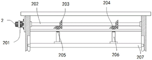
Referring to fig. 2, in order to separate or plastically deform the aluminum stamping part, the demolding mechanism 2 in this embodiment includes a pressing component and an ejecting component, where the pressing component includes a motor 201 fixed on the left side of the left-side vertical plate 4, an output shaft of the motor 201 penetrates through the left side of the left-side vertical plate 4 and extends to the right side of the left-side vertical plate 4, and is fixed with a rotating rod 202, the motor 201 is driven, at this time, the output shaft of the motor 201 starts to drive the rotating rod 202 to rotate, the rotating rod 202 drives two first gears 203 fixed on the outer sides of the rotating rod 202 to start rotating, so that two second gears 204 respectively engaged with the lower surfaces of the two first gears 203 start rotating, at this time, the rotating directions of the two second gears 204 are the same, two first gears 203 are fixed on the outer sides of the rotating rod 202, the outer sides of the two first gears 203 are both engaged with the second gears 204, both second gears 204 are fixed with screws 205 inside the two second gears 204, both outer sides of the two screws 205 are connected with movable sleeves 206 through threads, and when the processed aluminum stamping part needs to be demolded, the aluminum stamping part, the two movable sleeves 206 horizontally move downward to drive the movable plates 207 and move in the direction of the upper mold 7 and the bottom end of the movable plate 206.
In this example, a mounting plate is horizontally arranged below the rotating rod 202, the two screws 205 are vertically and rotatably connected inside the mounting plate through bearings, the two screws 205 are positioned through the mounting plate, two sliding grooves are respectively formed in one sides, opposite to the two vertical plates 4, of the two vertical plates, sliding blocks connected with the sliding grooves are respectively fixed to the left side and the right side of the moving plate 207, the two movable sleeves 206 are fixed to the upper surface of the moving plate 207, the moving plate 207 is positioned through sliding connection between the sliding blocks and the sliding grooves on the left side and the right side, the two movable sleeves 206 are horizontally moved downwards together, and the upper mold 7 is fixed to the lower surface of the moving plate 207 and is close to the center of the moving plate 207.
It should be noted that, by driving the motor 201, because the two movable sleeves 206 are both fixed on the upper surface of the moving plate 207, and the moving plate 207 positions the two movable sleeves 206 through the sliding connection between the sliding blocks and the sliding grooves on the left and right sides, the two movable sleeves 206 horizontally move downward, and the upper die 7 is used to apply pressure to the aluminum stamping part, so that the aluminum stamping part is separated or plastically deformed.
Referring to fig. 3, for the purpose of rapid demolding, the ejection assembly in this embodiment includes two fixing plates 208 vertically fixed on the lower surface of the moving plate 207, the fixing plates 208 on the left and right sides respectively drive the two electric push rods 209 to move downward, at this time, the two electric push rods 209 are activated, the output shafts of the two electric push rods 209 respectively drive the two connecting plates 210 to move toward opposite sides, so that the two connecting plates 210 are located below the moving plate 214, the electric push rods 209 are fixed on opposite sides of the two fixing plates 208, the connecting plates 210 are fixed on outer sides of the output shafts of the two electric push rods 209, two sliding rods 211 are vertically fixed on the upper surface of the bottom plate 1, the top ends of the two sliding rods 211 are fixed with baffles 213, the lower surfaces of the two baffles 213 are fixed with springs 212, the lower surfaces of the two springs 212 are fixed with the moving plate 214, the lower surface of the lower mold 8 is communicated with at least two scrap pipes 215, the scrap pipes 215 are located on opposite sides of two adjacent ejector pins 6, the bottom ends of the two scrap pipes 215 penetrate through the upper surface of the moving plate 214 and are slidably connected to the inside pipe grooves formed on the upper surface of the moving plate 214, when the moving plate 214 moves upward, the scrap pipes 215 do not contact with the bottom plate, the bottom plate 1, the scrap collecting box 216 is located on the rectangular upper surface of the rectangular collecting box, and the rectangular scrap collecting box 216, and the upper surface of the scrap collecting box is not less than the two scrap pipes 216, and the scrap collecting box is not less than the two scrap pipes 216.
In this example, the number of the two ejector pins 6 is not less than two, and the two ejector pins 6 are all vertically fixed on the upper surface of the movable plate 214, when the output shaft of the motor 201 rotates reversely, the movable plate 207 moves upwards, at this time, the connecting plate 210 starts to drive the movable plate 214 to move upwards, the left and right springs 212 start to compress, the ejector pins 6 are used for performing demolding work on the aluminum stamping part, the two springs 212 are respectively sleeved on the outer sides of the two sliding rods 211, the upper surface of the movable plate 214 is provided with sliding holes in sliding connection with the two sliding rods 211, one side of the two connecting plates 210 opposite to each other is respectively provided with grooves matched with the diameters of the two sliding rods 211, after the aluminum stamping part is ejected, the left and right electric push rods 209 respectively move the left and right connecting plates 210 to the opposite side, at this time, the left and right springs 212 start to reset, and the demolding work is convenient for the next time.
It should be noted that the output shafts of the two electric push rods 209 respectively drive the two connecting plates 210 to move towards opposite sides, so that the two connecting plates 210 are located below the movable plate 214, the connecting plates 210 start to drive the movable plate 214 to move upwards, and the ejector pins 6 are used to perform a demolding operation on the aluminum stamping part, thereby achieving the purpose of rapid demolding.
The working principle of the embodiment is as follows:
(1) When the aluminum stamping part needs to be stamped, the aluminum stamping part is placed in the lower die 8 positioned below, the motor 201 is driven, at this time, the output shaft of the motor 201 starts to drive the rotating rod 202 to rotate, the rotating rod 202 drives the two first gears 203 fixed on the outer sides of the rotating rod 202 to start rotating, so that the two second gears 204 respectively engaged with the lower surfaces of the two first gears 203 start rotating, at this time, the rotating directions of the two second gears 204 are the same, and the two screws 205 are respectively driven to start rotating, because the two movable sleeves 206 are fixed on the upper surface of the moving plate 207, and the moving plate 207 positions the two movable sleeves 206 through the sliding connection between the sliding blocks and the sliding grooves on the left side and the right side, so that the two movable sleeves 206 horizontally move downwards together, the aluminum stamping part is pressed by the upper die 7, so that the aluminum stamping part generates separation or plastic deformation, and meanwhile, the waste of the stamped aluminum stamping part enters the waste material of the waste material pipe 215 through the waste material opening and slides down to the waste material tank 216 along the waste material pipe 215, thereby achieving the purpose of automatically collecting the waste material.
(2) When the machined aluminum stamping part needs to be demolded, the two movable sleeves 206 horizontally move downwards to drive the moving plate 207 and the upper die 7 to move towards the lower die 8, at the moment, the left and right fixing plates 208 respectively drive the two electric push rods 209 to move downwards, at the moment, the two electric push rods 209 are started, output shafts of the two electric push rods 209 respectively drive the two connecting plates 210 to move towards one opposite side, so that the two connecting plates 210 are located below the moving plate 214, at the moment, the two slide rods 211 are respectively located in the two grooves, when the output shaft of the motor 201 rotates reversely, the moving plate 207 moves upwards, at the moment, the connecting plates 210 start to drive the moving plate 214 to move upwards, so that the left and right springs 212 start to compress, and at the same time, the ejector pins 6 are used for demolding operation of the aluminum stamping part, after the aluminum stamping part is ejected, the output shaft of the motor 201 is stopped, the left and right electric push rods 209 respectively move the left and right connecting plates 210 towards one opposite side, at the moment, the left and right springs 212 start the motor 201 to reset the upper die 7.
It should be noted that, in this document, relational terms such as first and second, and the like are used solely to distinguish one entity or action from another entity or action without necessarily requiring or implying any actual such relationship or order between such entities or actions. Also, the terms "comprises," "comprising," or any other variation thereof, are intended to cover a non-exclusive inclusion, such that a process, method, article, or apparatus that comprises a list of elements does not include only those elements but may include other elements not expressly listed or inherent to such process, method, article, or apparatus. Without further limitation, an element defined by the phrases "comprising a," "8230," "8230," or "comprising" does not exclude the presence of additional like elements in a process, method, article, or apparatus that comprises the element.
Although embodiments of the present invention have been shown and described, it will be appreciated by those skilled in the art that various changes, modifications, substitutions and alterations can be made in these embodiments without departing from the principles and spirit of the invention, the scope of which is defined in the appended claims and their equivalents.
Claims (7)
1. The utility model provides a die set convenient to aluminium stamping workpiece drawing of patterns, includes bottom plate (1), its characterized in that: a demolding mechanism (2) for rapidly demolding the aluminum stamping part is arranged above the bottom plate (1), at least two ejector pins (6) are arranged above the bottom plate (1), a lower mold (8) is arranged above the bottom plate (1), an upper mold (7) is arranged above the lower mold (8), and two vertical plates (4) are vertically fixed on the upper surface of the bottom plate (1);
the demolding mechanism (2) comprises a pressing component and an ejection component, wherein the pressing component comprises a motor (201) fixed on the left side of a left vertical plate (4), an output shaft of the motor (201) penetrates through the left side of the left vertical plate (4), extends to the right side of the left vertical plate (4) and is fixed with a rotating rod (202), two first gears (203) are fixed on the outer side of the rotating rod (202), second gears (204) are meshed on the outer sides of the two first gears (203), screw rods (205) are fixed inside the two second gears (204), movable sleeves (206) are connected on the outer sides of the two screw rods (205) in a threaded manner, and a movable plate (207) is fixed at the bottom ends of the two movable sleeves (206);
the ejection assembly comprises two fixing plates (208) which are vertically fixed on the lower surface of a moving plate (207), two electric push rods (209) are fixed on one opposite side of the fixing plate (208), two connecting plates (210) are fixed on the outer sides of output shafts of the electric push rods (209), two sliding rods (211) are vertically fixed on the upper surface of a bottom plate (1), two baffles (213) are fixed on the top ends of the sliding rods (211), two springs (212) are fixed on the lower surfaces of the baffles (213), two movable plates (214) are fixed on the lower surfaces of the springs (212), the lower surfaces of a lower die (8) are communicated with waste pipes (215) of which the number is not less than two, and a material receiving box (216) is fixed below the upper surface of the bottom plate (1) and located on the lower die (8).
2. The die assembly for facilitating die release of aluminum stampings of claim 1 wherein: the upper surface of bottom plate (1) is fixed with four support columns (5) two perpendicularly the upper surface of riser (4) is fixed with roof (3), the top at four support columns (5) is fixed in bed die (8).
3. The die assembly for facilitating die release of aluminum stampings of claim 1 wherein: the number of the thimbles (6) is not less than two, the thimbles are all vertically fixed on the upper surface of the movable plate (214), and the springs (212) are respectively sleeved on the outer sides of the two sliding rods (211).
4. The die assembly for facilitating the demolding of aluminum stamped parts according to claim 1, wherein: the upper surface of the movable plate (214) is provided with sliding holes in sliding connection with the two sliding rods (211), and one side, opposite to the two connecting plates (210), is provided with grooves matched with the diameters of the two sliding rods (211) respectively.
5. The die assembly for facilitating die release of aluminum stampings of claim 1 wherein: the lower level of bull stick (202) is equipped with the mounting panel, two screw rod (205) all rotate perpendicularly through the bearing and connect in the inside of mounting panel.
6. The die assembly for facilitating die release of aluminum stampings of claim 1 wherein: two sliding grooves are formed in one side, opposite to the vertical plates (4), of each vertical plate, and sliding blocks connected with the sliding grooves are fixed to the left side and the right side of the moving plate (207) respectively.
7. The die assembly for facilitating die release of aluminum stampings of claim 1 wherein: the upper die (7) is fixed on the lower surface of the moving plate (207) and is close to the center of the moving plate (207), and a hole groove in clearance fit with the ejector pin (6) is formed in the lower surface of the lower die (8).
Priority Applications (1)
| Application Number | Priority Date | Filing Date | Title |
|---|---|---|---|
| CN202221822871.8U CN218252474U (en) | 2022-07-15 | 2022-07-15 | Die device convenient to aluminium stamping workpiece drawing of patterns |
Applications Claiming Priority (1)
| Application Number | Priority Date | Filing Date | Title |
|---|---|---|---|
| CN202221822871.8U CN218252474U (en) | 2022-07-15 | 2022-07-15 | Die device convenient to aluminium stamping workpiece drawing of patterns |
Publications (1)
| Publication Number | Publication Date |
|---|---|
| CN218252474U true CN218252474U (en) | 2023-01-10 |
Family
ID=84762633
Family Applications (1)
| Application Number | Title | Priority Date | Filing Date |
|---|---|---|---|
| CN202221822871.8U Active CN218252474U (en) | 2022-07-15 | 2022-07-15 | Die device convenient to aluminium stamping workpiece drawing of patterns |
Country Status (1)
| Country | Link |
|---|---|
| CN (1) | CN218252474U (en) |
-
2022
- 2022-07-15 CN CN202221822871.8U patent/CN218252474U/en active Active
Similar Documents
| Publication | Publication Date | Title |
|---|---|---|
| CN111974857A (en) | Stamping discharging mechanism for automatic stamping equipment | |
| CN218252474U (en) | Die device convenient to aluminium stamping workpiece drawing of patterns | |
| CN219274261U (en) | Stamping device | |
| CN110202824B (en) | Die carrier mechanism for high-precision powder die-pressing forming servo press | |
| CN208527844U (en) | A kind of stamping die with Anti-blockage function | |
| CN216027704U (en) | Closed door type double-crankshaft precision punch with overload protection | |
| CN213033374U (en) | Limiting device for punch forming | |
| CN211727071U (en) | Novel elbow mould | |
| CN212976448U (en) | Stamping die for part machining | |
| CN212144210U (en) | Sub vehicle frame hypoplastron stamping die before car | |
| CN208728657U (en) | A kind of auto parts production mould suitable for high-speed production | |
| CN208341475U (en) | A kind of die assembly convenient for blanking | |
| CN207681323U (en) | A kind of Press Tools for Automobiles with automatic demoulding mechanism | |
| CN207872887U (en) | A kind of sports equipment bend pipe flattening mold for forming | |
| CN219357544U (en) | Metal die-casting forming stamping equipment of mechanical design | |
| CN220739301U (en) | Demoulding device for automobile hardware mould stamping parts | |
| CN220329698U (en) | Stamping device is used in stainless steel mould processing | |
| CN217550863U (en) | Mould with regulatory function | |
| CN215431257U (en) | Extrusion forming die | |
| CN211679623U (en) | Cold-pressing steel die | |
| CN213350484U (en) | Stamping die for metal plate | |
| CN219378764U (en) | Mechanical shell mould convenient to model drawing of patterns | |
| CN218429534U (en) | Mould convenient to drawing of patterns | |
| CN217990668U (en) | Stamping die of television shell | |
| CN218925858U (en) | Press and mould for precisely forming petroleum drilling and production joint thereof |
Legal Events
| Date | Code | Title | Description |
|---|---|---|---|
| GR01 | Patent grant | ||
| GR01 | Patent grant | ||
| PE01 | Entry into force of the registration of the contract for pledge of patent right |
Denomination of utility model: A mold device for easy demolding of aluminum stamping parts Effective date of registration: 20230821 Granted publication date: 20230110 Pledgee: Agricultural Bank of China Limited Taizhou Economic Development Zone sub branch Pledgor: ZHEJIANG TAIHONG WANLI TECHNOLOGY CO.,LTD. Registration number: Y2023330001781 |
|
| PE01 | Entry into force of the registration of the contract for pledge of patent right |