CN218983623U - PCB board laser marking board material conveyor - Google Patents
PCB board laser marking board material conveyor Download PDFInfo
- Publication number
- CN218983623U CN218983623U CN202223098940.8U CN202223098940U CN218983623U CN 218983623 U CN218983623 U CN 218983623U CN 202223098940 U CN202223098940 U CN 202223098940U CN 218983623 U CN218983623 U CN 218983623U
- Authority
- CN
- China
- Prior art keywords
- fixed
- track
- rail
- movable
- seat
- Prior art date
- Legal status (The legal status is an assumption and is not a legal conclusion. Google has not performed a legal analysis and makes no representation as to the accuracy of the status listed.)
- Active
Links
Images


Abstract
The utility model discloses a PCB laser marking board conveying device which comprises a fixed rail, a fixed seat, a movable rail, a sliding seat, a guide rail, a spacing adjusting mechanism, a first narrow-band conveying mechanism and a second narrow-band conveying mechanism, wherein the fixed rail is arranged on the fixed seat, the sliding seat is arranged on the guide rail, the movable rail is arranged on the sliding seat, the fixed rail and the movable rail are arranged in parallel, the spacing adjusting mechanism is arranged between the fixed seat and the sliding seat, the first narrow-band conveying mechanism is arranged on the fixed rail, and the second narrow-band conveying mechanism is arranged on the movable rail. According to the utility model, the boards subjected to laser marking of the PCB can be automatically conveyed to the lower part of the laser marking machine for laser marking operation, the distance between the fixed rail and the movable rail can be adjusted according to the boards processed according to actual needs, the board conveying of different sizes is satisfied, and the board conveying is ensured to be free from deflection.
Description
Technical Field
The utility model relates to the technical field of PCB processing, in particular to a PCB laser marking board conveying device.
Background
The laser marking is a marking method which uses high-energy density laser to locally irradiate a tool to enable surface layer materials to be gasified or to generate chemical reaction with color change, so that permanent marks are left, various character signs, patterns and the like can be marked by the laser marking, the laser marking has special significance for product anti-counterfeiting, the current PCB marking demands are more and more, and the following problems exist when the existing laser marking machine processes a circuit board:
(1) The existing conveying device is a necessary device for automatic line production, the common conveying device adopts more belt transmission, the width of the common conveying device cannot be adjusted, the common conveying device adopts fixed width, and the conveying devices with different widths are required to be replaced according to the size requirement of actually required conveyed products, so that the conveying device has certain limitation, is time-consuming and labor-consuming, and greatly reduces the working efficiency;
(2) The workpiece to be marked is required to be sent to the lower part of the marking head for marking, the workpiece is taken down after marking is finished, the workload of staff is large, the working efficiency is low, and mass production cannot be met.
Disclosure of Invention
The utility model aims to: aiming at the problems and the defects in the prior art, the utility model aims to provide a PCB laser marking board conveying device.
The technical scheme is as follows: in order to achieve the above purpose, the PCB laser marking board conveying device comprises a fixed rail, a fixed seat, a movable rail, a sliding seat, a sliding rail, a spacing adjusting mechanism, a first narrow-band conveying mechanism, a second narrow-band conveying mechanism and a PCB marking limiting device, wherein the fixed rail is arranged on the fixed seat, the sliding seat is arranged on the sliding rail, the movable rail is arranged on the sliding seat, the fixed rail and the movable rail are arranged in parallel, the spacing adjusting mechanism is arranged between the fixed seat and the sliding seat, the first narrow-band conveying mechanism is arranged on the fixed rail, the second narrow-band conveying mechanism is arranged on the movable rail, and the PCB marking limiting device is arranged between the fixed rail and the movable rail.
Further, the interval adjusting mechanism comprises an adjusting hand wheel, an adjusting screw rod I, an adjusting screw rod II and a synchronous belt pulley assembly, one end of the adjusting screw rod I penetrates through the fixed seat and then is connected with the adjusting hand wheel, the other end of the adjusting screw rod I is connected with the sliding seat, and the other end of the adjusting screw rod I penetrates out of the sliding seat and then is connected with the synchronous belt pulley assembly; and two ends of the second adjusting screw rod are respectively connected with the fixed seat and the sliding seat.
Further, the synchronous pulley assembly comprises a first supporting seat, a second supporting seat, a first synchronous pulley, a second synchronous pulley and a synchronous belt, wherein the first supporting seat and the second supporting seat are arranged opposite to the sliding seat, the free end of the first adjusting screw rod is inserted into the first supporting seat, the free end of the second adjusting screw rod is inserted into the second supporting seat, the first synchronous pulley is arranged on the first adjusting screw rod, the second synchronous pulley is arranged on the second adjusting screw rod, and the first synchronous pulley and the second synchronous pulley are driven through the synchronous belt.
Further, the first narrow-band conveying mechanism and the second narrow-band conveying mechanism are identical in structure and comprise conveying motors, track belts, driving wheels, driven wheels and tensioning wheels, the conveying motors are arranged on the outer sides of the fixed tracks and the movable tracks, the driving wheels and the driven wheels are arranged on the inner sides of the fixed tracks and the inner sides of the movable tracks, the tensioning wheels are arranged on the two sides of the driving wheels, an output shaft of the conveying motors is connected with the driving wheels, rubber rings are arranged on the driving wheels, and the track belts are arranged on the outer sides of the driving wheels and the outer sides of the driven wheels. The conveying motor is started, the driving wheel rotates, the friction force is utilized to drive the track belt to rotate, the driven wheel synchronously rotates under the action of the track belt, and the track belt stably conveys the PCB circuit board in the X-axis direction in the synchronous transmission process of the driving wheel and the driven wheel.
Further, PCB board marking stop device includes that the incoming material blocks subassembly, side clamp fixed subassembly, jacking structure and limit stop, the incoming material blocks the subassembly setting in fixed track's inboard, and the side clamp fixed subassembly sets up on the movable track, and jacking structure sets up between fixed track and movable track, and limit stop sets up respectively on fixed track and movable track. The feeding component blocks and positions the PCB conveyed by the first narrow-band conveying mechanism and the second narrow-band conveying mechanism, and the X-axis direction is limited at the moment; then the jacking structure and the limit stop realize limiting the PCB in the Z-axis direction; and the rearmost clamping and fixing assembly clamps the side surface of the jacked PCB.
Further, the incoming material blocking component comprises a blocking air cylinder and an L-shaped stop block, and a telescopic rod of the blocking air cylinder is connected with the L-shaped stop block. The telescopic link that blocks the cylinder rises, and L type dog is lifted, and L type dog stops the location with the PCB board this moment.
Further, the side clamp fixing assembly comprises a first linear slide rail, a side clamp stretching mechanism and a clamping jaw stop block, wherein the first linear slide rail is fixedly arranged on the outer side of the movable rail, the side clamp stretching mechanism is arranged on the outer side of the movable rail and is positioned between the first two linear slide rails, the clamping jaw stop block is arranged on the first linear slide rail in a sliding manner, and the side clamp stretching mechanism is connected with the bottom of the clamping jaw stop block; the side clamp stretching mechanism comprises a stretching cylinder, a cylinder connecting piece and a constant-height screw, wherein the stretching cylinder is fixedly arranged on the outer side of the movable rail, a telescopic rod of the stretching cylinder is connected with the cylinder connecting piece, and the constant-height screw penetrates through a through hole of the cylinder connecting piece and then is connected to the clamping jaw stop block.
The stretching cylinder drives the cylinder connecting piece to move, the cylinder connecting piece drives the clamping jaw stop block to do linear motion along the first linear sliding rail, the motion direction of the stretching cylinder is consistent with that of the clamping jaw stop block, after the PCB is jacked up and limited by the jacking structure, the telescopic rod of the stretching cylinder is retracted, the clamping jaw stop block is controlled to limit and clamp the side edge of the PCB, and after laser coding is finished, the telescopic rod of the stretching cylinder extends out, and the clamping jaw stop block returns to the original position; the buffer spring plays a role in buffering when clamping the PCB.
Further, the jacking structure comprises a jacking mechanism and a jacking sheet metal component, the jacking mechanism is arranged between the fixed rail and the movable rail, and the jacking sheet metal component is respectively arranged on the fixed rail and the movable rail. The lifting mechanism pushes the ejection sheet metal component to move upwards, the PCB in the conveying process is lifted from the bottom, and the limit stop limits the PCB from the upper part, so that the limitation of the Z-axis direction is realized.
Further, the jacking mechanism comprises a jacking cylinder, a supporting plate and a telescopic guide column, wherein the jacking cylinder is arranged at the bottom of the middle position of the supporting plate, a telescopic rod of the cylinder jacking cylinder is connected with the bottom of the supporting plate, and the telescopic guide column is arranged below four corners of the supporting plate; buffer cylinders are further arranged at four corners of the lower side of the supporting plate.
Further, the liftout sheet metal component includes linear guide rail two, sliding support seat, supporting shoe, bolt post and jacking sheet metal component, linear guide rail two sets up in fixed track and the orbital outside of activity regulation, and sliding support seat sets up in linear guide rail two's outside, sliding support seat's bottom sets up the supporting shoe, the supporting shoe joint is in fixed track and the orbital downside of activity, and the bolt post sets up the downside at the supporting shoe, and the jacking sheet metal component sets up the upside at the supporting shoe.
The technical scheme can be seen that the beneficial effects of the utility model are as follows:
(1) The PCB laser marking board conveying device can realize automatic conveying of boards subjected to PCB laser marking, the distance between the fixed rail and the movable rail can be adjusted according to boards processed according to actual needs, conveying of boards with different sizes is met, and no deflection of board conveying can be guaranteed.
(2) According to the PCB laser marking board conveying device, incoming material blocking can be achieved in the conveying process of the PCB, the PCB is jacked up, meanwhile, the side clamps and the height are limited, the limited PCB is subjected to laser head to achieve accurate marking operation, and the situation that the PCB is deviated or slipped off is avoided; after marking, the incoming material blocking assembly, the side clamping fixing assembly and the jacking structure reset to place the PCB on the conveying track again, the PCB after marking is continuously conveyed out, the PCB is not required to be taken and placed, the workload of workers is reduced, and the working efficiency is improved.
Drawings
FIG. 1 is a schematic diagram of the structure of the present utility model;
FIG. 2 is a top view of FIG. 1;
FIG. 3 is a schematic view of a side clamp assembly according to the present utility model;
FIG. 4 is a schematic structural view of a jacking structure according to the present utility model;
FIG. 5 is a top view of FIG. 4;
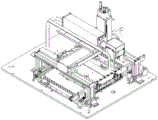
fig. 6 is a schematic view of the structure of the board conveying device mounted on the laser marking machine.
Detailed Description
The utility model is further elucidated below in connection with the drawings and the specific embodiments.
The PCB laser marking plate conveying device comprises a fixed rail 1, a fixed seat 2, a movable rail 3, a sliding seat 4, a sliding rail 5, a spacing adjusting mechanism 6, a first narrow-band conveying mechanism 7, a second narrow-band conveying mechanism 8 and a PCB marking limiting device 9, wherein the fixed rail 1 is arranged on the fixed seat 2, the sliding seat 4 is arranged on the sliding rail 5, the movable rail 3 is arranged on the sliding seat 4, the fixed rail 1 and the movable rail 3 are arranged in parallel, the spacing adjusting mechanism 6 is arranged between the fixed seat 2 and the sliding seat 4, the first narrow-band conveying mechanism 7 is arranged on the fixed rail 1, the second narrow-band conveying mechanism 8 is arranged on the movable rail 3, and the PCB marking limiting device 9 is arranged between the fixed rail 1 and the movable rail 3.
The space adjusting mechanism 6 comprises an adjusting hand wheel 61, an adjusting screw rod I62, an adjusting screw rod II 63 and a synchronous pulley assembly 64, wherein one end of the adjusting screw rod I62 penetrates through the fixed seat 2 and then is connected with the adjusting hand wheel 61, the other end of the adjusting screw rod I62 is connected with the sliding seat 4, and the other end of the adjusting screw rod I62 penetrates out of the sliding seat 4 and then is connected with the synchronous pulley assembly 64; two ends of the second adjusting screw 63 are respectively connected with the fixed seat 2 and the sliding seat 4.
In this embodiment, the synchronous pulley assembly 64 includes a first support base 641, a second support base 642, a first synchronous pulley 643, a second synchronous pulley 644 and a synchronous belt 645, the first support base 641 and the second support base 642 are disposed opposite to the sliding base 4, the free end of the first adjusting screw 62 is inserted in the first support base 641, the free end of the second adjusting screw 63 is inserted in the second support base 642, the first synchronous pulley 643 is mounted on the first adjusting screw 62, the second synchronous pulley 644 is mounted on the second adjusting screw 63, and the first synchronous pulley 643 and the second synchronous pulley 644 are driven by the synchronous belt 645.
In this embodiment, the first and second narrow- band conveying mechanisms 7 and 8 have the same structure and each include a conveying motor 71, a track belt 72, a driving wheel 73, a driven wheel 74 and a tensioning wheel 75, the conveying motor 71 is mounted on the outer sides of the fixed track 1 and the movable track 3, the driving wheel 73 and the driven wheel 74 are mounted on the inner sides of the fixed track 1 and the movable track 3, the tensioning wheels 75 are arranged on two sides of the driving wheel 73, an output shaft of the conveying motor 71 is connected with the driving wheel 73, a rubber ring is arranged on the driving wheel 73, and the track belt 72 is arranged on the outer sides of the driving wheel 73 and the driven wheel 74.
In this embodiment, the PCB board marking limiting device 9 includes a material blocking component 91, a side clamping fixing component 92, a jacking structure 93 and a limit stop 94, where the material blocking component 91 is disposed on the inner side of the fixed rail 1, the side clamping fixing component 92 is disposed on the movable rail 3, the jacking structure 93 is disposed between the fixed rail 1 and the movable rail 3, and the limit stop 94 is disposed on the fixed rail 1 and the movable rail 3 respectively.
The incoming material blocking assembly 91 in this embodiment includes a blocking cylinder 911 and an L-shaped block 912, and a telescopic rod of the blocking cylinder 911 is connected with the L-shaped block 912.
As shown in fig. 3, the side clamp fixing assembly 92 includes a first linear rail 921, a side clamp stretching mechanism 922 and a clamping jaw block 923, wherein the first linear rail 921 is fixedly installed on the outer side of the movable rail 3, the side clamp stretching mechanism 922 is arranged on the outer side of the movable rail 3 and between the two first linear rails 921, the clamping jaw block 923 is slidably arranged on the first linear rail 921, and the side clamp stretching mechanism 922 is connected with the bottom of the clamping jaw block 923; the side clamping stretching mechanism 922 comprises a stretching cylinder 9221, a cylinder connecting piece 9222 and a contour screw 9223, wherein the stretching cylinder 9221 is fixedly arranged on the outer side of the movable track 3, a telescopic rod of the stretching cylinder 9221 is connected with the cylinder connecting piece 9222, the contour screw 9223 penetrates through a through hole of the cylinder connecting piece 9222 and then is connected to the clamping jaw stop block 923, and a buffer spring 9224 is arranged on the outer side of the contour screw 9223.
As shown in fig. 4 and 5, the lifting structure 93 includes a lifting mechanism 931 and a sheet metal component 932, the lifting mechanism 931 is disposed between the fixed rail 1 and the movable rail 3, and the sheet metal component 932 is disposed on the fixed rail 1 and the movable rail 3.
The jacking mechanism 931 in this embodiment includes a jacking cylinder 9311, a support plate 9312 and a telescopic guide column 9313, the jacking cylinder 9311 is disposed at the bottom of the middle position of the support plate 9312, a telescopic rod of the jacking cylinder 9311 is connected to the bottom of the support plate 9312, and the telescopic guide column 9313 is disposed below the four corners of the support plate 9312; buffer cylinders are also provided at the four corners of the underside of the support plate 9312.
In this embodiment, the ejector metal plate assembly 932 includes a second linear guide 9321, a sliding support 9322, a support block 9323, a bolt column 9324 and a lifting metal plate 9325, where the second linear guide 9321 is disposed on the outer sides of the fixed rail 1 and the movable rail 3, the sliding support 9322 is disposed on the outer sides of the second linear guide 9321, the support block 9323 is disposed at the bottom of the sliding support 9322, the support block 9323 is clamped to the lower sides of the fixed rail 1 and the movable rail 3, the bolt column 9324 is disposed on the lower side of the support block 9323, and the lifting metal plate 9325 is vertically disposed on the upper side of the support block 9323.
As shown in fig. 6, the board conveying device is installed below the laser marking machine, after the PCB board is placed on the first narrowband conveying mechanism 7 and the second narrowband conveying mechanism 8, automatic conveying is achieved, the distance between the fixed rail 1 and the movable rail 3 can be adjusted according to boards processed according to actual needs, conveying of PCB boards with different sizes is met, no deflection of board conveying can be guaranteed, when the PCB board is conveyed to the position right below the laser marking machine, the incoming material blocking component 91 achieves incoming material blocking, and the side clamps and the height limit are achieved when the PCB board is jacked up, the limited PCB board achieves accurate marking operation through the laser marking machine, and the PCB board deviation or the PCB board slipping cannot occur; after marking, the incoming material blocking component 91, the side clamping fixing component 92 and the jacking structure 93 are reset, the PCB is replaced on the board conveying device, the printed circuit board after marking is continuously conveyed out, the PCB circuit board is not required to be taken and placed, the workload of workers is reduced, and the working efficiency is improved.
The examples are intended to illustrate the utility model and not to limit its scope, and after reading the utility model, various equivalents of the utility model by those skilled in the art are within the scope of the utility model as defined by the claims appended hereto.
Claims (10)
1. PCB board laser marking panel conveyor, its characterized in that: including fixed track (1), fixing base (2), movable rail (3), sliding seat (4), slide rail (5), interval adjustment mechanism (6), narrowband conveying mechanism one (7), narrowband conveying mechanism two (8) and PCB board mark stop device (9), fixed track (1) are installed on fixing base (2), and sliding seat (4) are installed on slide rail (5), and movable rail (3) are installed on sliding seat (4), and fixed track (1) and movable rail (3) parallel arrangement, be equipped with interval adjustment mechanism (6) between fixing base (2) and sliding seat (4), narrowband conveying mechanism one (7) set up on fixed track (1), narrowband conveying mechanism two (8) set up on movable rail (3), PCB board mark stop device (9) set up between fixed track (1) and movable rail (3).
2. The PCB board laser marking board material conveying device according to claim 1, wherein: the space adjusting mechanism (6) comprises an adjusting hand wheel (61), an adjusting screw rod I (62), an adjusting screw rod II (63) and a synchronous pulley assembly (64), one end of the adjusting screw rod I (62) penetrates through the fixed seat (2) and then is connected with the adjusting hand wheel (61), the other end of the adjusting screw rod I (62) is connected with the sliding seat (4), and the other end of the adjusting screw rod I (62) penetrates out of the sliding seat (4) and then is connected with the synchronous pulley assembly (64); two ends of the second adjusting screw rod (63) are respectively connected with the fixed seat (2) and the sliding seat (4).
3. The PCB board laser marking board material conveying apparatus according to claim 2, wherein: the synchronous pulley assembly (64) comprises a first supporting seat (641), a second supporting seat (642), a first synchronous pulley (643), a second synchronous pulley (644) and a synchronous belt (645), wherein the first supporting seat (641) and the second supporting seat (642) are arranged opposite to the sliding seat (4), the free end of the first adjusting screw (62) is inserted on the first supporting seat (641), the free end of the second adjusting screw (63) is inserted on the second supporting seat (642), the first synchronous pulley (643) is arranged on the first adjusting screw (62), the second synchronous pulley (644) is arranged on the second adjusting screw (63), and the first synchronous pulley (643) and the second synchronous pulley (644) are in transmission through the synchronous belt (645).
4. The PCB board laser marking board material conveying device according to claim 1, wherein: the narrow-band conveying mechanism I (7) and the narrow-band conveying mechanism II (8) are identical in structure and comprise a conveying motor (71), a track belt (72), a driving wheel (73), a driven wheel (74) and a tensioning wheel (75), the conveying motor (71) is arranged on the outer sides of a fixed track (1) and a movable track (3), the driving wheel (73) and the driven wheel (74) are arranged on the inner sides of the fixed track (1) and the movable track (3), the tensioning wheel (75) is arranged on the two sides of the driving wheel (73), an output shaft of the conveying motor (71) is connected with the driving wheel (73), a rubber ring is arranged on the driving wheel (73), and the track belt (72) is arranged on the outer sides of the driving wheel (73) and the driven wheel (74).
5. The PCB board laser marking board material conveying device according to claim 1, wherein: PCB board marking stop device (9) are including incoming material blocking subassembly (91), side clamp fixed subassembly (92), jacking structure (93) and limit stop (94), incoming material blocking subassembly (91) set up the inboard at fixed track (1), side clamp fixed subassembly (92) set up on movable track (3), jacking structure (93) set up between fixed track (1) and movable track (3), limit stop (94) set up respectively on fixed track (1) and movable track (3).
6. The PCB board laser marking board material conveying apparatus according to claim 5, wherein: the incoming material blocking assembly (91) comprises a blocking air cylinder (911) and an L-shaped stop block (912), and a telescopic rod of the blocking air cylinder (911) is connected with the L-shaped stop block (912).
7. The PCB board laser marking board material conveying apparatus of claim 6, wherein: the side clamp fixing assembly (92) comprises first linear slide rails (921), side clamp stretching mechanisms (922) and clamping jaw check blocks (923), the first linear slide rails (921) are fixedly arranged on the outer sides of the movable rails (3), the side clamp stretching mechanisms (922) are arranged on the outer sides of the movable rails (3) and located between the first two linear slide rails (921), the clamping jaw check blocks (923) are arranged on the first linear slide rails (921) in a sliding mode, and the side clamp stretching mechanisms (922) are connected with the bottoms of the clamping jaw check blocks (923); the side clamp stretching mechanism (922) comprises a stretching cylinder (9221), a cylinder connecting piece (9222) and a contour screw (9223), the stretching cylinder (9221) is fixedly arranged on the outer side of the movable track (3), a telescopic rod of the stretching cylinder (9221) is connected with the cylinder connecting piece (9222), the contour screw (9223) penetrates through a through hole of the cylinder connecting piece (9222) and then is connected to the clamping jaw stop block (923), and a buffer spring (9224) is arranged on the outer side of the contour screw (9223).
8. The PCB board laser marking board material conveying apparatus of claim 7, wherein: the jacking structure (93) comprises a jacking mechanism (931) and a jacking sheet metal component (932), the jacking mechanism (931) is arranged between the fixed rail (1) and the movable rail (3), and the jacking sheet metal component (932) is arranged on the fixed rail (1) and the movable rail (3).
9. The PCB board laser marking board material conveying apparatus of claim 8, wherein: the lifting mechanism (931) comprises a lifting cylinder (9311), a supporting plate (9312) and a telescopic guide column (9313), the lifting cylinder (9311) is arranged at the bottom of the middle position of the supporting plate (9312), a telescopic rod of the lifting cylinder (9311) is connected with the bottom of the supporting plate (9312), and the telescopic guide column (9313) is arranged below four corners of the supporting plate (9312); buffer cylinders are also arranged at the four corners of the lower side of the supporting plate (9312).
10. The PCB board laser marking board material conveying apparatus of claim 9, wherein: the utility model provides a liftout panel beating subassembly (932) includes linear guide second (9321), sliding support seat (9322), supporting shoe (9323), bolt post (9324) and jacking sheet metal component (9325), linear guide second (9321) sets up in the outside of fixed track (1) and movable track (3), sliding support seat (9322) set up in the outside of linear guide second (9321), the bottom of sliding support seat (9322) sets up supporting shoe (9323), supporting shoe (9323) joint is in the downside of fixed track (1) and movable track (3), and bolt post (9324) set up the downside at supporting shoe (9323), and jacking sheet metal component (9325) set up the upside at supporting shoe (9323) perpendicularly.
Priority Applications (1)
| Application Number | Priority Date | Filing Date | Title |
|---|---|---|---|
| CN202223098940.8U CN218983623U (en) | 2022-11-22 | 2022-11-22 | PCB board laser marking board material conveyor |
Applications Claiming Priority (1)
| Application Number | Priority Date | Filing Date | Title |
|---|---|---|---|
| CN202223098940.8U CN218983623U (en) | 2022-11-22 | 2022-11-22 | PCB board laser marking board material conveyor |
Publications (1)
| Publication Number | Publication Date |
|---|---|
| CN218983623U true CN218983623U (en) | 2023-05-09 |
Family
ID=86221378
Family Applications (1)
| Application Number | Title | Priority Date | Filing Date |
|---|---|---|---|
| CN202223098940.8U Active CN218983623U (en) | 2022-11-22 | 2022-11-22 | PCB board laser marking board material conveyor |
Country Status (1)
| Country | Link |
|---|---|
| CN (1) | CN218983623U (en) |
Cited By (2)
| Publication number | Priority date | Publication date | Assignee | Title |
|---|---|---|---|---|
| CN116352279A (en) * | 2023-05-31 | 2023-06-30 | 深圳市克洛诺斯科技有限公司 | PCB laser marking device |
| CN116689981A (en) * | 2023-07-11 | 2023-09-05 | 苏州光宝科技股份有限公司 | Circuit board clamping rail |
-
2022
- 2022-11-22 CN CN202223098940.8U patent/CN218983623U/en active Active
Cited By (3)
| Publication number | Priority date | Publication date | Assignee | Title |
|---|---|---|---|---|
| CN116352279A (en) * | 2023-05-31 | 2023-06-30 | 深圳市克洛诺斯科技有限公司 | PCB laser marking device |
| CN116352279B (en) * | 2023-05-31 | 2023-08-08 | 深圳市克洛诺斯科技有限公司 | PCB laser marking device |
| CN116689981A (en) * | 2023-07-11 | 2023-09-05 | 苏州光宝科技股份有限公司 | Circuit board clamping rail |
Similar Documents
| Publication | Publication Date | Title |
|---|---|---|
| CN218983623U (en) | PCB board laser marking board material conveyor | |
| TWI761706B (en) | Energy saving and environmental protection digital cutting plotter | |
| CN110340200B (en) | High-precision high-speed punch press | |
| CN112548320A (en) | Feeding, positioning and fixing device and method for laser cutting of plates | |
| CN106985221B (en) | Numerical control table top mechanism with multi-section feeding, powerful elliptic sucker and servo clamping hand | |
| CN111703862B (en) | Transmission upset conveyer | |
| CN212708586U (en) | Ink jet printer | |
| CN211075193U (en) | Ceramic tile assembly line printer | |
| CN219254537U (en) | Multi-station laser marking machine | |
| CN209869897U (en) | Chopping block branding equipment | |
| CN112091616A (en) | Door plate production system | |
| CN111391482A (en) | Printing machine with curve is from version function | |
| CN215393284U (en) | Automatic feeding mechanism for laser cutting machine | |
| CN114750239B (en) | Stamping die positioning method applied to FPC processing | |
| CN212765431U (en) | Plate engraving machine | |
| US10967628B2 (en) | Energy-saving environment-friendly digital lettering machine | |
| CN214490910U (en) | Plank perforating device | |
| CN112123915A (en) | Be applied to full-automatic film tearing machine of FPC board | |
| CN209880562U (en) | Width-adjustable feeding device with plate returning function | |
| CN111136159A (en) | Numerical control production line for punching automobile longitudinal beam flat plate | |
| CN220693402U (en) | Automatic positioning and calibrating device for circuit board | |
| CN219132575U (en) | Automatic visual identification cutting machine | |
| CN212765435U (en) | Automatic engraver workstation of business turn over material | |
| CN217496802U (en) | Transfer printing mark automatic feeding mechanism | |
| CN217499620U (en) | Automatic bag sheet feeding mechanism |
Legal Events
| Date | Code | Title | Description |
|---|---|---|---|
| GR01 | Patent grant | ||
| GR01 | Patent grant |