CN218982854U - Punching device for machining - Google Patents
Punching device for machining Download PDFInfo
- Publication number
- CN218982854U CN218982854U CN202223199198.XU CN202223199198U CN218982854U CN 218982854 U CN218982854 U CN 218982854U CN 202223199198 U CN202223199198 U CN 202223199198U CN 218982854 U CN218982854 U CN 218982854U
- Authority
- CN
- China
- Prior art keywords
- punching device
- fixedly connected
- organism
- motor
- punching
- Prior art date
- Legal status (The legal status is an assumption and is not a legal conclusion. Google has not performed a legal analysis and makes no representation as to the accuracy of the status listed.)
- Active
Links
Images


Classifications
-
- Y—GENERAL TAGGING OF NEW TECHNOLOGICAL DEVELOPMENTS; GENERAL TAGGING OF CROSS-SECTIONAL TECHNOLOGIES SPANNING OVER SEVERAL SECTIONS OF THE IPC; TECHNICAL SUBJECTS COVERED BY FORMER USPC CROSS-REFERENCE ART COLLECTIONS [XRACs] AND DIGESTS
- Y02—TECHNOLOGIES OR APPLICATIONS FOR MITIGATION OR ADAPTATION AGAINST CLIMATE CHANGE
- Y02P—CLIMATE CHANGE MITIGATION TECHNOLOGIES IN THE PRODUCTION OR PROCESSING OF GOODS
- Y02P70/00—Climate change mitigation technologies in the production process for final industrial or consumer products
- Y02P70/10—Greenhouse gas [GHG] capture, material saving, heat recovery or other energy efficient measures, e.g. motor control, characterised by manufacturing processes, e.g. for rolling metal or metal working
Abstract
The utility model relates to the technical field of food processing and discloses a punching device for processing, which comprises a supporting seat, wherein the top of the supporting seat is fixedly connected with an organism, the top of the organism is fixedly connected with a workbench, the inside of the workbench is provided with a clamping device, the bottom of the organism is provided with a waste collection box positioned at the inner side of the supporting seat, the top of the organism is provided with the punching device, the punching device comprises a motor, the output end of the motor is fixedly connected with a motor shaft, the punching device for processing has the advantages of being applicable to multi-model iron cans for punching, waste collection and the like, multiple groups of dies are adopted for adapting to iron cans of different models, the clamping device is used for clamping a lower die, so that the iron cans of multiple models can be punched, waste collection boxes are used for collecting waste, and the problem that the punching device for processing is not applicable to multi-model iron cans and does not have a waste collection function is solved.
Description
Technical Field
The utility model relates to the technical field of food processing, in particular to a punching device for processing.
Background
The punching machine is a mechanical device for punching by using a punching die to act on a material under the driving of a power mechanism after raw materials are installed, the punching machine can process sheets, punch, mould, emboss and the like to force metal to enter the die, in modern industrial production, the flat plate punching machine is used as key equipment for processing various flat plate holes by using a novel forming technology to process the holes, the precision is high, the positioning accuracy and the production period are short, the traditional device is replaced, and the working principle of the punching machine is that the punching die acts on the material under the driving of the power mechanism after the raw materials are installed on a working tool platform, so that the punching operation is completed.
When punching a hole to the iron ladle, will use punching device, food iron ladle production processing is with punching device just one of them, but current punching device is when punching a hole to the iron ladle, can't carry out artifical collection to the waste material on the punching device, and does not possess waste collection device and carries out automatic collection to the waste material for the waste material can't obtain timely collection, can lead to waste material accumulation on the punching device too much, influences the quality of punching device when punching a hole to the iron ladle, when punching a hole to the iron ladle of different models, change the time overlength that cut-out mould need consume, can not accord with people's expectation.
Disclosure of Invention
Aiming at the defects of the prior art, the utility model provides a punching device for processing, which has the advantages of being applicable to punching of iron cans with multiple types and waste collection.
In order to achieve the above purpose, the present utility model provides the following technical solutions: the utility model provides a punching device is used in processing, includes the supporting seat, the top fixedly connected with organism of supporting seat, the top fixedly connected with workstation of organism, the inside of workstation is provided with clamping device, the bottom of organism is located the inboard of supporting seat and is provided with waste collection box, punching device is installed at the top of organism.
Preferably, the punching device comprises a motor, the output end of the motor is fixedly connected with a motor shaft, the bottom of the motor shaft is fixedly connected with a rotary table, and the bottom of the rotary table is provided with an upper die.
Preferably, the clamping device comprises a forward and reverse rotating motor, the output end of the forward and reverse rotating motor is fixedly connected with a driving shaft, the inside of the workbench is positioned on the right side of the driving shaft and is fixedly connected with a sliding rod, a clamp is arranged on the outside of the driving shaft and is fixedly connected with a rubber pad, a supporting table is arranged in the workbench, a waste outlet is arranged at the bottom of the supporting table in the workbench, and a lower die is arranged at the top of the supporting table.
Preferably, the two supporting seats are arranged, the length of the waste collection box is smaller than the shortest distance between the two supporting seats, the width of the waste collection box is smaller than the width of the supporting seats, the height of the waste collection box is smaller than the height of the supporting seats, and the waste collection box can be placed on the inner sides of the supporting seats.
Preferably, the upper die is provided with four groups, and the sizes of the upper dies of each group are different, so that different dies can be used for punching iron cans of different models.
Preferably, the two clamps are arranged, threads are arranged on the outer portion of the driving shaft, the position close to the left clamp is set to be a forward thread, the position close to the right clamp is set to be a reverse thread, corresponding threads are arranged inside the left clamp and the right clamp, and the clamps can move when the driving shaft rotates.
Preferably, the lower die is provided with four groups corresponding to the upper die, and different dies can be used for punching iron cans of different models.
Preferably, the diameter of the waste outlet is larger than the diameter of the hole of the largest mould in the four groups of lower moulds, so that waste is conveniently treated.
The beneficial effects are that:
1. this punching device for processing, through the bed die of changing not equidimension, punch a hole to the iron ladle of equidimension, when punching device for processing uses, select the bed die according to the model of iron ladle, place the brace table top in, start positive and negative rotating motor, drive the driving shaft and rotate, the driving shaft passes through the helicitic texture and drives anchor clamps and rotate, but inside sliding connection of anchor clamps has the slide bar, the slide bar exists fixed action to anchor clamps, anchor clamps are not rotatable, so anchor clamps begin to carry out relative movement, when anchor clamps touch the bed die, positive and negative rotating motor stops, accomplish the centre gripping, the rubber pad can play effects such as increase friction, then, start the motor, drive the motor shaft and rotate, make the carousel begin to rotate, change the last mould that corresponds with the bed die, accomplish the change of mould, easy operation, and the mould of equidimension can punch a hole to the iron ladle of different models.
2. This punching device for processing is collected the waste material through waste collection box, when punching device is used in processing, the mould punches a hole to the iron ladle, after accomplishing once punching, the waste material will directly get into waste collection box through the waste material export that sets up in brace table intermediate position, waste material export's diameter is greater than the diameter of the hole of the biggest mould in four groups lower moulds, the convenience is to the collection of waste material when switching different moulds, waste material accumulation on the avoiding punching device is too much, influence the quality of punching a hole, and a structure is simple, convenient operation.
Drawings
FIG. 1 is a schematic view of a clamping device according to the present utility model;
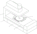
FIG. 2 is a schematic diagram of the structure of the present utility model;
FIG. 3 is a schematic view of a punching device according to the present utility model;
FIG. 4 is a schematic view of the structure of the garbage collection box of the present utility model.
In the figure: 1. a support base; 2. a body; 3. a work table; 4. a clamping device; 5. a waste collection box; 6. a punching device; 7. a motor; 8. a motor shaft; 9. a turntable; 10. an upper die; 11. a forward and reverse rotation motor; 12. a driving shaft; 13. a slide bar; 14. a clamp; 15. a rubber pad; 16. a support table; 17. a waste outlet; 18. and (5) a lower die.
Detailed Description
The following description of the embodiments of the present utility model will be made clearly and completely with reference to the accompanying drawings, in which it is apparent that the embodiments described are only some embodiments of the present utility model, but not all embodiments. All other embodiments, which can be made by those skilled in the art based on the embodiments of the utility model without making any inventive effort, are intended to be within the scope of the utility model.
Example 1
Referring to fig. 1-4, a punching device for processing includes a supporting seat 1, a top fixedly connected with organism 2 of the supporting seat 1, a top fixedly connected with workstation 3 of the organism 2, a clamping device 4 arranged in the workstation 3, a waste collection box 5 arranged at the inner side of the supporting seat 1 at the bottom of the organism 2, and a punching device 6 arranged at the top of the organism 2.
Wherein, punching device 6 includes motor 7, and motor 7's output fixedly connected with motor shaft 8, motor shaft 8's bottom fixedly connected with carousel 9, and mould 10 is installed to carousel 9's bottom, and mould 10 is provided with four groups on each, and mould 10's size is all different on the group, and lower mould 18 is provided with four groups that correspond with last mould 10, can use different moulds to punch a hole to the iron ladle of different models.
Wherein, clamping device 4 includes positive and negative rotation motor 11, positive and negative rotation motor 11's output fixedly connected with driving shaft 12, and the inside of workstation 3 is located driving shaft 12's right side fixedly connected with slide bar 13, and driving shaft 12's externally mounted has anchor clamps 14, and anchor clamps 14's outside fixedly connected with rubber pad 15, and brace table 16 has been seted up to workstation 3's inside, and waste outlet 17 has been seted up to workstation 3's inside bottom that is located brace table 16, and brace table 16's top is provided with bed die 18.
Wherein, anchor clamps 14 are provided with two, and the outside of driving shaft 12 is provided with the screw thread, and the position that is close to left side anchor clamps 14 sets up to the cis thread, and the position that is close to right side anchor clamps 14 sets up to the trans thread, and left side anchor clamps 14 and right side anchor clamps 14 are inside to be provided with corresponding screw thread, and the anchor clamps can remove when driving shaft 12 rotates.
Working principle: when the punching device for processing is used, the lower die 18 is selected according to the type of the iron can, the lower die is arranged above the supporting table 16, the forward and reverse rotating motor 11 is started to drive the driving shaft 12 to rotate, the driving shaft 12 drives the clamp 14 to rotate through the threaded structure, the slide rod 13 is connected inside the clamp 14 in a sliding manner, the slide rod 13 has a fixing effect on the clamp 14, the clamp 14 cannot rotate, so that the clamp 14 starts to move relatively, when the clamp 14 touches the lower die, the forward and reverse rotating motor 11 stops to complete clamping, the rubber pad 15 can play the roles of increasing friction and the like, then the motor 7 is started to drive the motor shaft 8 to rotate, the turntable 9 starts to rotate, the upper die 10 corresponding to the lower die 18 is replaced, the replacement of the dies is completed, the operation is simple, and the dies with different sizes can punch the iron cans with different types.
Example two
Referring to fig. 1-4, further, on the basis of the first embodiment, a waste collecting box 5 is disposed at the bottom of the machine body 2 and located at the inner side of the supporting seat 1, two waste collecting boxes 5 are disposed at the supporting seat 1, the length of each waste collecting box 5 is smaller than the shortest distance between the two supporting seats 1, the width of each waste collecting box 5 is smaller than the width of each supporting seat 1, the height of each waste collecting box 5 is smaller than the height of each supporting seat 1, the waste collecting boxes 5 can be placed at the inner side of each supporting seat 1, and the diameter of each waste outlet 17 is larger than the diameter of the hole of the largest mold in the four groups of lower molds 18, so that waste can be conveniently treated.
Working principle: when the punching device for processing is used, the die punches a hole on the iron can, after one-time punching is completed, waste materials directly enter the waste material collecting box 5 through the waste material outlet 17 arranged at the middle position of the supporting table 1, the diameter of the waste material outlet 17 is larger than the diameter of the hole of the largest die in the four groups of lower dies 18, the waste materials can be conveniently collected when different dies are switched, excessive waste material accumulation on the punching device is avoided, the punching quality is influenced, and the punching device is simple in structure and convenient to operate.
Although embodiments of the present utility model have been shown and described, it will be understood by those skilled in the art that various changes, modifications, substitutions and alterations can be made therein without departing from the principles and spirit of the utility model, the scope of which is defined in the appended claims and their equivalents.
Claims (8)
1. Punching device for processing, including supporting seat (1), its characterized in that: the utility model discloses a machine tool, including supporting seat (1), top fixedly connected with organism (2), top fixedly connected with workstation (3) of organism (2), the inside of workstation (3) is provided with clamping device (4), the bottom of organism (2) is located the inboard of supporting seat (1) and is provided with waste collection box (5), punching device (6) are installed at the top of organism (2).
2. A punching device for processing according to claim 1, characterized in that: the punching device (6) comprises a motor (7), the output end of the motor (7) is fixedly connected with a motor shaft (8), the bottom of the motor shaft (8) is fixedly connected with a rotary table (9), and an upper die (10) is arranged at the bottom of the rotary table (9).
3. A punching device for processing according to claim 1, characterized in that: clamping device (4) are including positive and negative rotation motor (11), the output fixedly connected with driving shaft (12) of positive and negative rotation motor (11), the inside of workstation (3) is located right side fixedly connected with slide bar (13) of driving shaft (12), the externally mounted of driving shaft (12) has anchor clamps (14), the outside fixedly connected with rubber pad (15) of anchor clamps (14), supporting bench (16) have been seted up to the inside of workstation (3), waste outlet (17) have been seted up to the inside of workstation (3) in the bottom of supporting bench (16), the top of supporting bench (16) is provided with bed die (18).
4. A punching device for processing according to claim 1, characterized in that: the support seat (1) is provided with two, the length of garbage collection box (5) is less than the shortest distance between two support seats (1), the width of garbage collection box (5) is less than the width of support seat (1), the height of garbage collection box (5) is less than the height of support seat (1).
5. A punching device for processing according to claim 2, characterized in that: the upper dies (10) are provided with four groups, and the sizes of the upper dies (10) in each group are different.
6. A punching device for processing according to claim 3, characterized in that: the two clamps (14) are arranged, threads are arranged on the outer portion of the driving shaft (12), the position close to the left clamp (14) is set to be a forward thread, and the position close to the right clamp (14) is set to be a reverse thread.
7. A punching device for processing according to claim 3, characterized in that: the lower die (18) is provided with four groups corresponding to the upper die (10).
8. A punching device for processing according to claim 3, characterized in that: the diameter of the scrap outlet (17) is larger than the diameter of the hole of the largest mould in the four groups of lower moulds (18).
Priority Applications (1)
| Application Number | Priority Date | Filing Date | Title |
|---|---|---|---|
| CN202223199198.XU CN218982854U (en) | 2022-11-30 | 2022-11-30 | Punching device for machining |
Applications Claiming Priority (1)
| Application Number | Priority Date | Filing Date | Title |
|---|---|---|---|
| CN202223199198.XU CN218982854U (en) | 2022-11-30 | 2022-11-30 | Punching device for machining |
Publications (1)
| Publication Number | Publication Date |
|---|---|
| CN218982854U true CN218982854U (en) | 2023-05-09 |
Family
ID=86194952
Family Applications (1)
| Application Number | Title | Priority Date | Filing Date |
|---|---|---|---|
| CN202223199198.XU Active CN218982854U (en) | 2022-11-30 | 2022-11-30 | Punching device for machining |
Country Status (1)
| Country | Link |
|---|---|
| CN (1) | CN218982854U (en) |
-
2022
- 2022-11-30 CN CN202223199198.XU patent/CN218982854U/en active Active
Similar Documents
| Publication | Publication Date | Title |
|---|---|---|
| CN209868536U (en) | Supporting device convenient to adjust for die machining | |
| CN111558643A (en) | Use method of device for completing stamping, curling and sucking of metal sheet in single station | |
| CN218982854U (en) | Punching device for machining | |
| CN107309919B (en) | Betel nut fully-automatic production device | |
| CN211464891U (en) | Die punching device | |
| CN114871509A (en) | Gear shaping machining device for star wheel and outer teeth of transmission isolator | |
| CN210702179U (en) | Electronic end cover autoloading stamping equipment | |
| CN103272974A (en) | Radial-axial vertical ring rolling machine | |
| CN219444204U (en) | Perforating device for mold processing | |
| CN202037223U (en) | Numerical control metal spinning machine | |
| CN218253952U (en) | Positioning mechanism for engraving and milling machine machining | |
| CN111941693A (en) | Automatic stripping and collecting device for thin rubber plates | |
| CN201524850U (en) | Automatic precise tooth-punching dividing machine of punch | |
| CN210966664U (en) | Template bending device capable of adjusting inner height of side mold | |
| CN212190905U (en) | Mould positioning and guiding structure | |
| CN218080035U (en) | Positioning device for punching machine | |
| CN209998345U (en) | nut casting mould convenient to unload | |
| CN216397745U (en) | High-speed die for stamping belt lamination of motor rotor | |
| CN220837428U (en) | Adjustable stamping device | |
| CN213968822U (en) | Multi-station cold heading die punch forming device | |
| CN220361862U (en) | Auto parts mold processing | |
| CN213496293U (en) | Full-automatic spin riveting press riveter | |
| CN220437743U (en) | Turntable for full-automatic high-precision tooth checking machine | |
| CN214392084U (en) | Punching and indentation equipment for blade production | |
| CN219541419U (en) | Segmented bending mechanism of numerical control bending machine |
Legal Events
| Date | Code | Title | Description |
|---|---|---|---|
| GR01 | Patent grant | ||
| GR01 | Patent grant |