CN218980698U - Sewage treatment device - Google Patents
Sewage treatment device Download PDFInfo
- Publication number
- CN218980698U CN218980698U CN202223192055.6U CN202223192055U CN218980698U CN 218980698 U CN218980698 U CN 218980698U CN 202223192055 U CN202223192055 U CN 202223192055U CN 218980698 U CN218980698 U CN 218980698U
- Authority
- CN
- China
- Prior art keywords
- filter screen
- plate
- filter
- box
- fixedly connected
- Prior art date
- Legal status (The legal status is an assumption and is not a legal conclusion. Google has not performed a legal analysis and makes no representation as to the accuracy of the status listed.)
- Active
Links
Images


Classifications
-
- Y—GENERAL TAGGING OF NEW TECHNOLOGICAL DEVELOPMENTS; GENERAL TAGGING OF CROSS-SECTIONAL TECHNOLOGIES SPANNING OVER SEVERAL SECTIONS OF THE IPC; TECHNICAL SUBJECTS COVERED BY FORMER USPC CROSS-REFERENCE ART COLLECTIONS [XRACs] AND DIGESTS
- Y02—TECHNOLOGIES OR APPLICATIONS FOR MITIGATION OR ADAPTATION AGAINST CLIMATE CHANGE
- Y02W—CLIMATE CHANGE MITIGATION TECHNOLOGIES RELATED TO WASTEWATER TREATMENT OR WASTE MANAGEMENT
- Y02W10/00—Technologies for wastewater treatment
- Y02W10/10—Biological treatment of water, waste water, or sewage
Landscapes
- Water Treatment By Sorption (AREA)
Abstract
The utility model provides a sewage treatment device, which belongs to the technical field of industrial sewage discharge and comprises a support frame welded on the bottom end surface of a filter box, a water inlet pipe fixed on the upper end surface of a box cover, a water outlet pipe sleeved on the bottom end surface of the filter box and a fixing plate fixed on the bottom end surface of the box cover, wherein filter screens on two sides are fixed between the fixing plate and the inner wall surface of the filter box, a vibrating motor is fixedly arranged on the end surface of the back of the filter screen, the installation position of the filter screen is obliquely arranged, impurities in sewage can not be blocked by the vibrating motor fixed on the end surface of the back of the filter screen, the filter screen is prevented from being frequently replaced, the filter screen is matched with a port plate and a slide hopper, the impurities filtered by the filter screen can slide out through the port plate and along the slide hopper, and a flow collecting plate is fixedly connected between the bottom end surface of the tail of the slide hopper and the upper end surface of an active carbon adsorption plate, so that the sewage flowing out of the filter screen can be collected back into the filter box again to pass through the active carbon adsorption plate, and impurities in the sewage can be purified continuously.
Description
Technical Field
The utility model relates to the technical field of sewage discharge, in particular to a sewage treatment device.
Background
In the prior art, a sewage filtering device is generally used for filtering sewage, however, as sewage flows through a filter screen, solids in the sewage can adhere to the filter screen, when the sewage quantity is large, a large amount of solids can be rapidly accumulated on the filter screen, and the solids can cause water flow blockage, so that the circulation rate of the sewage flowing through the filter screen is greatly reduced, the sewage treatment efficiency is reduced, and an optimization scheme is provided for solving the problems.
Disclosure of Invention
In view of the above, the present utility model provides a sewage treatment apparatus, which can prevent solid impurities from blocking the filter screen by the vibrating motor and the filter screen installed at an inclined position, thereby improving the circulation rate of sewage flowing through the filter screen, and discharging the filtered solid impurities through the slide hopper, thereby improving the sewage treatment efficiency as a whole.
In order to solve the technical problems, the utility model provides a sewage treatment device which comprises a drain pipe, a water inlet pipe, a pipeline interface, a filter screen, a port plate, a sliding hopper, a bearing plate, an activated carbon adsorption plate, a buckle, a support frame and a filter box.
The support frame is in the terminal surface four corners department of rose box bottom through welded mode fixed connection, be in the same place through buckle fixed connection between case lid and the rose box, inlet tube fixed connection is in case lid up end, and the inlet tube divides two places water delivery, the mounting hole has been seted up to rose box bottom terminal surface central point put, the pipeline interface passes through bolted connection to be fixed in the end plate department in the mounting hole outside, the drain pipe passes through mode fixed connection at pipeline interface periphery that cup joints, fixed plate fixed connection is in the intermediate position of case lid bottom terminal surface, filter screen one end is fixed in the fixed plate outside, other end fixed connection is in the internal face of rose box both sides, and the filter screen is fixed respectively in the fixed plate both sides, be incline position fixed connection, the port board has been seted up with the closure of rose box inner wall to the filter screen tail end, and port board inclination is unanimous with the filter screen, slide hopper fixed connection is the horizontal fixation, the rose box inner wall is close to bottom terminal surface department and is provided with the bearing plate, the active carbon adsorption plate to the bearing plate top that sets up at the rose box internal face, through the bearing plate arm to active carbon adsorption plate.
As a further improvement of the utility model, the supporting frame is fixedly connected to four corners of the end face of the bottom of the filter box in a welding way, the box cover is fixedly connected with the filter box through the buckle, the water inlet pipe is fixedly connected to the upper end face of the box cover, the water inlet pipe is used for conveying water at two parts, and the height of the whole filter box is raised through the supporting frame, so that an operator can conveniently open or close the filter box through the buckle when carrying out other operations.
As a further improvement of the utility model, the center of the end face of the bottom of the filter box is provided with the mounting hole, the pipeline interface is fixed at the end plate outside the mounting hole through the bolt connection, the drain pipe is fixedly connected at the periphery of the pipeline interface in a sleeved mode, and the drain pipe can be timely maintained and replaced by fire when damaged in a sleeved mode, thereby avoiding delaying the normal operation of work and saving labor.
As a further improvement of the utility model, the fixed plate is fixedly connected to the middle position of the end face of the bottom of the box cover, one end of the filter screen is fixed on the outer side of the fixed plate, the other end of the filter screen is fixedly connected to the inner wall faces of the two sides of the filter box, the filter screens are respectively fixed on the two sides of the fixed plate and are fixedly connected in an inclined position, the end face of the back of the filter screen is fixedly provided with the vibrating motor, the installation position of the filter screen is inclined through the fixed plate, and then sundries in sewage can not block the filter screen rapidly through the vibrating motor fixed on the end face of the back of the filter screen, so that the filter screen is prevented from being replaced frequently, and the working efficiency is reduced.
As a further improvement of the utility model, a port plate is arranged at the closed position of the tail end of the filter screen and the inner wall of the filter box, the inclination angle of the port plate is consistent with that of the filter screen, the sliding hopper is fixedly connected to the tail part of the port plate and is horizontally fixed, and sundries filtered by the filter screen can slide out along the sliding hopper through the port plate by the cooperation of the opened port plate, the sliding hopper and the vibrating motor.
As a further improvement of the utility model, one side of the flow collecting plate is fixedly connected to the bottom end face of the tail part of the sliding hopper, the other side of the flow collecting plate is fixedly connected to the upper end face of the active carbon adsorption plate, the flow collecting plate is obliquely arranged, and sewage flowing out of the filter screen can be collected back into the filter box again through the flow collecting plate, so that the sewage which is not purified is prevented from flowing out of the filter box.
As a further improvement of the utility model, the bearing plate is arranged on the inner wall of the filter box near the end face of the bottom, the active carbon adsorption plate is supported above the bearing plate arranged on the inner wall of the filter box, and the active carbon adsorption plate is supported by the bearing plate, so that the active carbon adsorption plate can be conveniently taken, replaced or cleaned when the adsorptivity of the active carbon adsorption plate is poor.
In summary, compared with the prior art, the present application includes at least one of the following beneficial technical effects:
1. the device passes through the slope mounted position of filter screen and vibrating motor's cooperation for the sewage that both sides flowed down can flow to the port board through vibrating motor's vibrations and the inclination of filter screen along the trend, and the debris in the sewage can not block up the filter screen fast, avoids reducing the circulation rate that the sewage flows through the filter screen by a wide margin, leads to often changing the filter screen, reduces work efficiency, and the debris after its filtration can be discharged through the slide hopper.
2. The device is characterized in that the flow collecting plate is fixedly connected between the bottom end face of the tail part of the sliding hopper and the upper end face of the active carbon adsorption plate, sewage flowing out of the filter screen can be collected back into the filter box again by utilizing the inclined arrangement of the flow collecting plate, the sewage which is not purified is prevented from flowing out of the filter box, and then the sewage is enabled to continuously pass through the active carbon adsorption plate, so that impurities in the sewage are continuously purified.
3. In the device, the inlet tube that the case lid up end is connected divide into two way branch pipes and pours into sewage into in the rose box into, can avoid too much debris to pile up together, blocks up the inlet tube, and inlet tube and drain pipe all fix in the pipeline interface outside through the mode of cup jointing, can dismantle fast when the damage takes place for any water pipe, maintains or change it.
Drawings
FIG. 1 is an oblique view showing the overall structure of a sewage treatment apparatus of the present utility model;
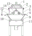
FIG. 2 is a front view of the sewage treatment apparatus of the present utility model;
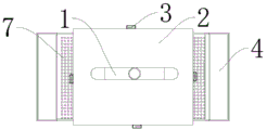
FIG. 3 is a plan view of the sewage treatment apparatus of the present utility model;
FIG. 4 is a full sectional view of the sewage treatment apparatus of the present utility model;
1. a water inlet pipe; 2. a case cover; 3. a buckle; 4. a slide hopper; 5. a filter box; 6. a support frame; 7. a port plate; 8. a flow collecting plate; 9. an activated carbon adsorption plate; 10. a bearing plate; 11. a drain pipe; 12. a vibration motor; 13. a fixing plate; 14. and (3) a filter screen.
Detailed Description
In order to make the objects, technical solutions and advantages of the embodiments of the present utility model more clear, the technical solutions of the embodiments of the present utility model will be clearly and completely described below with reference to fig. 1 to 4 of the embodiments of the present utility model. It will be apparent that the described embodiments are some, but not all, embodiments of the utility model. All other embodiments, which are obtained by a person skilled in the art based on the described embodiments of the utility model, fall within the scope of protection of the utility model.
As shown in fig. 1-4: this embodiment provides a sewage treatment plant, including drain pipe 11, inlet tube 1, the pipeline interface, filter screen 14, the port board 7, slide hopper 4, the bearing plate 10, active carbon adsorption plate 9, buckle 3, support frame 6 and rose box 5, support frame 6 is through welded mode fixed connection in rose box 5 bottom terminal surface four corners department, be in the same place through buckle 3 fixed connection between case lid 2 and the rose box 5, inlet tube 1 fixed connection is at case lid 2 up end, and inlet tube 1 divides two water delivery, the mounting hole has been seted up in rose box 5 bottom terminal surface central point put, pipeline interface passes through bolted connection to be fixed in the end plate department in the mounting hole outside, drain pipe 11 passes through the mode fixed connection who cup joints at pipeline interface periphery, fixed plate 13 fixed connection is in the intermediate position of case lid 2 bottom terminal surface, filter screen 14 one end is fixed in the fixed plate 13 outside, other end fixed connection is in the internal face of rose box 5 both sides, and filter screen 14 is inclined position fixed connection respectively, port board 7 has been seted up to port board 7 in the closed department of filter box 5 internal wall, and port board 7 inclination is unanimous with hopper 4, port board 7 is fixed connection at the end plate 7 is in the end plate 10 side of the side of being close to the filter box 5, the active carbon adsorption plate 10 is arranged to the bearing plate 10, the bearing plate is arranged to the bearing plate 10.
According to one embodiment of the utility model, as shown in fig. 1 and 4, the fixing plate 13 is fixedly connected to the middle position of the end surface of the bottom of the tank cover 2, one end of the filter screen 14 is fixed on the outer side of the fixing plate 13, the other end of the filter screen 14 is fixedly connected to the inner wall surfaces of two sides of the filter tank 5, the filter screens 14 are respectively fixed on two sides of the fixing plate 13 and are fixedly connected in inclined positions, the closed position of the tail end of the filter screen 14 and the inner wall of the filter tank 5 is provided with the port plate 7, the inclined angle of the port plate 7 is consistent with that of the filter screen 14, the sliding hopper 4 is fixedly connected to the tail end of the port plate 7 and is horizontally fixed, the device enables sewage flowing down from two sides to flow to the port plate 7 in a clockwise manner through the vibration of the vibration motor 12 and the inclined angle of the filter screen 14, sundries in the sewage can not quickly block the filter screen 14, the circulation rate of the sewage flowing through the filter screen 14 is prevented from being greatly reduced, the frequent replacement of the filter screen 14 is reduced, the working efficiency is reduced, the sundries after the filtration can be discharged through the sliding hopper 4.
According to another embodiment of the utility model, as shown in fig. 2 and 4, one side of the flow collecting plate 8 is fixedly connected to the bottom end face of the tail of the sliding hopper 4, the other side of the flow collecting plate 8 is fixedly connected to the upper end face of the activated carbon adsorption plate 9, the flow collecting plate 8 is obliquely arranged, a bearing plate 10 is arranged on the inner wall of the filter box 5 near the bottom end face, the activated carbon adsorption plate 9 is carried above the bearing plate 10 arranged on the inner wall face of the filter box 5, the bearing plate 10 is carried to the activated carbon adsorption plate 9, the flow collecting plate 8 is fixedly connected between the bottom end face of the tail of the sliding hopper 4 and the upper end face of the activated carbon adsorption plate 9, and sewage flowing out of the filter screen 14 can be collected back into the filter box 5 again by utilizing the oblique arrangement of the flow collecting plate 8, so that the sewage which is not purified is prevented from flowing out of the filter box 5, and then the sewage continues to be purified by the activated carbon adsorption plate 9.
In one embodiment of the utility model, as shown in fig. 1-4, a box cover 2 and a filter box 5 are fixedly connected together through a buckle 3, a water inlet pipe 1 is fixedly connected to the upper end face of the box cover 2, the water inlet pipe 1 is used for conveying water at two positions, a mounting hole is formed in the center of the end face of the bottom of the filter box 5, a pipeline interface is fixedly connected to an end plate outside the mounting hole through bolts, a water outlet pipe 11 is fixedly connected to the periphery of the pipeline interface in a sleeving manner, in the device, the water inlet pipe 1 connected to the upper end face of the box cover 2 is divided into two branch pipes to inject sewage into the filter box 5, so that excessive sundries can be prevented from accumulating together, the water inlet pipe 1 is blocked, the water inlet pipe 1 and the water outlet pipe 11 are both fixed to the outer side of the pipeline interface in a sleeving manner, and the water inlet pipe can be quickly detached for maintenance or replacement when any water pipe is damaged.
While the foregoing is directed to the preferred embodiments of the present utility model, it will be appreciated by those skilled in the art that various modifications and adaptations can be made without departing from the principles of the present utility model, and such modifications and adaptations are intended to be comprehended within the scope of the present utility model.
Claims (7)
1. The utility model provides a sewage treatment plant, includes drain pipe (11), inlet tube (1), support frame (6) and rose box (5), its characterized in that: support frame (6) set up at rose box (5) bottom terminal surface, rose box (5) bottom terminal surface is provided with the pipeline interface, drain pipe (11) are connected in pipeline interface department, rose box (5) up end is provided with case lid (2), and case lid (2) up end is connected with inlet tube (1), rose box (5) inside is provided with fixed plate (13), be provided with filter screen (14) between rose box (5) internal face and fixed plate (13), port board (7) have been seted up to filter screen (14) tail end department, and port board (7) department is provided with smooth hopper (4), and smooth hopper (4) afterbody bottom terminal surface is provided with gathers flow board (8), rose box (5) inner chamber bottom terminal surface is provided with active carbon adsorption board (9).
2. The wastewater treatment apparatus of claim 1, wherein: the support frame (6) is fixedly connected to four corners of the end face of the bottom of the filter box (5) in a welding mode, the box cover (2) is fixedly connected with the filter box (5) through the buckle (3), the water inlet pipe (1) is fixedly connected to the upper end face of the box cover (2), and the water inlet pipe (1) is used for conveying water in two parts.
3. The wastewater treatment apparatus of claim 2, wherein: the central position of the end face of the bottom of the filter box (5) is provided with a mounting hole, the pipeline interface is fixedly connected with an end plate at the outer side of the mounting hole through a bolt, and the drain pipe (11) is fixedly connected with the periphery of the pipeline interface in a sleeving manner.
4. The wastewater treatment apparatus of claim 1, wherein: the filter screen (14) is characterized in that the fixing plate (13) is fixedly connected to the middle position of the end face of the bottom of the box cover (2), one end of the filter screen (14) is fixed to the outer side of the fixing plate (13), the other end of the filter screen is fixedly connected to the inner wall faces of the two sides of the filter box (5), the filter screens (14) are respectively fixed to the two sides of the fixing plate (13) and are fixedly connected in an inclined position, and the end face of the back of the filter screen (14) is fixedly provided with the vibrating motor (12).
5. The wastewater treatment apparatus of claim 1, wherein: the end of the filter screen (14) is provided with a port plate (7) at the closed position of the inner wall of the filter tank (5), the inclination angle of the port plate (7) is consistent with that of the filter screen (14), and the sliding hopper (4) is fixedly connected to the tail of the port plate (7) and is horizontally fixed.
6. The wastewater treatment apparatus according to claim 5, wherein: one side of the flow collecting plate (8) is fixedly connected to the bottom end face of the tail of the sliding hopper (4), the other side of the flow collecting plate is fixedly connected to the upper end face of the activated carbon adsorption plate (9), and the flow collecting plate (8) is obliquely arranged.
7. The wastewater treatment apparatus according to claim 6, wherein: the filter box (5) inner wall is provided with bearing plate (10) near bottom terminal surface department, and active carbon adsorption board (9) bear to bearing plate (10) top that sets up at filter box (5) inner wall.
Priority Applications (1)
| Application Number | Priority Date | Filing Date | Title |
|---|---|---|---|
| CN202223192055.6U CN218980698U (en) | 2022-12-01 | 2022-12-01 | Sewage treatment device |
Applications Claiming Priority (1)
| Application Number | Priority Date | Filing Date | Title |
|---|---|---|---|
| CN202223192055.6U CN218980698U (en) | 2022-12-01 | 2022-12-01 | Sewage treatment device |
Publications (1)
| Publication Number | Publication Date |
|---|---|
| CN218980698U true CN218980698U (en) | 2023-05-09 |
Family
ID=86216928
Family Applications (1)
| Application Number | Title | Priority Date | Filing Date |
|---|---|---|---|
| CN202223192055.6U Active CN218980698U (en) | 2022-12-01 | 2022-12-01 | Sewage treatment device |
Country Status (1)
| Country | Link |
|---|---|
| CN (1) | CN218980698U (en) |
-
2022
- 2022-12-01 CN CN202223192055.6U patent/CN218980698U/en active Active
Similar Documents
| Publication | Publication Date | Title |
|---|---|---|
| CN213433362U (en) | Filter equipment with multistage screening function | |
| CN207811507U (en) | A kind of movable type river regulation tail water processing unit | |
| CN218980698U (en) | Sewage treatment device | |
| CN208667290U (en) | A kind of aluminium purification waste water processing unit | |
| CN208815647U (en) | A kind of water pipeline for hydraulic engineering | |
| CN208626699U (en) | Efficient sedimentation tank and sewage disposal system | |
| CN214302063U (en) | Sewage pipeline slag removal assembly | |
| CN106693468B (en) | A kind of rain water drainage purification and storage system | |
| CN210631769U (en) | Novel pipeline impurity remover | |
| CN209917419U (en) | Manual filter | |
| CN208626698U (en) | High sludge condensation rate sedimentation basin and sewage disposal system | |
| CN209778348U (en) | Closed water conservancy sieve grid device | |
| CN209348184U (en) | A kind of inclined-plate clarifying basin based on active iron medicament | |
| CN215610230U (en) | Dust suppression structure of building construction material screening machine | |
| CN214914865U (en) | Anti-blocking type desulfurizing tower | |
| CN207944546U (en) | Unpowered rainwater runoff pollution object cuts dirty facility | |
| CN219167991U (en) | Air purifying equipment with hierarchical filtration function | |
| CN217939474U (en) | Pipeline slag removal device | |
| CN209378642U (en) | A kind of industrial dedusting device | |
| CN217939328U (en) | Box filter | |
| CN214781181U (en) | Chemical plant circulating water cleaning pipeline filter equipment | |
| CN221181841U (en) | Environmental pollution purifying structure | |
| CN220266799U (en) | Drainage device for building engineering | |
| CN219689373U (en) | Industrial sewage treatment device capable of preventing blockage | |
| CN220918439U (en) | Agricultural irrigation fine filtering device suitable for different water sources |
Legal Events
| Date | Code | Title | Description |
|---|---|---|---|
| GR01 | Patent grant | ||
| GR01 | Patent grant |