CN218965002U - Steel grinding device - Google Patents
Steel grinding device Download PDFInfo
- Publication number
- CN218965002U CN218965002U CN202222677696.4U CN202222677696U CN218965002U CN 218965002 U CN218965002 U CN 218965002U CN 202222677696 U CN202222677696 U CN 202222677696U CN 218965002 U CN218965002 U CN 218965002U
- Authority
- CN
- China
- Prior art keywords
- dust
- frame
- cooling
- steel
- dust collecting
- Prior art date
- Legal status (The legal status is an assumption and is not a legal conclusion. Google has not performed a legal analysis and makes no representation as to the accuracy of the status listed.)
- Active
Links
Images


Classifications
-
- Y—GENERAL TAGGING OF NEW TECHNOLOGICAL DEVELOPMENTS; GENERAL TAGGING OF CROSS-SECTIONAL TECHNOLOGIES SPANNING OVER SEVERAL SECTIONS OF THE IPC; TECHNICAL SUBJECTS COVERED BY FORMER USPC CROSS-REFERENCE ART COLLECTIONS [XRACs] AND DIGESTS
- Y02—TECHNOLOGIES OR APPLICATIONS FOR MITIGATION OR ADAPTATION AGAINST CLIMATE CHANGE
- Y02P—CLIMATE CHANGE MITIGATION TECHNOLOGIES IN THE PRODUCTION OR PROCESSING OF GOODS
- Y02P70/00—Climate change mitigation technologies in the production process for final industrial or consumer products
- Y02P70/10—Greenhouse gas [GHG] capture, material saving, heat recovery or other energy efficient measures, e.g. motor control, characterised by manufacturing processes, e.g. for rolling metal or metal working
Abstract
The utility model discloses a steel polishing device, which comprises a frame, wherein sliding grooves are formed in two sides of the inside of the frame, fixing devices are arranged on the sliding grooves, dust collecting devices are arranged at the bottom of the frame, steerable idler wheels are arranged at the bottom of the dust collecting devices, a cooling device is arranged at the top of the frame, a guide rail is arranged at the middle part of the bottom of the cooling device, a traction device is movably clamped on the surface of the guide rail, a polishing device is arranged at the bottom of the traction device, a rotating device is arranged at the bottom of the traction device on one side of the polishing device, the steel polishing device adopts the fixing devices and the polishing device, the processing time is saved, a rotating cavity is matched with a telescopic cavity, and meanwhile, the traction device is responsible for moving, so that the steel processing speed can be accelerated, the polishing efficiency is improved, and waste scraps generated in the processing process enter a dust collecting plate through a dust filtering net to finish collection, thereby providing convenience for processing work and improving the working environment.
Description
Technical Field
The utility model relates to the technical field of steel polishing equipment, in particular to a steel polishing device.
Background
In the technical field of machining, some steels need to be removed rust on the surfaces of the steels before welding, the rust is removed by removing rust on the whole surfaces of the steel plates, a common rust removing device at present is divided into a manual and mechanical structure, and the traditional polishing machines have the problems of uneven polishing, large use limitation, easy overheating of equipment, flying rust in the polishing process, certain potential safety hazard and the like.
Disclosure of Invention
Technical problem to be solved
Aiming at the defects of the prior art, the utility model provides a steel polishing device which has the advantages of convenient operation, convenient cooling and fixing, convenient polishing effect, convenient rust scrap treatment and the like, solves the problems that common steels are not polished uniformly, equipment is easy to overheat, scraps fly, production efficiency is reduced, and potential safety hazards are brought to operators.
Two technical schemes
In order to achieve the purposes of convenient operation and good cooling and temperature regulating effects, the utility model provides the following technical scheme: the utility model provides a steel grinding device, includes the frame, the sliding tray has been seted up to the inside both sides of frame, install fixing device on the sliding tray, dust collecting device is installed to the frame bottom, steerable gyro wheel is installed to dust collecting device bottom, cooling device is installed at the frame top, cooling device bottom middle part and at the inside top of frame install the guide rail, the guide rail is the indent, crashproof groove has all been seted up to the inside both sides of guide rail, guide rail surface activity joint has draw-in gear, the grinding device is installed to the draw-in gear bottom, install rotary device on the draw-in gear bottom of grinding device one side.
Preferably, the number of the steerable rollers is not less than that of the dust collecting device, the steerable rollers are arranged in parallel, and rubber pads are arranged at the connecting positions of the steerable rollers and the dust collecting device.
Preferably, the dust collecting device comprises a dust collecting plate, a dust falling slope is arranged at the top of the dust collecting plate, an air injection pipe is arranged on one side of the dust falling slope, a supporting leg is arranged on one side, far away from the air injection pipe, of the dust falling slope, the supporting leg is fixedly arranged at the top of the dust collecting plate, a drawer is arranged at the top of the dust collecting plate and in the middle of the supporting leg, a handle is arranged on the surface of the drawer, and a dust filtering net is arranged at the tops of the dust falling slope and the supporting leg.
Preferably, the cooling device comprises a cooling shell, cooling fans are arranged inside the cooling shell, the number of the cooling fans is not less than 3, the cooling fans are arranged in parallel, and a protective cover is arranged at the bottom of the cooling shell.
Preferably, according to the steel polishing device of claim, the fixing device comprises a fixing piece, the bottom of the fixing piece is installed on the sliding groove, the top of the fixing piece is provided with a buffer cushion, the top of the buffer cushion is provided with a compression spring, the top of the compression spring is provided with a fixing clip, the top of the fixing clip is provided with sand paper, and the fixing devices are not less than one and are arranged in parallel.
Preferably, the traction device comprises a traction motor, anti-collision pads are arranged on two sides of the traction motor, the anti-collision pads are movably arranged in anti-collision grooves in the guide rails, a fixed column is fixedly arranged at the bottom of the traction motor, a stabilizing arm is movably sleeved at the bottom of the fixed column, a telescopic arm is movably sleeved at the bottom of the stabilizing arm, a sanding device and a rotating device can be fixedly clamped at the bottom of the telescopic arm, and the two traction devices can draw one rotating device.
Preferably, the grinding device comprises a rotating shaft, the top of the rotating shaft is fixedly clamped with a telescopic arm, the bottom of the rotating shaft is provided with a grinding wheel, and the grinding wheel can be changed according to the use requirement of an operator.
Preferably, the rotating device comprises a telescopic cavity, a telescopic arm is fixedly clamped at the top of the telescopic cavity, the inner wall of the telescopic cavity is made of flexible materials, a rotating cavity is fixedly sleeved in the telescopic cavity, and protruding small teeth are arranged on the inner wall of the rotating cavity.
Three beneficial effects
Compared with the prior art, the utility model has the beneficial effects that: this steel grinding device adopts fixing device and dull polish device, the time of processing has been practiced thrift, adopt rotatory chamber and flexible chamber cooperation, simultaneously be responsible for removing by draw gear, can accelerate steel processing speed, improve the efficiency of polishing, the sweeps that produce in the course of the treatment pass through the dust filter net, fall the dirt slope, get into the dust collecting plate, accomplish and collect, it is convenient to provide for sweeps processing work, operational environment has been improved, compression spring in the fixing device can be fixed according to the steel automatic clamping that will polish, the tiny tooth in the rotatory intracavity wall also can assist fixed steel, the crashproof groove in the guide rail is installed to crashproof pad on the draw gear, the stability of whole device operation has been guaranteed, and is convenient for operation, the cooling, it is fixed convenient, the effect of polishing, the iron rust sweeps treatment effect is better for traditional mode.
Drawings
FIG. 1 is a schematic diagram of the structure of the present utility model;
FIG. 2 is a schematic view of a dust collecting device according to the present utility model
FIG. 3 is a schematic view of a cooling device according to the present utility model;
FIG. 4 is a schematic view of a fixing device according to the present utility model;
FIG. 5 is a schematic view of the traction device and sanding device of the present utility model;
fig. 6 is a schematic structural view of a traction device and a rotation device according to the present utility model.
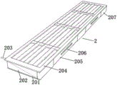
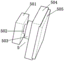
In the figure: 1. a frame; 2. a dust collecting device; 201. a dust collecting plate; 202. falling dust slope; 203. an air injection pipe; 204. a dust filtering net; 205. a drawer; 206. a handle; 207. a support leg; 3. a steerable roller; 4. a cooling device; 401. cooling the housing; 402. a protective cover; 403. a cooling fan; 5. a fixing device; 501. a fixing member; 502. a cushion pad; 503. a compression spring; 504. a fixing clamp; 505. sand paper; 6. a guide rail; 7. a traction device; 701. a traction motor; 702. a crash pad; 703. fixing the column; 704. a stabilizing arm; 705. a telescoping arm; 8. a sanding device; 801. a rotation shaft; 802. grinding wheel; 9. a rotating device; 901. a telescopic chamber; 902. and rotating the cavity.
Detailed Description
The following description of the embodiments of the present utility model will be made clearly and completely with reference to the accompanying drawings, in which it is apparent that the embodiments described are only some embodiments of the present utility model, but not all embodiments. All other embodiments, which can be made by those skilled in the art based on the embodiments of the utility model without making any inventive effort, are intended to be within the scope of the utility model.
Referring to fig. 1-6, the present utility model provides a technical solution: the utility model provides a steel grinding device, which comprises a frame 1, the sliding tray has been seted up to the inside both sides of frame 1, install fixing device 5 on the sliding tray, dust collection device 2 is installed to frame 1 bottom, steerable gyro wheel 3 is installed to dust collection device 2 bottom, but the quantity of steering gyro wheel 3 is not less than 4, and parallel juxtaposition sets up between steerable gyro wheel 3, the rubber pad is installed to steerable gyro wheel 3 and dust collection device 2's junction, cooling device 4 is installed at frame 1 top, cooling device 4 bottom middle part and at frame 1 inside top install guide rail 6, guide rail 6 is indent formula, the anticollision groove has all been seted up to guide rail 6 inside both sides, guide rail 6 surface activity joint has draw gear 7, grinding device 8 is installed to draw gear 7 bottom, install rotary device 9 on the draw gear 7 bottom of grinding device 8 one side.
Referring to fig. 2, the dust collecting device 2 includes a dust collecting plate 201, a dust falling slope 202 is installed at the top of the dust collecting plate 201, an air injection pipe 203 is installed at one side of the dust falling slope 202, a supporting leg 207 is installed at one side of the dust falling slope 202 far away from the air injection pipe 203, the supporting leg 207 is fixedly installed at the top of the dust collecting plate 201, a drawer 205 is installed at the top of the dust collecting plate 201 and in the middle of the supporting leg 207, a handle 206 is installed on the surface of the drawer 205, dust filtering nets 204 are installed at the tops of the dust falling slope 202 and the supporting leg 207, and scraps generated in the processing process enter the dust collecting plate 201 through the dust filtering nets 204, thus completing collection, providing convenience for the scrap processing work and improving the working environment.
Referring to fig. 3, the cooling device 4 includes a cooling housing 401, cooling fans 403 are disposed inside the cooling housing 401, not less than 3 cooling fans 403 are disposed in parallel, a protection cover 402 is mounted at the bottom of the cooling housing 401, and when polishing is performed, the cooling fans 403 are started to cool the device, so that the working efficiency is maintained.
Referring to fig. 4, the fixing device 5 includes a fixing member 501, the bottom of the fixing member 501 is mounted on a sliding groove, a buffer pad 502 is mounted on the top of the fixing member 501, a compression spring 503 is mounted on the top of the buffer pad 502, a fixing clip 504 is mounted on the top of the compression spring 503, sand paper 505 is mounted on the top of the fixing clip 504, at least 4 fixing devices 5 are arranged in parallel, and the compression springs 503 in the fixing device 5 can be automatically clamped and fixed according to steel to be polished.
Referring to fig. 5, the traction device 7 includes a traction motor 701, anti-collision pads 702 are mounted on two sides of the traction motor 701, the anti-collision pads 702 are movably mounted in anti-collision grooves in the guide rail 6, a fixed column 703 is fixedly mounted at the bottom of the traction motor 701, a stabilizing arm 704 is movably sleeved at the bottom of the fixed column 703, a telescopic arm 705 is movably sleeved at the bottom of the stabilizing arm 704, a grinding device 8 and a rotating device 9 can be fixedly clamped at the bottom of the telescopic arm 705, the anti-collision pads 702 on the traction device 7 are mounted in the anti-collision grooves in the guide rail 6, running stability of the whole device is guaranteed, the grinding device 8 includes a rotating shaft 801, the telescopic arm 705 is fixedly clamped at the top of the rotating shaft 801, grinding wheels 802 are mounted at the bottom of the rotating shaft 801, and the grinding wheels 802 can be replaced according to use demands of operators.
Referring to fig. 6, the rotating device 9 includes a telescopic cavity 901, a telescopic arm 705 is fixedly clamped at the top of the telescopic cavity 901, the inner wall of the telescopic cavity 901 is made of flexible material, a rotating cavity 902 is fixedly sleeved in the telescopic cavity 901, protruding small teeth are mounted on the inner wall of the rotating cavity 902, and the small teeth in the inner wall of the rotating cavity 902 can also assist in fixing steel.
During polishing, firstly, a grinding wheel 802 with proper mesh number is arranged on a polishing device 8, a cooling device 4 is started, a cooling fan 403 is started, the temperature of the device is reduced, a traction device 7 at the top of a rotary device 9 is started, a telescopic arm 705 in the traction device 7 is started, the rotary device 9 is adjusted to a proper position, steel to be processed is put into a rotary cavity 902, a fixing device 5 is started, a compression spring 503 in the fixing device 5 is released, a fixing clamp 504 clamps and fixes the steel, a cushion pad 502 ensures stable operation of the fixing device 5, the inner wall of the telescopic cavity 901 is tightened, the rotary cavity 902 is extruded, small teeth of the rotary cavity 902 assist in fixing the steel, then the traction device 7 on the polishing device 8 is started, the telescopic arm 705 in the traction device 7 falls down, the polishing device 8 is adjusted at a steel polishing position, after polishing time is finished, the rotary cavity 902 rotates to adjust the angle of the steel, polishing treatment is performed again, waste scraps generated by polishing are thrown out of the steel through a dust filtering net 204, a falling slope 202 enters a dust collecting plate 201, after polishing is finished, the telescopic cavity 901 clamps the steel, and the steel is clamped and the steel is finished.
When the waste disposal work is performed, the pressure is introduced into the air injection pipe 203, the waste entering the dust collection plate 201 enters the drawer 205 due to the pressure, the pressure is stopped from being introduced into the air injection pipe 203, the handle 206 is pulled, the drawer 205 is opened, the waste is poured out, and the drawer 205 is restored, so that the waste disposal work is completed.
To sum up, this steel grinding device, adopt fixing device 5 and dull polish device 8, the time of processing has been practiced thrift, adopt rotatory chamber 902 and flexible chamber 901 cooperation, simultaneously be responsible for removing by draw gear 7, can accelerate steel processing speed, improve the efficiency of polishing, sweeps that produce in the course of the treatment pass through dust filter 204 simultaneously, fall the dirt slope 202, get into dust collecting plate 201, accomplish and collect, it is convenient to handle work for sweeps, working environment has been improved, compression spring 503 in fixing device 5 can be according to the steel automatic clamping who will polish is fixed, the tooth in the rotatory chamber 902 inner wall also can assist fixed steel, crashproof pad 702 on the draw gear 7 is installed in the crashproof groove in guide rail 6, the stability of whole device operation has been guaranteed, and is convenient for operation, the cooling, it is fixed convenient, the effect of polishing, the iron rust sweeps treatment effect is better for traditional mode.
Although embodiments of the present utility model have been shown and described, it will be understood by those skilled in the art that various changes, modifications, substitutions and alterations can be made therein without departing from the principles and spirit of the utility model, the scope of which is defined in the appended claims and their equivalents.
Claims (8)
1. Steel grinding device, including frame (1), its characterized in that: the utility model discloses a dust collector for the dust collector of the utility model discloses a dust collector of the utility model, including frame (1), fixing device (5) have been seted up to inside both sides of frame (1), dust collector (2) are installed to frame (1) bottom, steerable gyro wheel (3) are installed to dust collector (2) bottom, cooling device (4) are installed at frame (1) top, guide rail (6) are installed at cooling device (4) bottom middle part and at frame (1) inside top, guide rail (6) are the indent, crashproof groove has all been seted up to guide rail (6) inside both sides, guide rail (6) surface activity joint has draw gear (7), grinding device (8) are installed to draw gear (7) bottom, install rotary device (9) on the draw gear (7) bottom of grinding device (8) one side.
2. A steel grinding device according to claim 1, wherein: the number of the steerable rollers (3) is not less than 4, the steerable rollers (3) are arranged in parallel, and rubber pads are arranged at the connecting positions of the steerable rollers (3) and the dust collecting device (2).
3. A steel grinding device according to claim 1, wherein: dust collection device (2) are including dust collecting plate (201), dust falling slope (202) are installed at dust collecting plate (201) top, gas injection pipe (203) are installed to one side of dust falling slope (202), landing leg (207) are installed to one side that gas injection pipe (203) were kept away from to dust falling slope (202), landing leg (207) fixed mounting is at the top of dust collecting plate (201), drawer (205) are installed at dust collecting plate (201) top and in the middle of landing leg (207), drawer (205) surface mounting has handle (206), dust filtering net (204) are installed at dust falling slope (202) and landing leg (207) top.
4. A steel grinding device according to claim 1, wherein: the cooling device (4) comprises a cooling shell (401), cooling fans (403) are arranged inside the cooling shell (401), the number of the cooling fans (403) is not less than 3, the cooling fans are arranged in parallel, and a protective cover (402) is arranged at the bottom of the cooling shell (401).
5. A steel grinding device according to claim 1, wherein: fixing device (5) are including mounting (501), the bottom of mounting (501) is installed on the sliding tray, blotter (502) are installed at the top of mounting (501), compression spring (503) are installed at the top of blotter (502), fixation clamp (504) are installed at compression spring (503) top, sand paper (505) are installed at the top of fixation clamp (504), fixing device (5) are not less than 4, all parallel arrangement.
6. A steel grinding device according to claim 1, wherein: traction device (7) are including traction motor, anticollision pad (702) are all installed to traction motor's both sides, anticollision pad (702) movable mounting is in the crashproof groove in guide rail (6), traction motor's bottom fixed mounting has fixed column (703), stable arm (704) have been cup jointed in the activity of fixed column (703) bottom, flexible arm (705) have been cup jointed in the activity of stable arm (704) bottom, but flexible arm (705) bottom fixed joint has dull polish device (8) and rotary device (9).
7. A steel grinding apparatus as set forth in claim 5 wherein: the grinding device (8) comprises a rotating shaft (801), a telescopic arm (705) is fixedly clamped at the top of the rotating shaft (801), and a grinding wheel (802) is mounted at the bottom of the rotating shaft (801).
8. A steel grinding apparatus as set forth in claim 5 wherein: the rotating device (9) comprises a telescopic cavity (901), a telescopic arm (705) is fixedly clamped at the top of the telescopic cavity (901), the inner wall of the telescopic cavity (901) is made of flexible materials, a rotating cavity (902) is fixedly sleeved in the telescopic cavity (901), and protruding small teeth are mounted on the inner wall of the rotating cavity (902).
Priority Applications (1)
| Application Number | Priority Date | Filing Date | Title |
|---|---|---|---|
| CN202222677696.4U CN218965002U (en) | 2022-10-11 | 2022-10-11 | Steel grinding device |
Applications Claiming Priority (1)
| Application Number | Priority Date | Filing Date | Title |
|---|---|---|---|
| CN202222677696.4U CN218965002U (en) | 2022-10-11 | 2022-10-11 | Steel grinding device |
Publications (1)
| Publication Number | Publication Date |
|---|---|
| CN218965002U true CN218965002U (en) | 2023-05-05 |
Family
ID=86162134
Family Applications (1)
| Application Number | Title | Priority Date | Filing Date |
|---|---|---|---|
| CN202222677696.4U Active CN218965002U (en) | 2022-10-11 | 2022-10-11 | Steel grinding device |
Country Status (1)
| Country | Link |
|---|---|
| CN (1) | CN218965002U (en) |
-
2022
- 2022-10-11 CN CN202222677696.4U patent/CN218965002U/en active Active
Similar Documents
| Publication | Publication Date | Title |
|---|---|---|
| CN111571226A (en) | Stainless steel plate cutting processing device | |
| CN112276715A (en) | Uniform-deburring casting production and processing deburring equipment | |
| CN218965002U (en) | Steel grinding device | |
| CN208132613U (en) | Dust-extraction unit is used in a kind of processing of honing machine | |
| CN220178982U (en) | Brake block abrasive machining equipment | |
| CN112917349A (en) | Sample steel rail web rust removal device and method | |
| CN209579074U (en) | A kind of machine components grinding device convenient for collecting waste material | |
| CN210132328U (en) | Clamping protection device for manufacturing motor rotating shaft | |
| CN217394522U (en) | A grinding device for mechanical equipment corner burr | |
| CN216422206U (en) | Special-shaped sander with dust absorption and treatment functions | |
| CN213225538U (en) | Vertical grinding machine with inhale bits structure | |
| CN214559639U (en) | Carriage polishing equipment convenient to clean for automobile machining | |
| CN114800065A (en) | Grinding equipment with dust and debris clearing effect and used for sword machining | |
| CN220463266U (en) | Efficient polishing device | |
| CN218194137U (en) | Centerless grinding machine with protection device for reducing splashing of scraps | |
| CN214723162U (en) | Turning and grinding integrated machine tool | |
| CN216657432U (en) | Switch is wearing and tearing machine for apron | |
| CN219925461U (en) | Skeleton surface smoothness processing apparatus in oil content spiral | |
| CN219485235U (en) | Prevent grinding device that sweeps splashes | |
| CN219212711U (en) | Blank polishing machine | |
| CN220839691U (en) | Dust removal purifying equipment for grinding machine | |
| CN217344893U (en) | Graphite grinding device convenient to clean | |
| CN218964883U (en) | High silicon corrosion resistant plate material polisher | |
| CN112571178B (en) | Grinding machine capable of positioning annealing sheets of different sizes for machining | |
| CN218856495U (en) | Optical glass processing machine with splash-proof mechanism |
Legal Events
| Date | Code | Title | Description |
|---|---|---|---|
| GR01 | Patent grant | ||
| GR01 | Patent grant |