CN218962383U - Chemical industry stirred tank that can multidirectional mix - Google Patents
Chemical industry stirred tank that can multidirectional mix Download PDFInfo
- Publication number
- CN218962383U CN218962383U CN202223187915.7U CN202223187915U CN218962383U CN 218962383 U CN218962383 U CN 218962383U CN 202223187915 U CN202223187915 U CN 202223187915U CN 218962383 U CN218962383 U CN 218962383U
- Authority
- CN
- China
- Prior art keywords
- stirring
- fixed
- gear
- plate
- feed inlet
- Prior art date
- Legal status (The legal status is an assumption and is not a legal conclusion. Google has not performed a legal analysis and makes no representation as to the accuracy of the status listed.)
- Active
Links
Images


Classifications
-
- Y—GENERAL TAGGING OF NEW TECHNOLOGICAL DEVELOPMENTS; GENERAL TAGGING OF CROSS-SECTIONAL TECHNOLOGIES SPANNING OVER SEVERAL SECTIONS OF THE IPC; TECHNICAL SUBJECTS COVERED BY FORMER USPC CROSS-REFERENCE ART COLLECTIONS [XRACs] AND DIGESTS
- Y02—TECHNOLOGIES OR APPLICATIONS FOR MITIGATION OR ADAPTATION AGAINST CLIMATE CHANGE
- Y02P—CLIMATE CHANGE MITIGATION TECHNOLOGIES IN THE PRODUCTION OR PROCESSING OF GOODS
- Y02P20/00—Technologies relating to chemical industry
- Y02P20/10—Process efficiency
Abstract
The utility model relates to a multidirectional mixing chemical stirring kettle which comprises a kettle body, a feed inlet, a feed hopper, a rotating plate, a bevel gear, a conical gear ring, a motor and vertical stirring rotating rods, wherein the discharge end at the lower end of the feed hopper is communicated with the feed inlet; through this technical scheme, utilize vertical stirring dwang can rotate along the rotor plate and realize revolution, also can carry out the rotation to improve stirring efficiency greatly, eliminated the dead angle in the stirring, effectively improved stirring mixing quality, stirring simple structure is reliable.
Description
Technical Field
The utility model relates to chemical equipment, in particular to a chemical stirring kettle capable of being mixed in multiple directions.
Background
With the development of the times and the continuous improvement of the production level, the chemical processing industry is more and more in place in the processing industry, and with the rising of artificial synthetic materials, such as synthetic fibers, synthetic rubber and the like, the demands of chemical production are also increasing.
In the process of chemical production, a plurality of chemical raw materials are often required to be mixed together for stirring, so that the chemical stirring kettle is required to be used; the stirring direction of current chemical industry stirred tank discovery to various industrial chemicals all is unidirectional when using to stirring mixed quality is relatively poor when stirring, and still appears the dead angle of stirring easily, can not make the raw materials by abundant stirring mix, just so needs to carry out secondary stirring, thereby influences chemical production's efficiency.
Disclosure of Invention
In view of the above, the main purpose of the utility model is to provide a chemical stirring kettle capable of multidirectional mixing, by the technical scheme, the vertical stirring rotating rod can rotate along the rotating plate to realize revolution and also can rotate, so that the stirring efficiency is greatly improved, dead angles in stirring are eliminated, and the stirring and mixing quality is effectively improved.
In order to achieve the above purpose, the technical scheme of the utility model is realized as follows: the utility model provides a chemical industry stirred tank that can multidirectional mix, includes the cauldron body, feed inlet and feeder hopper, the feed inlet sets up in cauldron body upper portion side, and the feeder hopper is fixed on cauldron body lateral wall, and the discharge end of feeder hopper lower extreme is linked together with the feed inlet, still includes rotor plate, bevel gear, awl ring gear, motor and vertical stirring dwang, the rotor plate level articulates on the cauldron body inner wall of feed inlet top position on the cauldron body, and several vertical stirring dwang articulates respectively on taking the rotor plate center as the same offset radius of origin, awl ring gear concentric fixation is on the rotor plate, and the motor is fixed on the external lateral wall of cauldron, and the motor shaft stretches into the cauldron body, the bevel gear sets up on the motor shaft stretches the end, and bevel gear meshes with the awl ring gear mutually.
As a further technical scheme, the stirring device further comprises a transmission gear, wherein the two transmission gears are meshed with each other and arranged in the rotating plate, and the two meshed transmission gears are respectively fixed on the corresponding vertical stirring rotating rods.
As a further technical scheme, the novel kettle further comprises a gear and a gear ring, wherein the gear ring and the rotating plate are concentrically fixed on the top of the inner side of the kettle body, the gear is fixedly arranged at the upper end of any one vertical stirring rotating rod, and the gear is meshed with the gear ring.
As a further technical scheme, the vertical stirring rotating rod type rotary plate further comprises a U-shaped support, wherein the lower ends of the U-shaped support are respectively hinged with the corresponding vertical stirring rotating rods, and the upper ends of the U-shaped support are respectively fixed below the rotary plate.
As a further technical scheme, the stirring device further comprises horizontal stirring rods, and a plurality of horizontal stirring rods are respectively and horizontally fixed on each vertical stirring rotating rod.
As a further technical scheme, the kettle further comprises a fixing plate and supporting legs, wherein the fixing plate is fixedly arranged at the lower part of the outer side of the kettle body, and the upper ends of the supporting legs are fixed on the fixing plate.
The beneficial effects after adopting above-mentioned technical scheme are: through this technical scheme, utilize vertical stirring dwang can rotate along the rotor plate and realize revolution, also can rotate to stirring efficiency has been improved greatly, the dead angle in the stirring has been eliminated, has effectively improved stirring mixing quality, stirring simple structure is reliable.
Drawings
Fig. 1 is a schematic view of the overall external perspective structure of the present utility model.
Fig. 2 is a schematic diagram of the front cross-sectional structure of the present utility model.
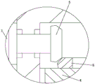
Fig. 3 is a schematic view of a partial enlarged structure of fig. 2.
Fig. 4 is a schematic view of a partial enlarged structure of fig. 2.
In the figure, 1 cauldron body, 2 feed inlet, 3 feeder hopper, 4 rotor plate, 5 bevel gears, 6 awl ring gears, 7 motors, 8 vertical stirring dwang, 9 drive gear, 10 gears, 11 ring gears, 12U formula support, 13 horizontal puddler, 14 fixed plate, 15 supporting legs, 16 discharge gates, 17 stop valve.
Detailed Description
Specific embodiments of the present utility model will be described in further detail below with reference to the accompanying drawings.
As shown in fig. 1-4, the chemical stirring kettle capable of being mixed in multiple directions comprises a kettle body 1, a feed inlet 2 and a feed hopper 3, wherein the feed inlet 2 is arranged on the side surface of the upper part of the kettle body 1, the feed hopper 3 is fixed on the side wall of the kettle body 1, the discharge end of the lower end of the feed hopper 3 is communicated with the feed inlet 2, the chemical stirring kettle also comprises a rotating plate 4, a bevel gear 5, a bevel gear ring 6, a motor 7 and a vertical stirring rotating rod 8, the rotating plate 4 is horizontally hinged on the inner wall of the kettle body 1 above the feed inlet 2 on the kettle body 1, the two vertical stirring rotating rods 8 are respectively hinged on the same offset radius taking the center of the rotating plate 4 as an origin, the bevel gear ring 6 is concentrically fixed on the rotating plate 4, the motor 7 is fixed on the side wall of the outer side of the kettle body 1, the shaft extension end of the motor 7 extends into the kettle body 1, the bevel gear 5 is arranged on the shaft extension end of the motor 7, and the bevel gear 5 is meshed with the bevel gear ring 6.
As a further embodiment, the stirring device further comprises a transmission gear 9, wherein two transmission gears 9 are meshed with each other and arranged in the rotating plate 4, and the two meshed transmission gears 9 are respectively fixed on the corresponding vertical stirring rotating rods 8.
As a further embodiment, the kettle further comprises a gear 10 and a gear ring 11, wherein the gear ring 11 and the rotating plate 4 are concentrically fixed on the top of the inner side of the kettle body 1, the gear 10 is fixedly arranged on the upper end of any one of the vertical stirring rotating rods 8, and the gear 10 is meshed with the gear ring 11.
As a further embodiment, the device further comprises a U-shaped bracket 12, wherein the lower ends of the U-shaped brackets 12 are respectively hinged with the corresponding vertical stirring rotating rods 8, and the upper ends of the U-shaped brackets 12 are respectively fixed below the rotating plate 4.
As a further embodiment, it further comprises a horizontal stirring rod 13, and two horizontal stirring rods 13 are respectively horizontally fixed on each vertical stirring rotating rod 8.
As a further embodiment, the kettle further comprises a fixing plate 14 and supporting legs 15, wherein the fixing plate 14 is fixedly arranged at the lower part of the outer side of the kettle body 1, and the upper ends of the supporting legs 15 are fixedly arranged on the fixing plate 14.
In the utility model, the kettle body 1 is horizontally supported by four supporting legs 15, the discharge port 16 is arranged at the bottom of the kettle body 1, and the discharge port 16 is provided with a stop valve 17.
When the stirring device works, raw materials enter the kettle body 1 through the feed hopper 3 and the feed inlet 2, the motor 7 drives the bevel gear 5 to rotate, the bevel gear 5 is meshed with the bevel gear ring 6, the rotating plate 4 rotates and drives the vertical stirring rotating rod 8 to revolve along the center of the rotating plate 4, the gear ring 11 is fixed, the vertical stirring rotating rod 8 revolves, the two transmission gears 9 are meshed, the gear 10 is meshed with the gear ring 11 to drive the two vertical stirring rotating rods 8 to rotate, and accordingly the horizontal stirring rod 13 is driven to rotate and revolve, and the efficient stirring effect is achieved.
The foregoing description is only of a preferred embodiment of the utility model and is not intended to limit the scope of the utility model.
Claims (6)
1. The utility model provides a chemical industry stirred tank that can multidirectional mix, includes the cauldron body, feed inlet and feeder hopper, the feed inlet sets up in cauldron body upper portion side, and the feeder hopper is fixed on cauldron body lateral wall, and the discharge end and the feed inlet of feeder hopper lower extreme are linked together, its characterized in that: still include rotor plate, bevel gear, awl ring gear, motor and vertical stirring dwang, the rotor plate level articulates on the cauldron body inner wall of cauldron body upper position on the feed inlet, and two vertical stirring dwang are articulated respectively on the same offset radius that uses the rotor plate center as the origin, awl ring gear is concentric to be fixed on the rotor plate, and the motor is fixed on cauldron body outside lateral wall, and the motor shaft stretches the end and stretches into in the cauldron, the bevel gear setting is on the motor shaft stretches the end, and bevel gear and awl ring gear mesh mutually.
2. The multi-directional mixing chemical stirring kettle according to claim 1, further comprising a transmission gear, wherein the two transmission gears are meshed with each other and arranged in the rotating plate, and the two meshed transmission gears are respectively fixed on the corresponding vertical stirring rotating rods.
3. The multidirectional mixing chemical stirring kettle according to claim 1, further comprising a gear and a gear ring, wherein the gear ring and the rotating plate are concentrically fixed on the top of the inner side of the kettle body, the gear is fixedly arranged on the upper end of any one of the vertical stirring rotating rods, and the gear is meshed with the gear ring.
4. The multidirectional mixing chemical stirring kettle according to claim 1, further comprising a U-shaped bracket, wherein the lower ends of the U-shaped brackets are respectively hinged with the corresponding vertical stirring rotating rods, and the upper ends of the U-shaped brackets are respectively fixed below the rotating plate.
5. The multi-directional mixing chemical stirring kettle according to claim 1, further comprising horizontal stirring rods, wherein a plurality of horizontal stirring rods are horizontally fixed on each vertical stirring rotating rod respectively.
6. The multidirectional mixed chemical stirring kettle according to claim 1, wherein: still include fixed plate and supporting leg, the fixed plate is fixed to be set up in cauldron outside lower part, the supporting leg upper end is fixed on the fixed plate.
Priority Applications (1)
| Application Number | Priority Date | Filing Date | Title |
|---|---|---|---|
| CN202223187915.7U CN218962383U (en) | 2022-11-30 | 2022-11-30 | Chemical industry stirred tank that can multidirectional mix |
Applications Claiming Priority (1)
| Application Number | Priority Date | Filing Date | Title |
|---|---|---|---|
| CN202223187915.7U CN218962383U (en) | 2022-11-30 | 2022-11-30 | Chemical industry stirred tank that can multidirectional mix |
Publications (1)
| Publication Number | Publication Date |
|---|---|
| CN218962383U true CN218962383U (en) | 2023-05-05 |
Family
ID=86155109
Family Applications (1)
| Application Number | Title | Priority Date | Filing Date |
|---|---|---|---|
| CN202223187915.7U Active CN218962383U (en) | 2022-11-30 | 2022-11-30 | Chemical industry stirred tank that can multidirectional mix |
Country Status (1)
| Country | Link |
|---|---|
| CN (1) | CN218962383U (en) |
-
2022
- 2022-11-30 CN CN202223187915.7U patent/CN218962383U/en active Active
Similar Documents
| Publication | Publication Date | Title |
|---|---|---|
| CN209735455U (en) | Production compounding agitating unit for carbon adsorbent | |
| CN208812304U (en) | A kind of efficient mixing machine | |
| CN211706616U (en) | Stirring device for processing compound food additive | |
| CN201510852U (en) | Planet motion type stirrer device | |
| CN108407092A (en) | A kind of efficient concrete central mix plant | |
| CN210114997U (en) | Stirred tank with high-efficient agitating unit | |
| CN211640724U (en) | Stirring mechanism of flame-retardant environment-friendly polymer sponge foaming machine | |
| CN209772004U (en) | Two-way mixer of fungus agent | |
| CN207822858U (en) | A kind of combined type gyratory agitation device | |
| CN218962383U (en) | Chemical industry stirred tank that can multidirectional mix | |
| CN210814812U (en) | High-speed blendor is used in production of nutrition powder | |
| CN211800389U (en) | Sea urchin can soup mixing arrangement | |
| CN211189967U (en) | Raw material mixing device is used in cosmetics production | |
| CN208927982U (en) | A kind of Chinese medicine agitating device | |
| CN214973175U (en) | Agitating unit is used in lignocellulose processing | |
| CN215233929U (en) | Homogenizing mixer for producing macroelement water-soluble fertilizer | |
| CN215877099U (en) | Chinese herbal medicine mixing arrangement of misce bene | |
| CN214111018U (en) | A raw material mixing equipment for production of electric power pipe | |
| CN212370178U (en) | Liquid circulation anti-deposition reaction kettle | |
| CN210522304U (en) | Spiral stirring device | |
| CN208247179U (en) | A kind of intelligent vacuum blender | |
| CN208878326U (en) | A kind of Blendling-device of feedstuffs | |
| CN203540423U (en) | Spiral stirrer for producing feed | |
| CN111546527A (en) | Raw material stirring device for modified plastic production | |
| CN215233930U (en) | Nitrogen potassium compound fertilizer mixer of stirring |
Legal Events
| Date | Code | Title | Description |
|---|---|---|---|
| GR01 | Patent grant | ||
| GR01 | Patent grant |