CN218933802U - Attached scaffold - Google Patents
Attached scaffold Download PDFInfo
- Publication number
- CN218933802U CN218933802U CN202223185939.9U CN202223185939U CN218933802U CN 218933802 U CN218933802 U CN 218933802U CN 202223185939 U CN202223185939 U CN 202223185939U CN 218933802 U CN218933802 U CN 218933802U
- Authority
- CN
- China
- Prior art keywords
- rod
- rods
- scaffold
- lifting
- clamping plate
- Prior art date
- Legal status (The legal status is an assumption and is not a legal conclusion. Google has not performed a legal analysis and makes no representation as to the accuracy of the status listed.)
- Active
Links
Images


Classifications
-
- Y—GENERAL TAGGING OF NEW TECHNOLOGICAL DEVELOPMENTS; GENERAL TAGGING OF CROSS-SECTIONAL TECHNOLOGIES SPANNING OVER SEVERAL SECTIONS OF THE IPC; TECHNICAL SUBJECTS COVERED BY FORMER USPC CROSS-REFERENCE ART COLLECTIONS [XRACs] AND DIGESTS
- Y02—TECHNOLOGIES OR APPLICATIONS FOR MITIGATION OR ADAPTATION AGAINST CLIMATE CHANGE
- Y02A—TECHNOLOGIES FOR ADAPTATION TO CLIMATE CHANGE
- Y02A40/00—Adaptation technologies in agriculture, forestry, livestock or agroalimentary production
- Y02A40/10—Adaptation technologies in agriculture, forestry, livestock or agroalimentary production in agriculture
- Y02A40/25—Greenhouse technology, e.g. cooling systems therefor
Landscapes
- Movable Scaffolding (AREA)
Abstract
The application discloses attached scaffold includes: a main body frame and a plurality of lifting assemblies, wherein the main body frame comprises an inner/outer vertical rod, a scaffold board, a protective net and a horizontal truss; the lifting assembly includes a rail and a lifting point truss. The main body frame is simple in structure and firm in connection; the guide rail is arranged into a spliced pre-installation structure, the guide rail can be reinforced without external force, and the connecting position has large span in the height direction and is firmly connected; the clamping plate assembly is arranged on the lifting point truss, so that the lifting point is arranged on the clamping plate assembly, the stress area of the lifting point is increased, and the lifting point is more stable in the lifting and descending processes.
Description
Technical Field
The utility model relates to the field of buildings, in particular to an attached scaffold.
Background
In the field of construction, scaffolds are often used, operators perform construction work by using the scaffolds, and the scaffolds can be lifted by using guide rails, so that the operators can conveniently perform work at a proper height.
The scaffold is usually assembled by the lifting devices such as a frame, a scaffold board, a guide rail, a lifting point truss and the like, and the conventional scaffold is inconvenient to assemble and has insufficient connection strength.
Disclosure of Invention
The utility model mainly aims to provide an attached scaffold which can solve the problems that the existing scaffold is inconvenient to assemble and the connection strength of a lifting device is insufficient.
To achieve the above object, the present utility model provides an attached scaffold comprising:
a main body frame and a plurality of lifting assemblies;
the main body frame includes:
the scaffold comprises a plurality of scaffold plates, a plurality of support plates and a plurality of support plates, wherein the scaffold plates are arranged at intervals up and down, and each scaffold plate at least comprises one scaffold plate;
the scaffold comprises a plurality of inner vertical rods and a plurality of outer vertical rods, wherein the inner vertical rods are arranged on one side edge of the scaffold board layer in the length direction at intervals, and the outer vertical rods are arranged on the other side edge of the scaffold board layer in the length direction at intervals;
a protective net is arranged between every two adjacent outer vertical rods;
the lower ends of the inner vertical rods and the lower ends of the outer vertical rods are respectively provided with a horizontal truss;
the length direction interval setting of a plurality of lifting assemblies in scaffold sheet layer, and every lifting assembly and the interior pole setting fixed connection of corresponding position, every lifting assembly all includes a plurality of guide rails that connect gradually, the guide rail includes:
the fixed rod is fixedly connected with the inner vertical rod;
The sliding rail comprises two guide rods which are arranged in parallel, and a plurality of anti-falling rods are arranged between the two guide rods;
the fixed rod is parallel to the sliding rail and is fixedly connected with the sliding rail;
the end parts of the two guide rods are respectively provided with a first connecting part, the end parts of the fixed rods are provided with first connecting holes, and the first connecting parts pass through the fixed rods at the end in the length direction of the fixed rods;
the other end of the sliding rail is provided with a second connecting part at the end part of the fixed rod, the end parts of the two guide rods are respectively provided with a second connecting hole, and the second connecting part passes over the guide rod at the end in the length direction of the fixed rod;
the first connecting part is used for extending into the second connecting hole of the adjacent guide rail, and the second connecting part is used for extending into the first connecting hole of the adjacent guide rail;
a plurality of transverse connecting rods are arranged between the fixed rod and the sliding rail at intervals in the length direction of the fixed rod, connecting pipe sleeves are sleeved on two transverse connecting rods positioned at two ends in the length direction of the sliding rail, and through holes are formed in the connecting pipe sleeves and the transverse connecting rods sleeved on the connecting pipe sleeves, and the connecting pipe sleeves are used for being connected with the connecting pipe sleeves on the adjacent sliding rails;
A plurality of oblique connecting rods are further arranged between the fixed rod and the sliding rail at intervals in the length direction of the fixed rod, one end of each oblique connecting rod is connected with one end of each transverse connecting rod connected with the anti-falling rod, the other end of each oblique connecting rod is connected with the fixed rod, and the oblique connecting rods, the transverse connecting rods and the fixed rods are enclosed to form a triangle;
each group of lifting assembly further comprises two lifting point trusses which are arranged at intervals up and down and are arranged opposite to each other, the two lifting point trusses are all arranged on the fixed rods of the corresponding guide rails, and each lifting point truss comprises:
the lifting point frame comprises an inner rod, an outer rod, a plurality of cross rods and a plurality of inclined rods, wherein the cross rods and the inclined rods are arranged between the inner rod and the outer rod;
the clamping plate assembly comprises a first clamping plate, a second clamping plate and a third clamping plate, the first clamping plate and the second clamping plate clamp the outer rod, the partial cross rod and the partial diagonal rod, the third clamping plate is arranged between the first clamping plate and the second clamping plate, and the third clamping plate is perpendicular to the first clamping plate and the second clamping plate;
An upper lifting point seat is arranged on the clamping plate component of the lifting point frame positioned above, and a lower lifting point seat is arranged on the clamping plate component of the lifting point frame positioned below; an electric hoist and a wall-attached hanging seat are arranged between the upper hanging point seat and the lower hanging point seat of each group of lifting components, an upper hook of an electric hoist chain is connected with the upper hanging point seat, a lower hook of the electric hoist chain is connected with the lower hanging point seat, and the chain is also connected with the wall-attached hanging seat;
each group of lifting components further comprises a plurality of wall attaching supports which are arranged at intervals up and down, and the wall attaching supports are matched with the sliding rail of the guide rail and the anti-falling rod.
In the embodiments of the present application,
the main body frame further comprises a bottom covering assembly, wherein the bottom covering assembly comprises an inner vertical rod connector, an outer vertical rod connector and a bottom covering cross rod connected with the bottom ends of the inner vertical rod connector and the outer vertical rod connector;
the bottom cross bar is positioned below the bottommost scaffold layer, the lower end of the inner vertical rod is inserted into the inner vertical rod connector, and the lower end of the outer vertical rod is inserted into the outer vertical rod connector.
In this application embodiment, the attached scaffold still includes the triangle bracing between the interior pole setting of mutual correspondence in the width direction of scaffold sheet layer and the outer pole setting, all be equipped with in the below of every layer of scaffold sheet layer the triangle bracing.
In this embodiment of the present application, the triangular diagonal brace includes: a first rod, a second rod and a third rod which enclose to form a right triangle, wherein the first rod is along the vertical direction, the second rod is along the horizontal direction, and the third rod is inclined upwards;
the first rod is fixedly connected with the inner vertical rod;
and the inclined upward end part of the third rod is provided with a connecting sheet, and the connecting sheet is connected to the outer vertical rod after being overlapped with the outer side wall of the scaffold board layer corresponding to the triangular diagonal bracing.
In this embodiment of the present application, the first connecting portion is kept away from the one end of guide arm is equipped with the guiding portion, the diameter of guiding portion is kept away from the one end of guide arm to the guide arm direction increases gradually.
In this embodiment of the present application, the connection sleeve is a square tube.
In an embodiment of the present application, the cleat assembly further comprises:
the reinforcing plates are provided with perforations, the inner rod is provided with a plurality of mounting holes, and the reinforcing plates are arranged on the inner rod and are coaxial with the mounting holes respectively.
In this application embodiment, attach wall hanging seat includes:
the wall-attached backboard is used for being installed on a wall body;
the two wall-attached side plates are arranged on the plate surface of the wall-attached back plate, which is away from the wall body, at intervals;
The cotter pin is arranged between the two wall-attached side plates;
the chain of the electric hoist is fixed on the split pin.
The attached scaffold provided by the embodiment of the application has the advantages that the main body frame structure is high in strength, and the assembly modes of the inner upright rod, the outer upright rod, the scaffold plate and other components are simple; the lifting assembly comprises a guide rail and a lifting point truss, for the guide rail, a first connecting part is arranged on a guide rod at one end of the guide rail, a second connecting part is arranged on a fixing rod at the other end of the guide rail, the first connecting part passes over the fixing rod at the same end, the second connecting part passes over the guide rod at the same end, and the first connecting part and the second connecting part form an inserting structure, so that when the guide rail is combined, the first connecting part of the lower guide rod can extend upwards into a first connecting hole of the upper guide rod, the second connecting part of the upper fixing rod can extend downwards into a second connecting hole of the lower fixing rod, a pre-installation structure is formed, the upper guide rail and the lower guide rail can be aligned without other external force, and the next reinforcing action is facilitated; in addition, the combination position of two adjacent guide rails in this application is great in the direction of height span, and the combination position is fixed relatively, can't remove on the horizontal plane, and not all on the coplanar like each joint in the prior art, it is more firm to connect in contrast. For the hoisting point truss, this application embodiment, through set up the splint subassembly on the hoisting point truss, no matter use this hoisting point truss as lower hoisting point truss, still use as last hoisting point truss, the hoisting point seat all can be installed on the splint subassembly, and the first splint of splint subassembly and second splint all have great area, not only are convenient for install the hoisting point seat, have great contact surface with the hoisting point seat moreover, can be with the force that the hoisting point seat received, on the even dispersion is to whole hoisting point truss, have higher steadiness.
Drawings
In order to more clearly illustrate the embodiments of the present utility model or the technical solutions in the prior art, the drawings that are required in the embodiments or the description of the prior art will be briefly described, and it is obvious that the drawings in the following description are only some embodiments of the present utility model, and other drawings may be obtained according to the structures shown in these drawings without inventive effort for a person skilled in the art.
Fig. 1 is a schematic structural view of a main body frame of an attached scaffold according to an embodiment of the present utility model;
FIG. 2 is a schematic view of a bottom assembly of an attached scaffold according to an embodiment of the present utility model;
FIG. 3 is a schematic view illustrating a structure of a bottom covering assembly of an attached scaffold according to an embodiment of the present utility model connected to a scaffold board;
fig. 4 is a schematic structural view of a horizontal truss of an attached scaffold according to an embodiment of the present utility model;
fig. 5 is a schematic structural view of a triangle diagonal bracing installation position of an attached scaffold according to an embodiment of the present utility model;
fig. 6 is a schematic structural view of a main body frame of an attached scaffold according to another embodiment of the present utility model;
Fig. 7 is a schematic structural view of an attached scaffold corner according to an embodiment of the present utility model;
fig. 8 is a schematic structural view of an attached scaffold corner according to another embodiment of the present utility model;
fig. 9 is a schematic structural view of a guide rail of an attached scaffold according to an embodiment of the present utility model;
FIG. 10 is a schematic view of the structure of the upper end of a guide rail according to an embodiment of the present utility model;
FIG. 11 is a schematic view of a lower end of a guide rail according to an embodiment of the present utility model;
FIG. 12 is a schematic view of a structure of a connecting position of two adjacent guide rails according to an embodiment of the present utility model;
FIG. 13 is a schematic view of a wall-attached support according to an embodiment of the present utility model;
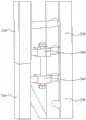
FIG. 14 is a schematic view of a construction of a lifting point frame of a lifting point truss according to an embodiment of the present utility model;
FIG. 15 is a schematic view of the structure of an upper and lower lifting truss according to another embodiment of the present utility model;
FIG. 16 is a schematic view of a cleat assembly according to an embodiment of the present utility model;
FIG. 17 is a schematic view illustrating a structure of an upper suspension point seat according to an embodiment of the present utility model;
FIG. 18 is a schematic view illustrating a structure of a lower suspension point seat according to an embodiment of the present utility model;
fig. 19 is a schematic structural view of a wall-attached hanging seat according to an embodiment of the present utility model.
Reference numerals illustrate: 100-main body frame, 110-scaffold board, 120-inner pole, 130-outer pole, 140-inner pole joint, 141-first fixing part, 142-first joint part, 150-outer pole joint, 151-second fixing part, 152-second joint part, 153-bottom rail, 160-horizontal truss, 170-triangle diagonal bracing, 171-first pole, 172-second pole, 173-third pole, 174-connecting piece, 180-protective net, 190-horizontal connecting plate, 200-guide rail, 210-fixing pole, 211-first connecting hole, 212-second connecting part, 220-guide rod, 221-first connecting part, 222-second connecting hole, 223-guide part, 230-falling preventing pole, 240-transverse connecting rod, 250-diagonal connecting rod, 260-connecting sleeve, 300-wall mount, 310-anti-roll device, 320-sliding channel, 400-lifting point frame, 410-inner rod, 420-outer rod, 430-first cross rod, 431-second cross rod, 440-first diagonal rod, 441-second diagonal rod, 442-third diagonal rod, 450-cleat assembly, 451-first cleat, 452-second cleat, 453-third cleat, 454-reinforcing plate, 460-upper lifting point seat, 461-upper lifting point back plate, 462-upper lifting point side plate, 463-upper lifting point plate, 464-upper lifting point pin sleeve, 465-first reinforcing plate, 470-lower lifting point seat, 471-lower lifting point back plate, 472-lower lifting point side plate, 473-second reinforcing plate, 474-third reinforcing plate, 500-wall-attached hanging seat, 510-wall-attached back plate, 520-wall-attached side plate, 530-cotter pins 530, 540-circular notch.
The achievement of the objects, functional features and advantages of the present utility model will be further described with reference to the accompanying drawings, in conjunction with the embodiments.
Detailed Description
The following description of the embodiments of the present utility model will be made clearly and fully with reference to the accompanying drawings, in which it is evident that the embodiments described are only some, but not all embodiments of the utility model. All other embodiments, which can be made by those skilled in the art based on the embodiments of the utility model without making any inventive effort, are intended to be within the scope of the utility model.
It should be noted that, if directional indications (such as up, down, left, right, front, and rear … …) are included in the embodiments of the present utility model, the directional indications are merely used to explain the relative positional relationship, movement conditions, etc. between the components in a specific posture (as shown in the drawings), and if the specific posture is changed, the directional indications are correspondingly changed.
In addition, if there is a description of "first", "second", etc. in the embodiments of the present utility model, the description of "first", "second", etc. is for descriptive purposes only and is not to be construed as indicating or implying a relative importance or implicitly indicating the number of technical features indicated. Thus, a feature defining "a first" or "a second" may explicitly or implicitly include at least one such feature. In addition, the technical solutions of the embodiments may be combined with each other, but it is necessary to base that the technical solutions can be realized by those skilled in the art, and when the technical solutions are contradictory or cannot be realized, the combination of the technical solutions should be considered to be absent and not within the scope of protection claimed in the present utility model.
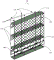
The present utility model proposes an attached scaffold, in an embodiment of the present utility model, as shown in fig. 1, the attached scaffold includes: a main body frame 100 and a plurality of lifting assemblies;
the main body frame 100 includes:
a plurality of scaffold plies, the plurality of scaffold plies being spaced apart from one another, each scaffold ply comprising at least one scaffold plate 110;
the scaffold comprises a plurality of inner vertical rods 120 and a plurality of outer vertical rods 130, wherein the plurality of inner vertical rods 120 are arranged on one side edge of the scaffold board layer in the length direction at intervals, and the plurality of outer vertical rods 130 are arranged on the other side edge of the scaffold board layer in the length direction at intervals;
a protective net 180 is arranged between two adjacent outer uprights 130;
the lower ends of the inner uprights 120 and the lower ends of the outer uprights 130 are respectively provided with a horizontal truss 160;
the length direction interval setting of a plurality of lifting assemblies in scaffold layer, and every lifting assembly and interior pole setting 120 fixed connection of corresponding position, every lifting assembly all includes a plurality of guide rails 200 that connect gradually, guide rail 200 includes:
a fixing rod 210 fixedly connected to the inner upright 120;
the sliding rail comprises two guide rods 220 which are arranged in parallel, and a plurality of anti-falling rods 230 are arranged between the two guide rods 220;
The fixing rod 210 is parallel to the sliding rail, and the fixing rod 210 is fixedly connected with the sliding rail;
at one end of the sliding rail, the ends of the two guide rods 220 are respectively provided with a first connecting portion 221, the end of the fixing rod 210 is provided with a first connecting hole 211, and the first connecting portion 221 passes over the fixing rod 210 at the end along the length direction of the fixing rod 210;
at the other end of the sliding rail, the end of the fixing rod 210 is provided with a second connecting portion 212, the end of the two guide rods 220 are provided with second connecting holes 222, and the second connecting portion 212 passes over the guide rod 220 at the end in the length direction of the fixing rod 210;
the first connecting portion 221 is configured to extend into the second connecting hole 222 of the adjacent rail 200, and the second connecting portion 212 is configured to extend into the first connecting hole 211 of the adjacent rail 200;
in the length direction of the fixing rod 210, a plurality of transverse connecting rods 240 are arranged between the fixing rod 210 and the sliding rail at intervals, in the length direction of the sliding rail 200, connecting pipe sleeves 260 are sleeved on two transverse connecting rods 240 positioned at two ends, and through holes are formed in the connecting pipe sleeves 260 and the transverse connecting rods 240 sleeved on the connecting pipe sleeves 260, and the connecting pipe sleeves 260 are used for being connected with the connecting pipe sleeves 260 on the adjacent sliding rail 200;
In the length direction of the fixing rod 210, a plurality of oblique connecting rods 250 are further disposed between the fixing rod 210 and the sliding rail at intervals, one end of each oblique connecting rod 250 is connected with one end of each transverse connecting rod 240 connected with the anti-falling rod 230, the other end of each oblique connecting rod 250 is connected with the fixing rod 210, and the oblique connecting rods 250, the transverse connecting rods 240 and the fixing rods 210 enclose to form a triangle;
each group of lifting assemblies further comprises two lifting point trusses which are arranged at intervals up and down and are arranged opposite to each other, the two lifting point trusses are arranged on the fixing rods 210 of the corresponding guide rails 200, and each lifting point truss comprises:
a hanging point frame 400, wherein the hanging point frame 400 comprises an inner rod 410 and an outer rod 420, and a plurality of cross rods and a plurality of diagonal rods arranged between the inner rod 410 and the outer rod 420, and the inner rod 410 is arranged on the fixed rod 210;
a clamping plate assembly 450, wherein the clamping plate assembly 450 comprises a first clamping plate 451, a second clamping plate 452 and a third clamping plate 453, the first clamping plate 451 and the second clamping plate 452 clamp the outer rod 420, a part of the cross rod and a part of the diagonal rod, the third clamping plate 453 is arranged between the first clamping plate 451 and the second clamping plate 452, and the third clamping plate 453 is perpendicular to the first clamping plate 451 and the second clamping plate 452;
The upper hanging point seat 460 is arranged on the clamping plate assembly 450 of the hanging point frame 400 positioned above, and the lower hanging point seat 470 is arranged on the clamping plate assembly 450 of the hanging point frame 400 positioned below;
an electric hoist and a wall-attached hanging seat 500 are arranged between the upper hanging point seat 460 and the lower hanging point seat 470 of each group of lifting components, an upper hook of an electric hoist chain is connected with the upper hanging point seat 460, a lower hook of the electric hoist chain is connected with the lower hanging point seat 470, and the chain is also connected with the wall-attached hanging seat 500;
each set of lifting assemblies further comprises a plurality of wall-attaching supports 300 arranged at intervals up and down, and the wall-attaching supports 300 are matched with the sliding rails of the guide rail 200 and the anti-falling rods 230.
Each scaffold board layer is formed by splicing a plurality of scaffold boards 110, threaded holes are formed in two ends of the scaffold boards 110 in the length direction, and the adjacent scaffold boards 110 are connected through threads, so that the scaffold boards are convenient to detach. The specific layer number of the scaffold board layer is set according to actual needs. The assembly starts from the lowest scaffold board layer, threaded holes are also formed in the inner side wall and the outer side wall of the scaffold board 110, the inner side is the side close to the building, the outer side is the side far away from the building, the inner upright pole 120 is in threaded connection with the inner side wall of the scaffold board 110, the outer upright pole 130 is in threaded connection with the outer side wall of the scaffold board 110, and the inner upright pole 120 and the outer upright pole 130 are in one-to-one correspondence in the width direction of the scaffold board 110.
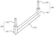
In the embodiment of the present application, the main body frame 100 further includes a bottom bracket assembly including an inner pole connector 140 and an outer pole connector 150, and a bottom bracket 153 connected to the bottom ends of the inner pole connector 140 and the outer pole connector 150;
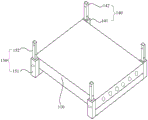
the bottom rail 153 is located below the bottommost scaffold board layer 110, the lower end of the inner upright 120 is inserted into the inner upright connector 140, and the lower end of the outer upright 130 is inserted into the outer upright connector 130. As shown in fig. 1, 2 and 3 and 4, fig. 2 is a schematic structural diagram of the bottom component, and fig. 3 is a schematic structural diagram of the bottom component connected to the bottom scaffold board layer 110, wherein the outer pole joint 150 includes a second fixing portion 151 and a second joint portion 152, the inner pole joint 140 includes a first fixing portion 141 and a first joint portion 142, the second joint portion 152 and the first joint portion 142 have the same structure, and are used for inserting the outer pole 130 or the inner pole 120, and the second joint portion 152 and the first joint portion 142 are provided with perforations, so that after the outer pole 130 or the inner pole 120 is inserted, the outer pole can be further reinforced by bolts. The first fixing portion 141 and the first fixing portion 141 are provided with threaded holes, when in installation, the bottom foot scaffold board layer 110 is arranged on the bottom-holding cross bar 153, the inner side wall and the outer side wall of the scaffold board layer 110 are in threaded connection with the first fixing portion 141 and the second fixing portion 152, so that the bottom-holding cross bar 153 can play a role in bearing the scaffold board layer 110, and the bottom-holding scaffold board layer 110 can be fixed from the inner side and the outer side, so that the connection is firmer.
In addition, the head and tail of each inner upright 120 and each outer upright 130 are respectively arranged to be mutually sleeved, so that the inner uprights 120 can be sleeved up and down, and the outer uprights 130 can be sleeved up and down according to the requirements, so that the required height can be achieved.
As shown in fig. 1 and 4, the outer side of the horizontal truss 160 is a substantially rectangular frame structure, and vertical and oblique connecting rods are provided inside the horizontal truss 160, so that a frame structure having a plurality of triangles inside the frame structure is formed, and the stability is high. By providing the horizontal truss 160 in the horizontal direction of the scaffold, thereby connecting each inner pole 120 and each outer pole in the horizontal direction as one body, the overall stability of the scaffold is increased.
As shown in fig. 1, a protection net 180 is disposed between adjacent outer uprights 130, the protection net 180 is in a grid shape, and the protection net 180 can protect staff located on the scaffold board 110 from falling from the scaffold board 110. In addition, for ease of understanding the construction of the scaffold of the present application, the lowermost scaffold sheet of fig. 1 does not show the protection net 180, but does not represent that the lowermost scaffold sheet in the embodiment of the present application does not have the protection net 180.
As shown in fig. 4, in the present embodiment, the first rod 171 and the third rod 173 of the triangular diagonal brace 170 are square rods, the second rod 172 is a circular rod, and the scaffold board 110 of each layer is in threaded connection with the outer upright 130 through the through hole on the outer side wall, so that the connecting piece 174 may be disposed at the upper end of the third rod 173, and the connecting piece 174 may be disposed with the through hole, and the side wall of the scaffold board 110 is disposed between the connecting piece 174 and the outer upright 130 during connection, and reinforced by bolts, so that not only installation space is saved, but also the three are integrally connected, and the first rod 171 is fixed on the inner upright 120 through threads, so that the triangular diagonal brace 170 can support the inner side and the outer side of the scaffold, and the overall connection strength is more stable. In addition, as shown in fig. 1, the inner and outer uprights 120 and 130 are in one-to-one correspondence in the inner and outer directions, so that the triangular diagonal braces 170 may be provided at positions of the inner and outer uprights 120 and 130 under each scaffold layer, further increasing the overall connection strength.
As shown in fig. 6, in the application embodiment, in order to adapt to the corner position of the building, the scaffold may also have an "L" structure, where the installation manner of the scaffold with the "L" structure is the same as that of the scaffold shown in fig. 1, and the installation positions and the installation manners of the inner upright rod connector 140, the inner upright rod 120, the outer upright rod connector 150, the outer upright rod 130, the triangular diagonal brace 170, and the protection net 180 are the same as those of the scaffold in fig. 1, and are not repeated herein. In addition, in the scaffold of the "L" -shaped structure, the lower ends of the inner and outer uprights 120 and 130 after the corners are also provided with horizontal trusses 160, and the horizontal trusses 160 at both sides of the corners may be connected using angle steel or horizontal connection plates 190 to ensure the overall connection strength at both sides of the corners. For example, as shown in fig. 7, when the corner S is a male corner, the horizontal trusses 160 on both sides of the corner may be connected by angle steel; when the corner is an inside corner, horizontal trusses 160 on both sides of the corner may be connected using horizontal connection plates 190, as shown in fig. 8.
As shown in fig. 1, in the embodiment of the present application, the scaffold further includes a plurality of lifting assemblies, where the number of lifting assemblies is based on the length of the scaffold in the horizontal direction, and the lifting assemblies are disposed between the scaffold and the building, for example, in the scaffold shown in fig. 1, one lifting assembly may be disposed at each of the positions of four inner uprights 120, or one lifting assembly may be disposed at each of the first and fourth inner uprights 120 from left to right.
As shown in fig. 9, 10, 11 and 12, in this application, each lifting assembly is assembled up and down by a plurality of guide rails 200, wherein, for each guide rail 200, the fixing rod 210 and the two guide rods 220 approximately form a triangular frame structure, the fixing rod 210 and the two guide rods 220 are all arranged in parallel, and the fixing rod 210 is located on the symmetrical plane of the two guide rods 220, so that the cross section of the whole guide rail 200 is isosceles triangle, that is, the distance between the fixing rod 210 and the two guide rods 220 is the same, and then the stress of each position of the whole guide rail 200 is relatively uniform. In addition, a plurality of anti-falling rods 230 are arranged between the two guide rods 220, the anti-falling rods 230 are arranged at intervals, the anti-falling rods 230 are perpendicular to the guide rods 220, each anti-falling rod 230 and the two guide rods 220 form a sliding rail, and the sliding rail is fixedly connected with the fixing rod 210, so that the sliding rail and the fixing rod 210 form a whole. When the sliding rail is installed, the fixing rod 210 is connected to the inner side surface of the inner upright 120 in a threaded manner, so that the plane of the sliding rail is oriented to the inner side surface after installation.
In addition, as shown in fig. 13, a plurality of wall-attached supports 300 are further disposed between each lifting assembly and the building from top to bottom, the wall-attached supports 300 are fixed on the building, two sliding channels 320 are disposed on each wall-attached support 300, the two sliding channels 320 are adapted to the two guide rods 220 of the guide rail 200, an anti-tilting device 310 is further disposed on the wall-attached support 300, the anti-tilting device 310 is adapted to the anti-falling rod 230 between the two guide rods 220, and when the guide rail 200 is lifted or lowered, the sliding channels 320 of the wall-attached supports 300 can limit the guide rods 220, so that the guide rods 220 can only vertically upwards or vertically downwards, and the anti-tilting device 310 can prevent the guide rail 200 from being lowered at a high speed.
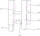
With continued reference to fig. 9, 10, 11, and 12, in the embodiment of the present application, the first connection portion 221 extends upward from the upper end of the guide rod 220 and passes over the end of the upper end of the fixing rod 210, and the fixing rod 210 is hollow, so that the fixing rod 210 forms the first connection hole 211 at the end of the upper end. The guide rods 220 are also hollow structures, and the two guide rods 220 respectively form second connection holes 222 at the lower ends of the guide rails 200. The end of the lower end of the fixing rod 210 is provided with a second connection part 212, and the second connection part 212 extends downward from the lower end of the fixing rod 210 and passes over the ends of the two guide rods 220 at the lower ends. When the upper and lower rails 200 are combined, the two first connection parts 221 of the lower rail 200 extend into the second connection holes 222 of the two guide rods 220 of the upper rail 200, and the second connection part 212 of the upper rail 200 extends into the first connection holes 211 of the fixing rod 210 of the lower rail 200, that is, the two first connection parts 221 extend upward, and the second connection part 212 extends downward, so that an inserting structure can be formed by using the first connection parts 221, the second connection parts 212, the first connection holes 211 and the second connection holes 222, and the upper and lower rails 200 form a pre-installation structure, and the upper and lower rails 200 can form a relatively fixed structure without external force, so that further reinforcement can be performed only based on the pre-installation structure. In the structure of the guide rail 200 in the prior art, an upper connecting portion and a lower connecting portion are disposed at two ends of the guide rod 220 and the fixing rod 210, and the heights of the connecting portions of the guide rail 200 at the same end (the connecting portions of the fixing rod 210 and the end portion of the guide rod 220 at the same end) are the same, that is, three connecting portions at the same end are on the same plane, when the guide rail 200 is installed, the corresponding upper connecting portions and the corresponding lower connecting portions of the guide rail 200 are required to be aligned, at this time, the upper and lower guide rails 200 do not perform any reinforcement step, only the end portions of the guide rod 220 and the fixing rod 210 are contacted based on the upper connecting portions and the lower connecting portions, and the spliced pre-installation structure is not formed like the present application, if no external force supports, the upper and lower guide rails 200 are easy to shake, so that the upper and lower guide rails 200 are required to be kept relatively fixed under the action of external force, and then the upper connecting portions and the lower connecting portions corresponding to each other can be rotationally connected. Moreover, after the upper and lower guide rails 200 in the prior art are combined, the combining positions of the two fixing rods 210 and the combining positions of the four guide rods 220 are all located on the same plane, and the combining mode is surface contact, but after the upper and lower guide rails 200 in the embodiment of the application are combined, the combining positions are not limited to be on the same plane, and the combining mode of the application is plug-in contact, i.e. the first connecting part 221 extends upwards into the guide rod 220 located above, while the second connecting part 212 extends downwards into the fixing rod 210 located below, and the whole combining position has larger upper and lower spans, is relatively fixed, cannot move on the horizontal plane, so that shaking is not easy to occur, and the connection is more firm.
As shown in fig. 9 and 10, in this embodiment, in the length direction of the fixing rod 210, a plurality of diagonal connecting rods 250 are further disposed between the fixing rod 210 and the sliding rail at intervals, one end of each diagonal connecting rod 250 is connected with one end of each transverse connecting rod 240 connected with the anti-falling rod 230, the other end of each diagonal connecting rod 250 is connected with the fixing rod 210, and the diagonal connecting rods 250, the transverse connecting rods 240 and the fixing rod 210 enclose to form a triangle. The diagonal connecting bars 250, the transverse connecting bars 240, and the fixing bars 210 form a triangle structure, thereby having high stability and being capable of improving the bearing capacity of the scaffold lifting rail 200. In addition, as shown in fig. 9, in the embodiment of the present application, not all the adjacent two transverse connection rods 240 are provided with the oblique connection rods 250, and a specific number of the oblique connection rods 250 may be calculated according to the load capacity required by the scaffold lifting rail 200, and after the specific number is obtained, the scaffold lifting rail 200 may be uniformly arranged in the length direction of the scaffold lifting rail 200. In addition, the oblique directions of the oblique connecting rods 250 may be the same or different, for example, the oblique directions of two adjacent oblique connecting rods 250 may be different.
As shown in fig. 10, 11 and 12, in the embodiment of the present application, the connection sleeves 260 are disposed on the transverse connection rods 240 at the uppermost end and the lowermost end of each guide rail 200, the transverse connection rods 240 are round tubes, the connection sleeves 260 are square tubes, the connection sleeves 260 are sleeved on the transverse connection rods 240 at the uppermost end and the lowermost end of each guide rail 200, and corresponding through holes are disposed on the transverse connection rods 240 and the connection sleeves 260. When the upper and lower guide rails 200 are combined, the connecting sleeve 260 at the lowermost end of the upper guide rail 200 can be connected with the connecting sleeve 260 at the uppermost end of the lower guide rail 200 by using the stud, so that the combination firmness of the upper and lower guide rails 200 can be improved, the connecting sleeve 260 is a square tube, and has a larger contact area with the stud, so that the stud can be ensured to have higher fastening degree, and loosening is avoided.
With continued reference to fig. 9, 10, 11, and 12, in another embodiment of the present application, corresponding through holes may be further provided on the first connection portion 221, the second connection portion 212, the fixing rod 210, and the guide rod 220, so that after the first connection portion 221 extends into the first connection hole 211 of the guide rod 220, the first connection portion may be further reinforced by shaft pins, bolts, or the like in cooperation with the through holes. Similarly, after the second connection portion 212 extends into the second connection hole 222 of the fixing rod 210, it may be further reinforced by a shaft pin, a bolt, or the like in cooperation with the perforation.
As shown in fig. 10, in the embodiment of the present application, the guide portion 223 is generally in a truncated cone shape, and the diameter of the guide portion 223 extending from the head portion to the guide rod 220 is changed from thin to thick, so that the guide portion 223 can perform a guiding function during assembly, and is convenient to extend into the first connecting hole 211, and convenient to install.
In this embodiment, each lifting assembly is further provided with an upper and a lower lifting point truss, which are both mounted on the side walls of the fixing rod 210 of the guide rail 200 for each lifting assembly. The lifting point truss provided by the embodiment of the application not only can be used as an upper lifting point truss, but also can be used as a lower lifting point truss, and after the two lifting point trusses are arranged at proper positions, the wall-attached lifting seat 500 and the electric hoist are arranged between the two lifting point trusses, so that a lifting scaffold lifting structure can be formed.
As shown in fig. 14, in the embodiment of the present application, the outer rod 420 and the inner rod 410 are square rods, and the outer rod 420, the inner rod 410, and the cross rod and the diagonal rod therebetween can form the hanging point frame 400 having a plurality of triangles, so that the hanging point frame 400 has high stability. The inner pole 410 is long in length, and the inner pole 410 is fixedly installed at an upper position of the fixing pole 210 when the hanging point truss is used as an upper hanging point truss, and the inner pole 410 is fixedly installed at a lower position of the fixing pole 210 when the hanging point truss is used as a lower hanging point truss. The length of the outer pole 420 is shorter than that of the inner pole 410, and a certain distance is provided between the outer pole 420 and the inner pole 410, and the two poles are arranged in parallel.
In an embodiment of the present application, the plurality of crossbars includes: a first cross bar 430 and a second cross bar 431, wherein the first cross bar 430 and the second cross bar 431 are arranged between the inner bar 410 and the outer bar 420 at intervals, one end of each of the first cross bar 430 and the second cross bar 431 is connected with the inner bar 410, the other end is connected with the outer bar 420, and each of the first cross bar 430 and the second cross bar 431 is perpendicular to the inner bar 410;
the plurality of diagonal rods includes:
a first diagonal member 440, wherein one end of the first diagonal member 440 is connected to a connection point between the first cross member 430 and the outer bar 420, and the other end is connected to an end portion of the inner bar 410 located at one end of the first cross member 430;
a second diagonal member 441, where the second diagonal member 441 is disposed between the first cross member 430 and the second cross member 431, and one end of the second diagonal member 441 is connected to a connection point between the second cross member 431 and the inner member 410, and the other end is connected to a connection point between the first cross member 430 and the outer member 420;
and a third inclined rod 442, wherein one end of the third inclined rod 442 is connected to the connection point of the second cross rod 431 and the outer rod 420, and the other end is connected to the end of the inner rod 410 located at one end of the second cross rod 431.
As shown in fig. 15 and 16, in the embodiment of the present application, the first clamping plate 451 and the second clamping plate 452 are each flat plate-shaped, and the two plate surfaces of the first clamping plate 451 and the second clamping plate 452 facing each other clamp the hanging point frame 400 from both sides. The widths of the first diagonal member 440, the second diagonal member 441, the third diagonal member 442, the first cross bar 430, the second cross bar 431, and the outer bar 420 (the projections of the diagonal members, the cross bars, and the outer bar 420 on the inner upright 120) may be set to be the same and smaller than the inner bar 410, so that both sides (left and right sides in fig. 15) of the first diagonal member 440, the second diagonal member 441, the third diagonal member 442, the first cross bar 430, the second cross bar 431, and the outer bar 420 are all located on the same plane, and at this time, the first clamping plate 451 and the second clamping plate 452 may be disposed at both sides of the connection positions of the first diagonal member 440, the first cross bar 430, and the second diagonal member 441, and the first clamping plate 451 and the second clamping plate 452 may cover all of the first cross bar 430 at both sides, and cover part of the first diagonal member 440 and part of the second diagonal member 441, and cover part of the outer bar 420, and the first clamping plate 451 and the second clamping plate 452 are connected with the first diagonal member 440, the second diagonal member 441, the third diagonal member 442, and the cross bar 420, such as welding, and the connection positions of the two clamping plates 420 are firmly secured. In addition, since the width of the first cross bar 430 is smaller than that of the inner bar 410, two steps are formed at the positions of the inner bar 410 at both sides of the first cross bar 430, so that the first clamping plate 451 and the second clamping plate 452 can be provided with appropriate lengths such that one side thereof abuts against the steps and is fixedly coupled, such as welded, with the inner bar 410, thereby further enhancing the coupling strength. The third splint 453 is disposed at a gap between the first splint 451 and the second splint 452, and is perpendicular to the first splint 451 and the second splint 452, in this embodiment, the third splint 453 may be welded between the first splint 451 and the second splint 452 in a welding manner, and the third splint 453 may be disposed to support and strengthen the first splint 451 and the second splint 452.
As shown in fig. 15, for this arrangement of the present embodiment, on the one hand, the lifting point truss is used as a lower lifting point truss or as an upper lifting point truss, and the lifting point base can be mounted on the clamping plate assembly 450, and the first clamping plate 451 and the second clamping plate 452 of the clamping plate assembly 450 have larger areas, so that not only is the lifting point base convenient to mount, but also the lifting point base has a larger contact surface, so that the force applied by the lifting point base can be evenly dispersed to the whole lifting point truss, and the stability is higher.
On the other hand, if the lifting point truss is used as the lifting point truss, the lifting point seat 460 is located at the upper position of the lifting point truss, and the lifting point truss mainly plays a role of fixing and pulling the electric hoist upwards at this moment, that is, the scaffold to be lifted located below can apply a downward pulling force to the outer rod 420 of the lifting point truss, and at this moment, the second diagonal rod 441 and the third diagonal rod 442 are both inclined, so that an upward supporting force can be provided for the outer rod 420, and thus the outer rod 420 of the lifting point truss can be prevented from being deformed under the action of the downward pulling force. If the lifting truss is used as the lower lifting truss, the lower lifting seat 470 is located at a position below the lifting truss, and the lifting truss mainly plays a role in driving the scaffold to rise or fall at this time, that is, the outer rod 420 of the lifting truss can be pulled upwards, and at this time, the second inclined rod 441 and the third inclined rod 442 are inclined downwards, so that the outer rod 420 can be supported downwards, and the outer rod 420 is prevented from deforming under the action of the upward pulling force, which results in deformation of the lifting truss.
As shown in fig. 15 and 16, in the embodiment of the present application, the clamping plate assembly 450 further includes a plurality of reinforcing plates 454, the reinforcing plates 454 are provided with perforations, the inner rod 410 is provided with a plurality of mounting holes, and the plurality of reinforcing plates 454 are disposed on the inner rod 410 and are coaxial with the plurality of mounting holes, respectively. The inner rod 410 of the hanging point truss is used for being mounted on the fixing rod 210 of the guide rail 200, so that the inner rod 410 is provided with a plurality of mounting holes, the inner rod 410 is fixed on the fixing rod 210 through bolts, after long-time use, the inner rod 410 is easy to wear at the positions of the mounting holes, and the inner rod 410 is damaged due to repeated tightening and loosening of the bolts, so that the reinforcing plates 454 are arranged at the positions of the mounting holes, the bolts are prevented from being directly contacted with the inner rod 410, the thickness of the periphery of the mounting holes of the inner rod 410 is increased, and the wear resistance is good.
As shown in fig. 17, in the embodiment of the present application, the lifting point seat 460 includes: an upper hanging point back plate 461, the upper hanging point back plate 461 being disposed on the cleat assembly 450; two upper hanging point side plates 462, wherein the two upper hanging point side plates 462 are arranged on the surface of the upper hanging point back plate 461 away from the clamping plate assembly 450 at intervals, and the two upper hanging point side plates 462 are perpendicular to the upper hanging point back plate 461; two upper hanging point plates 463, wherein the two upper hanging point plates 463 are arranged between the two upper hanging point side plates 462 at intervals, and the two upper hanging point plates 463 are perpendicular to the two upper hanging point side plates 462; and an upper lifting point pin sleeve 464, wherein the upper lifting point pin sleeve 464 is arranged between the two upper lifting point plates 463 and is positioned at one end of the two upper lifting point plates 463 away from the upper lifting point side plates 462. The upper lifting point plate 461 is approximately flat, and can have a larger contact area with the first clamping plate 451 or the second clamping plate 452, the upper lifting point side plate 462 is perpendicular to the upper lifting point plate 461, and can bear larger traction force, the upper lifting point plate 463 is perpendicular to the two upper lifting point side plates 462, so that the two upper lifting point side plates 462 have a limiting effect on the two upper lifting point plates 463, electric hoist arranged between the two upper lifting point plates 463 is prevented from swaying back and forth, and a pin bush arranged at the lower end of the upper lifting point plate 463 can provide a connecting point for an upper hook of an electric hoist chain.
As shown in fig. 17, in the embodiment of the present application, the lifting point seat 460 further includes: two first reinforcing plates 465, two the first reinforcing plates 465 are located respectively the outside of two the upper hanging point side plates 462, the first reinforcing plates 465 are connected respectively with the upper hanging point back plate 461 and the upper hanging point side plates 462. Wherein, first reinforcing plate 465 is fixedly connected, such as welded, with upper hanging point back plate 461 and upper hanging point side plate 462, and forms a triangular supporting effect, which can provide supporting force from the left and right sides to the middle, and can prevent upper hanging point side plate 462 from deforming to the left and right sides.
As shown in fig. 16, in this embodiment, the first clamping plate 451 and the second clamping plate 452 are provided with a plurality of corresponding through holes, the upper lifting point back plate 461 is provided with through holes matching with the through holes on the clamping plate assembly 450, and when the device is installed, the upper lifting point seat 460 can be fixed on the clamping plate assembly 450 by using stud bolts through the through holes. For example, the upper hanging point back plate 461 is attached to the first clamping plate 451 or the second clamping plate 452, and then the upper hanging point back plate 461, the first clamping plate 451, and the second clamping plate 452 are passed through by using stud bolts, and then tightening and reinforcing are performed.
As shown in fig. 18, in the embodiment of the present application, the lower hanging point seat 470 includes: a lower suspension point back plate 471, said lower suspension point back plate 471 being disposed over said cleat assembly 450; two lower suspension point side plates 472, wherein the two lower suspension point side plates 472 are arranged on the surface of the lower suspension point back plate 471 deviating from the clamping plate assembly 450 at intervals, and the two lower suspension point side plates 472 are perpendicular to the upper suspension point back plate 461; and a lower suspension point pin sleeve arranged between the two lower suspension point side plates 472. The lower lifting point back plate 471 is approximately flat, and can have a larger contact area with the first clamping plate 451 or the second clamping plate 452, the lower lifting point side plate 472 is perpendicular to the lower lifting point back plate 471, can bear larger traction force, and the lower lifting point pin sleeve provides a connection point for a lower hook of the electric hoist chain.
As shown in fig. 18, in the embodiment of the present application, the lower hanging point seat 470 further includes: two second reinforcing plates 473, the two second reinforcing plates 473 being located outside the two lower suspension point side plates 472, respectively, the second reinforcing plates 473 being connected to the lower suspension point back plate 471 and the lower suspension point side plates 472, respectively; the third reinforcing plate 474 is disposed between the two lower suspension point side plates 472 and connected to the lower suspension point back plate 471. Wherein, the two second reinforcing plates 473 are perpendicular to the lower suspension point back plate 471 and the lower suspension point side plate 472, respectively, and the second reinforcing plates 473 are fixedly connected, such as welded, with the lower suspension point back plate 471 and the lower suspension point side plate 472, so that the two second reinforcing plates 473 can support and reinforce the two lower suspension point side plates 472 from both sides, and the third reinforcing plates 474 can also support and reinforce the two lower suspension point side plates 472 from the middle. In addition, the connection between the lower hanging point seat 470 and the hanging point truss in the embodiment of the present application is the same as that of the upper hanging point seat 460, and is not described in detail herein.
As shown in fig. 19, in the embodiment of the present application, the wall-attached hanging seat 500 includes: a wall-attached back plate 510 for mounting on a wall; the two wall-attached side plates 520 are arranged on the surface of the wall-attached back plate 510, which is away from the wall body, at intervals; the cotter pin 530 is disposed between the two wall-attached side plates 520. Wherein, attach wall backplate 510 on can be fixed on the wall body through wearing the wall screw rod, two attach wall curb plate 520 parallel arrangement, and all with attach wall backplate 510 perpendicularly, be provided with circular breach 540 on attaching the wall curb plate 520, be convenient for install attach the wall screw rod, attach wall mount pad 500 whole setting between last hoisting point truss and lower hoisting point truss, electric hoist can adopt circulating electric hoist, the last couple of its chain is connected on last hoisting point round pin cover 464, the lower couple of chain is connected on lower hoisting point round pin cover, the terminal point that is located the chain in the centre is connected on the cotter 530 of attaching wall mount pad 500, thereby realize electric hoist's exempting from to remove through circulating chain.
The attached scaffold provided by the embodiment of the application has higher structural strength of the main body frame 100, and the assembly modes of the inner upright rod 120, the outer upright rod 130, the scaffold plate 110 and other components are simple; the lifting assembly comprises a guide rail 200 and a lifting point truss, for the guide rail 200, a first connecting part 221 is arranged on a guide rod 220 at one end of the guide rail 200, a second connecting part 212 is arranged on a fixing rod 210 at the other end, the first connecting part 221 passes over the fixing rod 210 at the same end, the second connecting part 212 passes over the guide rod 220 at the same end, the first connecting part 221 and the second connecting part 212 form an inserting structure, so that when the guide rail 200 is combined, the first connecting part 221 at the lower part can extend upwards into a first connecting hole 211 of the guide rod 220 at the upper part, the second connecting part 212 of the fixing rod 210 at the upper part can extend downwards into a second connecting hole 222 of the fixing rod 210 at the lower part, a pre-installation structure is formed, the upper guide rail 200 and the lower guide rail 200 can be aligned without other external force, and the next reinforcing action is facilitated; in addition, in the present application, the span of the combining position of two adjacent guide rails 200 in the height direction is larger, the combining position is relatively fixed, and cannot move on the horizontal plane, unlike the prior art, in which each combining point is on the same plane, and the connection is firmer. For the hanging point truss, this application embodiment, through set up splint subassembly 450 on the hanging point truss, no matter use this hanging point truss as lower hanging point truss, still use as last hanging point truss, the hanging point seat all can install on splint subassembly 450, and the first splint 451 of splint subassembly 450 and second splint 452 all have great area, not only are convenient for install the hanging point seat, have great contact surface with the hanging point seat moreover, can be with the force that the hanging point seat received, on the even dispersion to whole hanging point truss, have higher steadiness.
The foregoing are all preferred embodiments of the present application, and are not intended to limit the scope of the present application in any way, therefore: all equivalent changes in structure, shape and principle of this application should be covered in the protection scope of this application.
Claims (8)
1. An attached scaffold comprising: a main body frame and a plurality of lifting assemblies;
the main body frame includes:
the scaffold comprises a plurality of scaffold plates, a plurality of support plates and a plurality of support plates, wherein the scaffold plates are arranged at intervals up and down, and each scaffold plate at least comprises one scaffold plate;
the scaffold comprises a plurality of inner vertical rods and a plurality of outer vertical rods, wherein the inner vertical rods are arranged on one side edge of the scaffold board layer in the length direction at intervals, and the outer vertical rods are arranged on the other side edge of the scaffold board layer in the length direction at intervals;
a protective net is arranged between every two adjacent outer vertical rods;
the lower ends of the inner vertical rods and the lower ends of the outer vertical rods are respectively provided with a horizontal truss;
the length direction interval setting of a plurality of lifting assemblies in scaffold sheet layer, and every lifting assembly and the interior pole setting fixed connection of corresponding position, every lifting assembly all includes a plurality of guide rails that connect gradually, the guide rail includes:
the fixed rod is fixedly connected with the inner vertical rod;
The sliding rail comprises two guide rods which are arranged in parallel, and a plurality of anti-falling rods are arranged between the two guide rods;
the fixed rod is parallel to the sliding rail and is fixedly connected with the sliding rail;
the end parts of the two guide rods are respectively provided with a first connecting part, the end parts of the fixed rods are provided with first connecting holes, and the first connecting parts pass through the fixed rods at the end in the length direction of the fixed rods;
the other end of the sliding rail is provided with a second connecting part at the end part of the fixed rod, the end parts of the two guide rods are respectively provided with a second connecting hole, and the second connecting part passes over the guide rod at the end in the length direction of the fixed rod;
the first connecting part is used for extending into the second connecting hole of the adjacent guide rail, and the second connecting part is used for extending into the first connecting hole of the adjacent guide rail;
a plurality of transverse connecting rods are arranged between the fixed rod and the sliding rail at intervals in the length direction of the fixed rod, connecting pipe sleeves are sleeved on two transverse connecting rods positioned at two ends in the length direction of the sliding rail, and through holes are formed in the connecting pipe sleeves and the transverse connecting rods sleeved on the connecting pipe sleeves, and the connecting pipe sleeves are used for being connected with the connecting pipe sleeves on the adjacent sliding rails;
A plurality of oblique connecting rods are further arranged between the fixed rod and the sliding rail at intervals in the length direction of the fixed rod, one end of each oblique connecting rod is connected with one end of each transverse connecting rod connected with the anti-falling rod, the other end of each oblique connecting rod is connected with the fixed rod, and the oblique connecting rods, the transverse connecting rods and the fixed rods are enclosed to form a triangle;
each group of lifting assembly further comprises two lifting point trusses which are arranged at intervals up and down and are arranged opposite to each other, the two lifting point trusses are all arranged on the fixed rods of the corresponding guide rails, and each lifting point truss comprises:
the lifting point frame comprises an inner rod, an outer rod, a plurality of cross rods and a plurality of inclined rods, wherein the cross rods and the inclined rods are arranged between the inner rod and the outer rod;
the clamping plate assembly comprises a first clamping plate, a second clamping plate and a third clamping plate, the first clamping plate and the second clamping plate clamp the outer rod, the partial cross rod and the partial diagonal rod, the third clamping plate is arranged between the first clamping plate and the second clamping plate, and the third clamping plate is perpendicular to the first clamping plate and the second clamping plate;
An upper lifting point seat is arranged on the clamping plate component of the lifting point frame positioned above, and a lower lifting point seat is arranged on the clamping plate component of the lifting point frame positioned below; an electric hoist and a wall-attached hanging seat are arranged between the upper hanging point seat and the lower hanging point seat of each group of lifting components, an upper hook of an electric hoist chain is connected with the upper hanging point seat, a lower hook of the electric hoist chain is connected with the lower hanging point seat, and the chain is also connected with the wall-attached hanging seat;
each group of lifting components further comprises a plurality of wall attaching supports which are arranged at intervals up and down, and the wall attaching supports are matched with the sliding rail of the guide rail and the anti-falling rod.
2. The attached scaffold of claim 1, wherein the main body frame further comprises a bottom pocket assembly comprising an inner pole joint and an outer pole joint, and a bottom pocket rail connected to the inner pole joint bottom end and the outer pole joint bottom end;
the bottom cross bar is positioned below the bottommost scaffold layer, the lower end of the inner vertical rod is inserted into the inner vertical rod connector, and the lower end of the outer vertical rod is inserted into the outer vertical rod connector.
3. The attached scaffold of claim 1, further comprising a triangular diagonal brace disposed below each scaffold ply between inner and outer uprights of the scaffold plies that correspond to each other in a width direction thereof.
4. An attached scaffold as in claim 3, wherein the triangular diagonal brace comprises: a first rod, a second rod and a third rod which enclose to form a right triangle, wherein the first rod is along the vertical direction, the second rod is along the horizontal direction, and the third rod is inclined upwards;
the first rod is fixedly connected with the inner vertical rod;
and the inclined upward end part of the third rod is provided with a connecting sheet, and the connecting sheet is connected to the outer vertical rod after being overlapped with the outer side wall of the scaffold board layer corresponding to the triangular diagonal bracing.
5. The attached scaffold of claim 1, wherein the end of the first connection portion remote from the guide bar is provided with a guide portion having a diameter that gradually increases from the end remote from the guide bar toward the guide bar.
6. The attached scaffold of claim 1, wherein the connecting tube sleeve is a square tube.
7. The attached scaffold of claim 1, wherein the cleat assembly further comprises:
the reinforcing plates are provided with perforations, the inner rod is provided with a plurality of mounting holes, and the reinforcing plates are arranged on the inner rod and are coaxial with the mounting holes respectively.
8. The attached scaffold of claim 1, wherein the wall mount comprises:
the wall-attached backboard is used for being installed on a wall body;
the two wall-attached side plates are arranged on the plate surface of the wall-attached back plate, which is away from the wall body, at intervals;
the cotter pin is arranged between the two wall-attached side plates;
the chain of the electric hoist is fixed on the split pin.
Priority Applications (1)
| Application Number | Priority Date | Filing Date | Title |
|---|---|---|---|
| CN202223185939.9U CN218933802U (en) | 2022-11-29 | 2022-11-29 | Attached scaffold |
Applications Claiming Priority (1)
| Application Number | Priority Date | Filing Date | Title |
|---|---|---|---|
| CN202223185939.9U CN218933802U (en) | 2022-11-29 | 2022-11-29 | Attached scaffold |
Publications (1)
| Publication Number | Publication Date |
|---|---|
| CN218933802U true CN218933802U (en) | 2023-04-28 |
Family
ID=86094208
Family Applications (1)
| Application Number | Title | Priority Date | Filing Date |
|---|---|---|---|
| CN202223185939.9U Active CN218933802U (en) | 2022-11-29 | 2022-11-29 | Attached scaffold |
Country Status (1)
| Country | Link |
|---|---|
| CN (1) | CN218933802U (en) |
-
2022
- 2022-11-29 CN CN202223185939.9U patent/CN218933802U/en active Active
Similar Documents
| Publication | Publication Date | Title |
|---|---|---|
| CN214498341U (en) | Plate supporting mechanism for attached lifting scaffold | |
| CN218933802U (en) | Attached scaffold | |
| KR100609726B1 (en) | Guide device for a climbing typed construction frame | |
| CN219011881U (en) | Scaffold lifting point truss | |
| KR200413590Y1 (en) | Scaffold and construction structure thereof | |
| CN215889318U (en) | Wall-attached support mounting device for attached lifting scaffold | |
| CN214739791U (en) | Truss type cantilever beam combined structure for climbing frame | |
| WO2023019319A1 (en) | An extendable needle davit assembly | |
| CN113202281A (en) | Building templates operation platform | |
| CN211920714U (en) | Support system of pull-up and pull-down type external hanging self-climbing tower crane | |
| CN218933791U (en) | Scaffold lifting guide rail | |
| CN111332964A (en) | Steel reinforced column wall-attached device and construction method thereof | |
| CN213927417U (en) | Attached lifting scaffold | |
| CN214885646U (en) | Material platform drawknot connecting piece | |
| CN213597448U (en) | Upright rod connecting support and upright rod connecting structure | |
| KR200388764Y1 (en) | coupling board for tower crane wall fixing | |
| CN218668470U (en) | Wall-attached seat for attached lifting scaffold | |
| CN215167879U (en) | Reinforcing system for climbing frame | |
| CN215631489U (en) | Building templates operation platform | |
| CN219528341U (en) | Construction platform | |
| CN213015330U (en) | Lower hanging seat for climbing frame lifting | |
| CN218934632U (en) | Mobile maintenance platform for fan conductor rail | |
| CN217353639U (en) | Climbing frame is with hanging a truss | |
| CN213418450U (en) | Hanging flower basket mounting on roof pergola roof beam | |
| CN215107161U (en) | A down-bracing formula scaffold frame for assembly type structure outer wall |
Legal Events
| Date | Code | Title | Description |
|---|---|---|---|
| GR01 | Patent grant | ||
| GR01 | Patent grant |