CN218928362U - An inner tube vulcanization sealing device - Google Patents
An inner tube vulcanization sealing device Download PDFInfo
- Publication number
- CN218928362U CN218928362U CN202221948301.3U CN202221948301U CN218928362U CN 218928362 U CN218928362 U CN 218928362U CN 202221948301 U CN202221948301 U CN 202221948301U CN 218928362 U CN218928362 U CN 218928362U
- Authority
- CN
- China
- Prior art keywords
- steam pipe
- ring
- inner tube
- vulcanization
- valve
- Prior art date
- Legal status (The legal status is an assumption and is not a legal conclusion. Google has not performed a legal analysis and makes no representation as to the accuracy of the status listed.)
- Active
Links
Images

Landscapes
- Heating, Cooling, Or Curing Plastics Or The Like In General (AREA)
Abstract
Description
技术领域technical field
本实用新型涉及一种密封装置,具体地,是一种内胎硫化密封装置。The utility model relates to a sealing device, in particular to an inner tire vulcanization sealing device.
背景技术Background technique
内胎硫化是内胎生产最后一步工序,内胎硫化内部是通过充入蒸汽以保证硫化的基本要素——温度和压力,硫化完毕排出内胎内的蒸汽,否则会出现开模爆胎现象。如图1所示,现有技术的充气装置使用内密封,包括气门嘴1、密封垫2、气芯3和蒸汽管4。充气装置设置有密封垫2,可以防止漏气。内胎硫化后蒸汽的排出需要气门嘴1连接气缸来实现。在合模时,模具拨叉对气门嘴1施加压力,实现气门嘴1与对嘴之间的密封。现有技术中常用的气门嘴1的气芯3内径,即蒸汽管4内径只有2.5mm,严重制约充气及排气速度,硫化生产效率低。因此在合模时,经常存在气芯3与充气装置的对嘴对接不顺,气门嘴盘边缘部会在气门嘴1偏歪方向的反方向受力,导致受力处打褶。为确保气芯与对嘴的完全正确地对接,需要减慢合模的速度。这会严重影响内胎生产效率,还会因为合模慢导致内胎下模先受热,内胎靠近下模一侧变软变形,导致胎身横折,而严重影响内胎质量。Inner tube vulcanization is the last step of inner tube production. Inner tube vulcanization is filled with steam to ensure the basic elements of vulcanization—temperature and pressure. After vulcanization, the steam in the inner tube will be discharged, otherwise mold opening and tire blowout will occur. As shown in FIG. 1 , an inflatable device in the prior art uses an internal seal, including a
因此,如何通过改进内胎硫化密封装置,使用静密封,以较低的成本,增大蒸汽管内径,提高内胎硫化充气速度和蒸汽的排出速度,提高内胎质量,并解决内胎硫化过程中气门嘴偏歪问题,是目前有待解决的技术问题。Therefore, how to improve the inner tube vulcanization sealing device, use static seals, increase the inner diameter of the steam pipe at a lower cost, increase the vulcanization inflation speed of the inner tube and the discharge speed of the steam, improve the quality of the inner tube, and solve the valve deviation during the vulcanization process of the inner tube. The crooked problem is a technical problem to be solved at present.
在专利文献(中国授权公告号CN 203863887 U)所记载的内胎硫化充气装置中,通过加装对接部,提高内胎硫化充气速度和蒸汽的排出速度,并解决气门嘴偏歪问题。但是其仍然通过气芯密封,没有改变现有技术中蒸汽管的密封方式,没有对充气装置进行重新设计、使用静密封代替原来的平面密封来取消气芯,还没有与内胎硫化充气和蒸汽的排出相符合的气门嘴。因此,该装置的生产成本比本申请高,且维修成本也要高于本申请。In the inner tube vulcanization and inflation device described in the patent document (China Authorized Notification No. CN 203863887 U), the vulcanization and inflation speed of the inner tube and the discharge speed of steam are improved by adding a butt joint, and the problem of the deflection of the valve is solved. However, it is still sealed by the air core, without changing the sealing method of the steam pipe in the prior art, without redesigning the inflation device, using a static seal instead of the original flat seal to cancel the air core, and not yet compatible with the inner tube vulcanization, inflation and steam Exhaust the corresponding valve. Therefore, the production cost of this device is higher than the present application, and the maintenance cost is also higher than the present application.
实用新型内容Utility model content
本实用新型的目的是提供一种内胎硫化密封装置,用于通过改进内胎硫化密封装置,增大蒸汽管内径,提高内胎硫化充气速度和蒸汽的排出速度,并解决气门嘴偏歪问题,所述装置包括气门嘴、O型圈和蒸汽管;The purpose of this utility model is to provide an inner tire vulcanization sealing device, which is used to improve the inner tire vulcanization sealing device, increase the inner diameter of the steam pipe, improve the inner tire vulcanization inflation speed and steam discharge speed, and solve the problem of the deflection of the valve mouth. The unit includes valves, O-rings and steam pipes;
所述O型圈位于蒸汽管内壁的凹槽中;The O-ring is located in the groove on the inner wall of the steam pipe;
所述O型圈为矩形环或锥面环;The O-ring is a rectangular ring or a tapered ring;
所述O型圈至少有2个;There are at least two O-rings;
所述O型圈使蒸汽管的轴向形成密封。The O-ring forms a seal in the axial direction of the steam pipe.
所述矩形所述O型圈通过O型圈两侧压力差,使蒸汽管的轴向形成密封。The rectangular O-ring forms a seal in the axial direction of the steam pipe through the pressure difference on both sides of the O-ring.
优选地,所述锥面环形成迷宫式漏气通道;Preferably, the conical ring forms a labyrinth leak channel;
所述锥面环减轻对蒸汽管的凹槽的冲击。The conical ring dampens the impact on the groove of the steam pipe.
优选地,所述O型圈至少有2个;Preferably, there are at least two O-rings;
优选地,所述蒸汽管在安装轴端设有引入角。Preferably, the steam pipe is provided with an introduction angle at the installation shaft end.
因此,通过本申请的技术方案,可以实现对内胎硫化密封装置的改进,增大蒸汽管内径,提高内胎硫化充气速度和蒸汽的排出速度,并解决气门嘴偏歪问题,还使操作不熟练的新工人也可以立马上手操作,提高了内胎生产效率,减少了企业生产成本。Therefore, through the technical proposal of the present application, it is possible to improve the vulcanization and sealing device of the inner tube, increase the inner diameter of the steam pipe, increase the vulcanization and inflation speed of the inner tube and the discharge speed of the steam, and solve the problem of the deflection of the valve, and also make unskilled operators New workers can also operate immediately, which improves the production efficiency of the inner tube and reduces the production cost of the enterprise.
附图说明Description of drawings
为了更清楚地说明本申请实施例中的技术方案,下面将对实施例描述中所需要使用的附图作简单地介绍,显而易见地,下面描述中的附图仅仅是本申请的一些实施例,对于本领域技术人员来讲,在不付出创造性劳动的前提下,还可以根据这些附图获得其他的附图。In order to more clearly illustrate the technical solutions in the embodiments of the present application, the drawings that need to be used in the description of the embodiments will be briefly introduced below. Obviously, the drawings in the following description are only some embodiments of the present application. For those skilled in the art, other drawings can also be obtained based on these drawings without any creative effort.
图1示出了现有技术充气装置示意图;Fig. 1 shows the schematic diagram of prior art inflator;
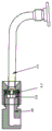
图2示出了本实用新型密封装置示意图;Fig. 2 shows the schematic diagram of the utility model sealing device;
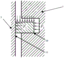
图3示出了本实用新型矩形环受力分析图;Fig. 3 shows the stress analysis diagram of the rectangular ring of the present utility model;
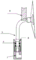
图4示出了本实用新型锥面环示意图。Fig. 4 shows a schematic diagram of the taper ring of the present invention.
具体实施方式Detailed ways
下面将结合本申请实施例中的附图,对本申请实施例中的技术方案进行清楚、完整地描述,显然,所描述的实施例仅仅是本申请一部分实施例,而不是全部的实施例。基于本申请中的实施例,本领域普通技术人员在没有做出创造性劳动前提下所获得的所有其他实施例,都属于本申请保护的范围。The following will clearly and completely describe the technical solutions in the embodiments of the application with reference to the drawings in the embodiments of the application. Apparently, the described embodiments are only some of the embodiments of the application, not all of them. Based on the embodiments in this application, all other embodiments obtained by persons of ordinary skill in the art without making creative efforts belong to the scope of protection of this application.
本申请实施例提出了一种内胎硫化密封装置,用于通过改进内胎硫化密封装置,增大蒸汽管内径,提高内胎硫化充气速度和蒸汽的排出速度,并解决气门嘴偏歪问题,还使操作不熟练的新工人也可以立马上手操作。The embodiment of this application proposes an inner tube vulcanization sealing device, which is used to improve the inner tube vulcanization sealing device, increase the inner diameter of the steam pipe, increase the vulcanization inflation speed of the inner tube and the discharge speed of steam, and solve the problem of the deflection of the valve, and also make the operation Even new and unskilled workers can get started right away.
如图2所示,所述装置是对现有技术中内胎硫化充气装置进行重新设计的装置,包括O型圈6和蒸汽管7。As shown in FIG. 2 , the device is a redesigned device for the inner tube vulcanization and inflation device in the prior art, including an O-
所述O型圈6位于蒸汽管7内壁的凹槽中,该凹槽位于安装轴端8的正下方的位置。The O-
所述O型圈6至少有2个,最好有2到3个。There are at least 2 O-
所述O型圈为矩形环,其结构简单、制造方便,可以大规模生产以降低生产成本。The O-ring is a rectangular ring with a simple structure and convenient manufacture, and can be mass-produced to reduce production costs.
所述蒸汽管7在安装轴端8设有引入角,方便O型圈的安装和更换。The
内胎硫化前,模具拨叉9对气门嘴5的一端施加压力,使气门嘴5的另一端被O型圈夹紧,形成气门嘴5和蒸汽管7间的密封。Before the inner tube is vulcanized, the
因此,所述O型圈为静密封,所述蒸汽管7可以和气门嘴5的内径相当。在本实施例中其具体为4.2mm,O型圈内径按一级修理尺寸规定为4.45mm,以后每更换维修一次,O型圈内径按修理尺寸规定加大0.25mm。Therefore, the O-ring is a static seal, and the
内胎硫化过程中,气门嘴5与汽缸连接,蒸汽管7固定于硫化模具中。During the vulcanization process of the inner tube, the
所述O型圈通过O型圈两侧压力差,使蒸汽管的径向形成密封,具体为:The O-ring forms a seal in the radial direction of the steam pipe through the pressure difference on both sides of the O-ring, specifically:
内胎硫化过程中,O型圈受力分析,如图3所示,F2为O型圈两侧压力差形成的高压气体的压力,F1为O型圈对气门嘴5的作用力,第一密封面11为气门嘴5和蒸汽管7间的密封面,即蒸汽管7的径向密封面,第二密封面12为蒸汽管7在O型圈上下轴向的密封面。通过F1和F2的作用,使第一密封面11和第二密封面12密封,形成蒸汽管7的轴向密封。During the vulcanization process of the inner tube, the force analysis of the O-ring, as shown in Figure 3, F2 is the pressure of the high-pressure gas formed by the pressure difference on both sides of the O-ring, F1 is the force of the O-ring on the
在本申请另一个实施例中,所述O型圈为锥面环,减轻对蒸汽管的凹槽的冲击,如图4所示,具体为:In another embodiment of the present application, the O-ring is a tapered ring to reduce the impact on the groove of the steam pipe, as shown in Figure 4, specifically:
所述锥面环6的断面呈锥形,其外圆工作面上加工一个0.5度到1.5度的锥面,减小了环与蒸汽管7的接触面,提高了表面接触压力,减轻对蒸汽管7的凹槽的冲击。The cross-section of the
内胎硫化过程中,所述锥面环6的锥面的油楔作用,可以使硫化后产生的少量硫化物和杂质从油膜上通过,减小对蒸汽管7的凹槽的冲击和磨损。During the vulcanization process of the inner tube, the oil wedge effect of the conical surface of the
因此,本申请装置的蒸汽管内径4.2mm,远大于现有技术中蒸汽管内径2.5mm,提高了内胎硫化充气速度和蒸汽的排出速度,还使操作不熟练的新工人也可以立马上手操作,提高生产效率50%以上。Therefore, the internal diameter of the steam pipe of the device of the present application is 4.2 mm, which is much larger than the internal diameter of the steam pipe of 2.5 mm in the prior art, which improves the vulcanization and inflation speed of the inner tube and the discharge speed of the steam, and also enables new workers who are not skilled in operation to operate immediately. Improve production efficiency by more than 50%.
因此,本申请装置的蒸汽管内径可以与气门嘴内径一致,解决了现有技术中因为其内径不一致、对接不顺,导致气门嘴盘边缘部会在气门嘴偏歪方向的反方向受力,导致受力处打褶的技术问题。Therefore, the inner diameter of the steam pipe of the device of the present application can be consistent with the inner diameter of the valve, which solves the problem that in the prior art, because of its inconsistent inner diameter and uneven butt joint, the edge of the valve plate will be stressed in the opposite direction of the deflection direction of the valve, resulting in The technical problem of pleating at the stressed place.
上面结合附图对本实用新型实施例作了详细说明,但是本实用新型不限于上述实施例,在所述技术领域普通技术人员所具备的知识范围内,还可以在不脱离本实用新型宗旨的前提下做出各种变化。The above embodiments of the utility model have been described in detail in conjunction with the accompanying drawings, but the utility model is not limited to the above-mentioned embodiments. Make various changes below.
Claims (4)
Priority Applications (1)
| Application Number | Priority Date | Filing Date | Title |
|---|---|---|---|
| CN202221948301.3U CN218928362U (en) | 2022-07-26 | 2022-07-26 | An inner tube vulcanization sealing device |
Applications Claiming Priority (1)
| Application Number | Priority Date | Filing Date | Title |
|---|---|---|---|
| CN202221948301.3U CN218928362U (en) | 2022-07-26 | 2022-07-26 | An inner tube vulcanization sealing device |
Publications (1)
| Publication Number | Publication Date |
|---|---|
| CN218928362U true CN218928362U (en) | 2023-04-28 |
Family
ID=86067598
Family Applications (1)
| Application Number | Title | Priority Date | Filing Date |
|---|---|---|---|
| CN202221948301.3U Active CN218928362U (en) | 2022-07-26 | 2022-07-26 | An inner tube vulcanization sealing device |
Country Status (1)
| Country | Link |
|---|---|
| CN (1) | CN218928362U (en) |
Cited By (1)
| Publication number | Priority date | Publication date | Assignee | Title |
|---|---|---|---|---|
| CN115891239A (en) * | 2022-12-07 | 2023-04-04 | 山东玲珑轮胎股份有限公司 | Inner tube vulcanization sealing device and method thereof |
-
2022
- 2022-07-26 CN CN202221948301.3U patent/CN218928362U/en active Active
Cited By (2)
| Publication number | Priority date | Publication date | Assignee | Title |
|---|---|---|---|---|
| CN115891239A (en) * | 2022-12-07 | 2023-04-04 | 山东玲珑轮胎股份有限公司 | Inner tube vulcanization sealing device and method thereof |
| CN115891239B (en) * | 2022-12-07 | 2025-06-13 | 山东玲珑轮胎股份有限公司 | Inner tube vulcanization sealing device and method thereof |
Similar Documents
| Publication | Publication Date | Title |
|---|---|---|
| CN109141763B (en) | Auxiliary sealing rubber ring air tightness inspection tool in aviation graphite seal | |
| CN116518093A (en) | A zero leakage butterfly valve | |
| CN115891239A (en) | Inner tube vulcanization sealing device and method thereof | |
| CN216843164U (en) | A kind of sealing protection device for butterfly valve plate | |
| CN106764034A (en) | A kind of valve output shaft seal structure | |
| CN209877613U (en) | Dynamic sealing device of rotary kiln | |
| CN203863887U (en) | Inner tube vulcanization inflation device | |
| CN220242487U (en) | Tire repairing and tire pressure repairing device | |
| CN111396184A (en) | Novel engine exhaust pipe sealing structure | |
| CN104742284A (en) | Tyre vulcanizer central mechanism and tyre vulcanizer | |
| CN217301001U (en) | A hydrostatic isolation seal assembly for double bellows turbo pump | |
| CN206802310U (en) | A kind of waste rubber cracking device end part of driving shaft sealing structure | |
| CN212177855U (en) | Shaft end sealing device of rotating equipment | |
| CN206681963U (en) | Suitable for the reciprocating pump packing seal structure of high-temperature medium | |
| CN201086374Y (en) | Sealing mechanism of B type vulcanizing machine center mechanism | |
| CN205763164U (en) | A kind of metal bellows shaped by fluid pressure is with sealing structure | |
| CN213744926U (en) | Novel sealed zero-leakage poppet valve | |
| CN111876535B (en) | Method for adjusting sealing valve of charging bucket at top of blast furnace | |
| CN211260014U (en) | Pipeline leakage point plugging device | |
| CN222231955U (en) | Sealing head for airtight leakage test and check of engine | |
| CN218992352U (en) | Sealing ring with profiled dynamic pressure groove | |
| CN223814355U (en) | Anti-dust filler sealing device of reciprocating compressor | |
| CN220957374U (en) | PCCP pipeline maintenance frock | |
| CN222811268U (en) | A liquefied gas pressure reducing valve core | |
| CN211343045U (en) | Automobile engine valve oil seal |
Legal Events
| Date | Code | Title | Description |
|---|---|---|---|
| GR01 | Patent grant | ||
| GR01 | Patent grant |