CN218907292U - Barrows with wheels - Google Patents
Barrows with wheels Download PDFInfo
- Publication number
- CN218907292U CN218907292U CN202222874340.XU CN202222874340U CN218907292U CN 218907292 U CN218907292 U CN 218907292U CN 202222874340 U CN202222874340 U CN 202222874340U CN 218907292 U CN218907292 U CN 218907292U
- Authority
- CN
- China
- Prior art keywords
- assembly
- cart
- frame
- handle
- folded
- Prior art date
- Legal status (The legal status is an assumption and is not a legal conclusion. Google has not performed a legal analysis and makes no representation as to the accuracy of the status listed.)
- Active
Links
Images


Landscapes
- Handcart (AREA)
Abstract
The utility model discloses a handcart, which has an unfolding state and a folding state, and comprises a frame with a containing space and a handle assembly, wherein the frame comprises a bottom support assembly horizontally arranged, a connecting assembly arranged at the corner position of the frame, and a side baffle assembly arranged between two adjacent connecting assemblies and surrounding the bottom support assembly to form the containing space; the handle assembly comprises a lower handle rod and an upper handle rod which are connected in a rotating mode, the lower handle rod is connected to the frame in a rotating mode, the side baffle assemblies are folded and mutually close in a folding mode, a storage space is formed at the top of the frame, and the upper handle rod is placed in the storage space in a rotating mode. The handle component does not exceed the frame in the height direction in the folded state, so that the whole is convenient to store, pack and transport; and when the device is unfolded and used, the device meets the length and size requirements of users.
Description
Technical Field
The utility model relates to a household carrier, in particular to a handcart convenient to store.
Background
A cart, such as a vehicle for loading items or children outdoors, includes a frame, wheels, and a handle.
For example, patent document CN 217532890U discloses a folding cart, in which a push handle is located above a height of a frame in a folded state, which is not advantageous for storage, packaging, and the like.
In order not to exceed the frame, the height of the pushing handle is shortened, so that the pushing handle does not exceed the frame in the height direction in the folded state, but the pushing handle is insufficient in length, and the pulling of a user is not facilitated. Or the push handle is arranged to be of a telescopic structure, but the operation of contracting the push handle by one step is added when the push handle is folded, but the problem of sliding blockage exists due to the longer telescopic length.
Disclosure of Invention
The application provides a handcart, satisfies the operation requirement and does benefit to and accomodates and pack the transportation.
The present application provides a cart having an expanded state and a collapsed state, the cart comprising
The frame is provided with a containing space and comprises a bottom support assembly horizontally arranged, a connecting assembly arranged at the corner position of the frame, and a side baffle assembly arranged between two adjacent connecting assemblies and encircling the bottom support assembly to form the containing space;
the handle assembly comprises a lower handle rod and an upper handle rod which are connected in a rotating mode, the lower handle rod is connected with the frame in a rotating mode, the side baffle assemblies are folded and mutually close in a folding mode, a storage space is formed at the top of the frame, and the upper handle rod is placed in the storage space in a rotating mode.
The following provides several alternatives, but not as additional limitations to the above-described overall scheme, and only further additions or preferences, each of which may be individually combined for the above-described overall scheme, or may be combined among multiple alternatives, without technical or logical contradictions.
Optionally, the side baffle assembly comprises one or more pairs of serially connected scissor rods, and two ends of each scissor rod are respectively hinged with the connecting assembly or the other pair of scissor rods.
Optionally, the connecting component comprises a stand column connected with the bottom support component, an upper connecting seat is arranged at the top of the stand column, and a sliding piece is slidably arranged on the stand column;
each pair of scissors rods is provided with an upper connecting part and a lower connecting part, the upper connecting part of the pair of scissors rods adjacent to the upright is hinged with the upper connecting seat, and the lower connecting part is hinged with the sliding part.
Optionally, the side guard assembly includes a first side guard assembly extending along a length direction and a second side guard assembly extending along a width direction, and the handle assembly is disposed at one side of the second side guard assembly.
Optionally, the first side stop assembly includes three pairs of scissor bars, and the second side stop assembly includes two pairs of scissor bars.
Optionally, each pair of the scissors rods has an upper connecting portion and a lower connecting portion, the upper connecting portions of two adjacent pairs of scissors rods are hinged to each other, the lower connecting portions are hinged to each other, and in the folded state, the upper handle rod is located above the upper connecting portions.
Optionally, the frame has a height that is consistent between an unfolded state and a folded state, and in the folded state, the frame has a height that is greater than or equal to a height of the handle assembly.
Optionally, the coupling assembling includes the stand of vertical setting, the bottom of stand is provided with down the connecting seat, the bottom suspension subassembly is including setting up in the base at center, and both ends respectively articulated in the base with bottom suspension pole between the connecting seat down, during folding the base moves up the drive the side fender subassembly draws close each other.
Optionally, in the folded state, the upper handle bar abuts against the base.
Optionally, two folding rods are arranged between the adjacent bottom stay bars, the two folding rods are tiled in an unfolding state, and are folded in half and close in a folding state
Optionally, the lower handle bar is rotatably connected with the bottom bracket assembly through a connecting seat, and the lower handle bar is slidably connected with the connecting seat.
In the handcart, the handle component does not exceed the frame in the height direction in the folded state, so that the handcart is integrally convenient to store, pack and transport; and when the device is unfolded and used, the device meets the length and size requirements of users.
Drawings
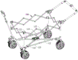
FIG. 1 is a schematic view of a cart according to an embodiment of the present disclosure in an unfolded state;
FIG. 2 is a front view of the cart of FIG. 1;
FIG. 3 is a schematic view of the frame of the cart of FIG. 1 in a collapsed configuration;
FIG. 4 is a schematic view of the upper handle bar of FIG. 3 in a folded state;
FIG. 5 is a front view of the cart of FIG. 4;
FIG. 6 is a schematic view of a cart according to another embodiment of the present disclosure in an unfolded state;
fig. 7 is a front view of the cart of fig. 6.
Reference numerals in the drawings are described as follows:
100. a frame; 111. an accommodating space; 112. a storage space;
120. a bottom bracket assembly; 121. a base; 122. a bottom stay; 123. two folding rods;
130. a connection assembly; 131. a column; 132. an upper connecting seat; 133. a lower connecting seat; 134. a slider;
140. a side stop assembly; 141. a first side stop assembly; 142. a second side stop assembly; 143. a scissors fork rod; 144. an upper connection part; 145. a lower connecting part;
150. a handle assembly; 151. a lower handle bar; 152. a handle bar is arranged on the upper part;
160. a wheel; 170. and a connecting seat.
Detailed Description
The following description of the technical solutions in the embodiments of the present application will be made clearly and completely with reference to the drawings in the embodiments of the present application, and it is apparent that the described embodiments are only some embodiments of the present application, not all embodiments. All other embodiments, which can be made by one of ordinary skill in the art without undue burden from the present disclosure, are within the scope of the present disclosure.
It will be understood that when an element is referred to as being "connected" to another element, it can be directly connected to the other element or intervening elements may also be present. When an element is referred to as being "disposed on" another element, it can be directly on the other element or intervening elements may also be present.
Unless defined otherwise, all technical and scientific terms used herein have the same meaning as commonly understood by one of ordinary skill in the art to which this application belongs. The terminology used herein in the description of the present application is for the purpose of describing particular embodiments only and is not intended to be limiting of the application. The term "and/or" as used herein includes any and all combinations of one or more of the associated listed items.
In this application, the terms "first," "second," and the like are used for descriptive purposes only and are not to be construed as indicating or implying relative importance or implicitly indicating the number, order of technical features indicated. Thus, a feature defining "a first" or "a second" may explicitly or implicitly include one or more such feature. In the description of the present application, the meaning of "plurality" is at least two, such as two, three, etc., unless explicitly defined otherwise.
Referring to fig. 1-5, the present application provides a cart including a frame 100 having a receiving space 111 and a handle assembly 150. The accommodating space 111 is provided therein with a liner for loading goods or seating a child. The frame 100 includes a base support assembly 120, a connection assembly 130, and a side rail assembly 140. The bottom support assembly 120 is horizontally arranged and is approximately rectangular, the four connecting assemblies 130 are arranged at the corner positions of the frame, and the side baffle assemblies 140 are arranged between two adjacent connecting assemblies 130 and form the accommodating space 111 by surrounding the bottom support assembly 120. The side stop assemblies 140 may be one set or two sets, and the structures of the two sets of side stop assemblies may be different or the same.
The handle assembly 150 includes a lower handle bar 151 and an upper handle bar 152 rotatably coupled to the frame 100, the lower handle bar 151 rotatably coupled to accommodate user pulls of different heights and arm lengths. In the folded state, the side rail assemblies are folded such that the opposite side rail assemblies are drawn toward each other and form the receiving space 112 at the top of the frame 100, and the upper handle bar 152 is rotatably disposed in the receiving space 112 with respect to the lower handle bar 151. The storage space 112 is formed by gaps between the side baffle assemblies 140 in the folded state, so that the handle assembly does not exceed the frame in the height direction, and the storage, packaging and transportation are convenient as a whole; and when the device is unfolded and used, the device meets the length and size requirements of users.
In addition, the folding/unfolding operation for the upper handle bars 152 is also convenient, and after the specific frame 100 is folded, the upper handle bars 152 are rotated and placed into the storage space 112 from above the frame; when the frame is unfolded, the upper handle 152 is rotated to withdraw from the storage space 112 from above, and then the frame 100 is unfolded.
In one embodiment, the side guard assembly 140 includes one or more pairs of serially connected scissors rods 143, with both ends of the scissors rods 143 being respectively hinged to the connection assembly 130 or to the other pair of scissors rods 143. The pair of scissor rods 143 comprises two or more rods, which in the illustration comprise only two rods hinged to each other.
At least one of the connection assembly 130 and the side rail assembly 140 is connected with the bottom bracket assembly 120 with respect to the structure of the frame.
Referring to fig. 1 and 3, in one embodiment, the connection assembly 130 includes a column 131 connected to the bottom bracket assembly 120, an upper connection seat 132 is provided at the top of the column 131, and a slider 134 is slidably installed on the column 131; each pair of scissor rods 143 has an upper link 144 and a lower link 145, the upper link 144 of a pair of scissor rods 143 adjacent to the upright 131 being hinged to the upper link 132, the lower link 145 being hinged to the slider 134, the slider 134 sliding downwardly during folding such that the height of the frame 100 remains consistent before and after folding.
Wherein, the frame 100 has a length direction X and a width direction Y as shown in fig. 1, the side rail assembly 140 includes a first side rail assembly 141 extending in the length direction and a second side rail assembly 142 extending in the width direction, and the handle assembly 150 is disposed at one side of the second side rail assembly 142. The number of corresponding scissors 143:
for example, the second side guard assembly includes a pair of scissors bars, and the hinge points of the handle assembly 150 and the two bars of the scissors bars overlap each other in a lengthwise projection, and in a folded state, the upper handle bar may be just between the two bars.
Referring to fig. 1, 3 and 4, for another example, the second side stop assembly 142 includes two pairs of scissor rods 143 and the first side stop assembly 141 includes three pairs of scissor rods 143. Each pair of the scissor levers 143 has an upper connecting portion 144 and a lower connecting portion 145, the upper connecting portions 144 of two adjacent pairs of the scissor levers 143 being hinged to each other, the lower connecting portions 145 being hinged to each other, and in the folded state, the upper handle bars 152 are located above the upper connecting portions 144.
In one embodiment, the lower handle bar 151 and the upper handle bar 152 are straight bars that facilitate passage through the gap of the scissor bars in the folded state.
Referring to fig. 5, in an embodiment, the upright 131 is vertically disposed, and the lower handle bar 151 is vertically disposed in a folded state, and the upper handle bar 152 is perpendicular to the lower handle bar 151, so that the cart approaches a rectangular structure in the folded state, and is convenient for packaging.
The connecting assembly 130 further includes a lower connecting seat 133 disposed at the bottom of the upright, the bottom bracket assembly 120 includes a base 121 disposed at the center (intersection of diagonal lines), and a bottom bracket 122 with two ends respectively hinged between the base 121 and the lower connecting seat 133, and when the folding assembly is folded, the base 121 moves upwards to drive the side stop assemblies 140 to be close to each other. In an embodiment, in the folded state, the upper handle 152 abuts against the base 121, so as to avoid the upper handle 152 from rotating to be transited to be engaged with the side block assembly 140, and thus the unfolding operation is affected. After the lining is sleeved, the thickness of the lining is small and can be ignored, so that the lining is not in conflict.
In order to improve the bearing capacity of the bottom bracket assembly 120, in one embodiment, two folding bars 123 are disposed between adjacent bottom bracket bars 122, and the folding bars 123 are tiled in the unfolded state, which means that the upper surfaces of the bottom bracket assembly 120 are substantially coplanar, and the structural strength of the bottom bracket assembly in the unfolded state is improved. Folded in half in the folded state. In a preferred embodiment, as shown in fig. 6 and 7, the two folding bars 123 are at least two and symmetrically arranged. In one embodiment, the bottom of the lower link seat 133 is provided with wheels 160. In one embodiment, the wheel 160 is detachably connected to the lower connecting seat 133. The detachable wheel 160 is individually packaged in consideration of the wheel size, especially when the size greatly affects the packaging, when the aforementioned cart is in a folded state, the shape does not include the wheel.
The lower handle bar 151 is rotatably connected with the bottom bracket assembly 120 through the connection base 170, and the lower handle bar 151 is slidably connected with the connection base 170. The height of the lower handle bar 151 can be adjusted so that the hinge point between the upper handle bar and the lower handle bar is reduced in the unfolded state to meet the use requirement and in the folded state.
In the handcart, the handle component does not exceed the frame in the height direction in the folded state, so that the handcart is integrally convenient to store, pack and transport; and when the device is unfolded and used, the device meets the length and size requirements of users. The folding and unfolding operation of the upper handle bar is also facilitated because the upper side of the storage space is opened.
The technical features of the above embodiments may be arbitrarily combined, and all possible combinations of the technical features in the above embodiments are not described for brevity of description, however, as long as there is no contradiction between the combinations of the technical features, they should be considered as the scope of the description. When technical features of different embodiments are embodied in the same drawing, the drawing can be regarded as a combination of the embodiments concerned also being disclosed at the same time.
The foregoing examples represent only a few embodiments of the present application, which are described in more detail and are not thereby to be construed as limiting the scope of the claims. It should be noted that it would be apparent to those skilled in the art that various modifications and improvements could be made without departing from the spirit of the present application, which would be within the scope of the present application.
Claims (10)
1. A cart having an expanded state and a collapsed state, the cart comprising:
the frame is provided with a containing space and comprises a bottom support assembly horizontally arranged, a connecting assembly arranged at the corner position of the frame, and a side baffle assembly arranged between two adjacent connecting assemblies and encircling the bottom support assembly to form the containing space;
the handle assembly comprises a lower handle rod and an upper handle rod which are connected in a rotating mode, the lower handle rod is connected with the frame in a rotating mode, the side baffle assemblies are folded and mutually close in a folding mode, a storage space is formed at the top of the frame, and the upper handle rod is placed in the storage space in a rotating mode.
2. The cart of claim 1, wherein the side dam assembly includes one or more pairs of serially connected scissor bars.
3. A cart according to claim 2, wherein,
the connecting assembly comprises a stand column connected with the bottom support assembly, an upper connecting seat is arranged at the top of the stand column, and a sliding piece is slidably arranged on the stand column;
each pair of scissors rods is provided with an upper connecting part and a lower connecting part, the upper connecting part of the pair of scissors rods adjacent to the upright is hinged with the upper connecting seat, and the lower connecting part is hinged with the sliding part.
4. The cart of claim 2, wherein the side rail assembly includes a first side rail assembly extending in a length direction and a second side rail assembly extending in a width direction, the handle assembly being disposed on one side of the second side rail assembly.
5. The cart of claim 4, wherein the first side stop assembly includes three pairs of scissor bars and the second side stop assembly includes two pairs of scissor bars.
6. The cart of claim 5, wherein each pair of said scissor arms has an upper attachment portion and a lower attachment portion, the upper attachment portions of two adjacent pairs of scissor arms being hinged to each other and the lower attachment portions being hinged to each other, said upper handle bar being above the upper attachment portions in the collapsed condition.
7. The cart of claim 1, wherein the frame has a height that is uniform between an expanded configuration and a collapsed configuration, the frame height being greater than or equal to a height of the handle assembly in the collapsed configuration.
8. The cart of claim 1, wherein the connecting assembly comprises a vertical column, a lower connecting seat is arranged at the bottom of the vertical column, the bottom support assembly comprises a base arranged at the center, and bottom support rods with two ends respectively hinged between the base and the lower connecting seat, and the base moves upwards to drive the side baffle assemblies to be close to each other when the cart is folded.
9. The cart of claim 8, wherein in the collapsed condition, the upper handle bar abuts the base.
10. The cart of claim 8, wherein a folding bar is disposed between adjacent bottom struts, the folding bar being tiled in an unfolded state and folded in half in a folded state.
Priority Applications (1)
| Application Number | Priority Date | Filing Date | Title |
|---|---|---|---|
| CN202222874340.XU CN218907292U (en) | 2022-10-27 | 2022-10-27 | Barrows with wheels |
Applications Claiming Priority (1)
| Application Number | Priority Date | Filing Date | Title |
|---|---|---|---|
| CN202222874340.XU CN218907292U (en) | 2022-10-27 | 2022-10-27 | Barrows with wheels |
Publications (1)
| Publication Number | Publication Date |
|---|---|
| CN218907292U true CN218907292U (en) | 2023-04-25 |
Family
ID=86010014
Family Applications (1)
| Application Number | Title | Priority Date | Filing Date |
|---|---|---|---|
| CN202222874340.XU Active CN218907292U (en) | 2022-10-27 | 2022-10-27 | Barrows with wheels |
Country Status (1)
| Country | Link |
|---|---|
| CN (1) | CN218907292U (en) |
Cited By (1)
| Publication number | Priority date | Publication date | Assignee | Title |
|---|---|---|---|---|
| CN118254853A (en) * | 2024-03-13 | 2024-06-28 | 浙江普莱德休闲用品有限公司 | Folding trolley |
-
2022
- 2022-10-27 CN CN202222874340.XU patent/CN218907292U/en active Active
Cited By (1)
| Publication number | Priority date | Publication date | Assignee | Title |
|---|---|---|---|---|
| CN118254853A (en) * | 2024-03-13 | 2024-06-28 | 浙江普莱德休闲用品有限公司 | Folding trolley |
Similar Documents
| Publication | Publication Date | Title |
|---|---|---|
| US20210300450A1 (en) | Foldable Wagon | |
| CN218907292U (en) | Barrows with wheels | |
| CN216374594U (en) | Folding bicycle | |
| CN106037347B (en) | Folding bed | |
| CN220682423U (en) | Frame and transport vechicle | |
| CN113460134A (en) | Folding bicycle frame | |
| CN215398871U (en) | Foldable trolley | |
| CN216185261U (en) | Foldable cart | |
| CN212766425U (en) | Baby carriage frame convenient to fold | |
| CN218750843U (en) | Bearing device | |
| CN218558884U (en) | Folding state height-keeping unchanged traveling vehicle | |
| CN221438032U (en) | Foldable carrying device | |
| CN220243339U (en) | Bearing device | |
| CN219406506U (en) | Folding cart | |
| CN217835672U (en) | Foldable push-pull vehicle | |
| CN108420224B (en) | Folding bed | |
| CN220349739U (en) | Handcart frame | |
| CN219857189U (en) | Expandable trolley | |
| CN221438033U (en) | Foldable trolley | |
| CN218287777U (en) | Folding handcart | |
| CN217100134U (en) | Carrying device | |
| CN215361431U (en) | Folding bicycle frame | |
| CN218661869U (en) | Manpower carrying device | |
| CN218141616U (en) | Bearing device | |
| CN219339485U (en) | Double-sliding sleeve gathering trailer |
Legal Events
| Date | Code | Title | Description |
|---|---|---|---|
| GR01 | Patent grant | ||
| GR01 | Patent grant |