CN218902580U - Mechanical vibration classifying screen - Google Patents
Mechanical vibration classifying screen Download PDFInfo
- Publication number
- CN218902580U CN218902580U CN202120365610.7U CN202120365610U CN218902580U CN 218902580 U CN218902580 U CN 218902580U CN 202120365610 U CN202120365610 U CN 202120365610U CN 218902580 U CN218902580 U CN 218902580U
- Authority
- CN
- China
- Prior art keywords
- screen
- frame
- shaft
- excitation
- vibration
- Prior art date
- Legal status (The legal status is an assumption and is not a legal conclusion. Google has not performed a legal analysis and makes no representation as to the accuracy of the status listed.)
- Active
Links
Images


Landscapes
- Combined Means For Separation Of Solids (AREA)
Abstract
The utility model discloses a mechanical vibration classifying screen, which comprises a base, an excitation table and a classifying screen bed, wherein the base is provided with a vibrating screen; an excitation table is movably arranged on the base in a split manner; a classifying screen bed is arranged on a vibrating seat of the vibration excitation table; the classifying screen bed comprises more than three screen frames which are vertically stacked; a hasp is arranged between the bottommost sieve bed frame and the side wall of the topmost sieve bed frame; a screen is movably arranged between the adjacent screen frames in a split mode; the bottom of the sieve bed frame at the bottom is fixedly provided with a sealing bottom plate which is fixedly connected with the vibration seat. The advantages are that: the screen cloth is convenient to replace, clean and maintain, and meanwhile, the material can bounce slightly while reciprocating on the screen cloth, so that the separation efficiency is improved.
Description
Technical field:
the utility model relates to sorting equipment, in particular to a mechanical vibration classifying screen.
The background technology is as follows:
the vibrating screen is a vibrating screening mechanical device suitable for any particles, powder and mucus, and is a common screening device in the food, medicine, chemical and metallurgical industries in China at present.
In the production and processing process of sunflower seeds, a linear vibrating screen or a swinging vibrating screen is often used for sorting the sunflower seeds with different particle sizes. The linear vibrating screen uses vibration motor excitation as vibration source to make material be thrown up on screen, at the same time makes forward linear motion, the material uniformly enters the feed inlet of screening machine from feeder, and several specifications of oversize material and undersize material are produced by means of multilayer screen, and are respectively discharged from respective outlets. The sieve mesh blocking device has the defects that in the use process, materials are thrown up on the sieve mesh to skip the sieve mesh to cause sieve leakage, and the materials are blocked in the sieve mesh of the sieve mesh in the throwing-up and falling process to cause the sieve mesh blocking; the whole screening efficiency is low, and the swinging type vibrating screen is a low-frequency rotary vibrating screen imitating manual shaking, the moving direction of the screen is perpendicular to the central line of the supporting rod or the suspension rod, and the materials on the screen surface move towards the discharge end at a certain speed under the action of inertia due to the swinging motion of the screen, so that the materials are screened simultaneously. The method has the defect that the materials cannot fall into the sieve holes due to the fact that the materials slide on the sieve mesh due to inertia, so that the separation efficiency is low.
Meanwhile, a plurality of screens used by the existing vibrating screen are fixed in a screen bed frame, and the screens and screen pressing strips are required to be taken out from the screen bed frame completely when the screens are replaced, cleaned and maintained, so that the vibrating screen is complex in operation and time and labor are wasted.
The utility model comprises the following steps:
in order to solve the problems, the utility model aims to provide the mechanical vibration classifying screen which is convenient for replacing, cleaning and maintaining the screen, and meanwhile, the material can bounce slightly while reciprocating on the screen, so that the separation efficiency is improved.
The utility model is implemented by the following technical scheme: the mechanical vibration classifying screen comprises a base, an excitation table and a classifying screen bed; the excitation table is movably arranged on the base in a split mode; the classifying screen bed is arranged on the vibrating seat of the vibration excitation table; the classifying screen bed comprises more than three screen frames which are vertically stacked; a hasp is arranged between the bottommost sieve bed frame and the side wall of the topmost sieve bed frame; the screen frame comprises a frame, a grid frame is fixedly arranged on the inner side of the frame, and the top surface of the grid frame is flush with the top surface of the frame; the bottom of each transverse frame of the grid frame is correspondingly provided with a screen pressing bar parallel to the transverse frame; the bottom surface of the screen pressing bar is flush with the bottom surface of the frame; support columns are uniformly distributed between the screen pressing strips and the transverse frames corresponding to the upper parts of the screen pressing strips; a screen is movably arranged between the adjacent screen frames in a split mode; an elastic ball separation net is fixedly arranged at the bottom of the grid frame below the screen net, and the elastic ball separation net, the frame and the grid frame form an elastic ball bin; a rubber elastic ball is arranged in the elastic ball bin; the bottom of the sieve bed frame is fixedly provided with a sealing bottom plate which is fixedly connected with the vibration seat.
Preferably, the side walls at the two sides of the front end and the rear end of the excitation base are provided with fixing bolts which are horizontally arranged; a fixing groove corresponding to the fixing bolt is vertically formed in the top of the side wall of the base; the fixing bolts are correspondingly arranged in the fixing grooves.
Preferably, the excitation platform comprises an excitation base; the vibration seat is arranged above the excitation base; a plate spring is arranged between the excitation base and two sides of the vibration base; an excitation motor is fixedly arranged on the excitation base; eccentric bearings are arranged at two ends of a motor shaft of the excitation motor, and a pull rod with the axial direction perpendicular to the axial direction of the motor shaft is arranged on the eccentric bearings; an excitation shaft parallel to the motor shaft is rotatably arranged on the vibration seat; the shaft head of the excitation shaft is rotatably arranged in a shaft hole of a shaft seat on the vibration seat; the top end of the pull rod is movably connected with the vibration beam.
Preferably, the rotating shaft seat comprises a fixed seat and a movable seat which are mutually attached and fixed, and corresponding semicircular grooves are respectively formed in the side walls of the fixed seat and the movable seat which are attached; the two semicircular grooves form a round rotating shaft hole.
Preferably, a through hole is formed in the solid excitation shaft, a shaft sleeve is sleeved in the through hole, and the pull rod is inserted and fixed in the shaft sleeve.
Preferably, round holes are formed in the opposite side walls of the hollow vibrating beam, reinforcing blocks are fixedly arranged in the hollow vibrating beam, and through holes corresponding to the round holes are formed in the reinforcing blocks; the pull rod penetrates through the round hole and is fixedly connected to the reinforcing block in an inserting mode.
Preferably, a screen replacement hoisting device is arranged above the classifying screen bed; the screen replacement hoisting device comprises a fixing frame fixed with the base; four corners of the fixing frame are provided with screw rod lifters; a lifting motor is arranged on the fixing frame; the lifting motor is in transmission connection with an input shaft of the screw rod lifter; a lifting rope is arranged at the bottom end of a screw rod of the screw rod elevator, and a hook is arranged on the lifting rope; lifting lugs corresponding to the hooks are correspondingly arranged on the outer walls of the left side and the right side of the frame below the bottom end of the screw rod.
Preferably, a screen replacement hoisting device is arranged above the classifying screen bed; the screen replacement hoisting device comprises a fixing frame fixed with the base; a lifting motor is arranged on the fixing frame; lifting chain wheel sets are respectively arranged on the fixing frames above the outer walls of the left side and the right side of the frame; each lifting chain wheel group comprises two driving chain wheels, two driven chain wheels, a closing chain and two lifting chains; the two driving chain wheels are fixed on the output shaft of the lifting motor; the closing chain is arranged on one driving chain wheel and one driven chain wheel in a meshed sleeve manner; the other driving chain wheel and the other driven chain wheel are respectively sleeved with a hoisting chain; a connecting pin shaft is arranged between the side wall at one end of the hoisting chain and the side wall of the closed chain which is arranged in parallel; the other end of the hoisting chain sags, and a hook is arranged at the top end of the hoisting chain; lifting lugs corresponding to the hooks are correspondingly arranged on the outer walls of the left side and the right side of the frame below the hanging end of the hoisting chain.
Preferably, a limit switch is arranged between the side wall of the hoisting chain and the side wall of the closed chain which is arranged in parallel, a contact of the limit switch is in movable contact with the connecting pin shaft, and the limit switch is controlled in linkage with the lifting motor.
Preferably, a feed hopper is arranged above the classifying screen bed; a closed air collecting box is arranged on the outer side wall of the base; a dust collection port and an air outlet are arranged on the air collection box; the air outlet is communicated with the air inlet of the dust removing device; a dust removing opening is formed in the sealing bottom plate below the feeding hopper; the dust removing port is communicated with the dust collecting port in a sealing way through a ventilation hose.
Preferably, a hopper dust collection port communicated with the dust collection port is arranged on the vertical side wall of the feed hopper; the dust removing port of the hopper is provided with an air regulating device.
Preferably, the air regulating device is a shutter.
Preferably, the air regulating device comprises a fixed orifice plate and a movable orifice plate; the hopper dust removal port is fixedly provided with a fixed orifice plate, a movable orifice plate is attached to the fixed orifice plate, an adjusting bolt is arranged on the fixed orifice plate, a strip-shaped adjusting screw hole is formed in the movable orifice plate, and the adjusting bolt is arranged in the adjusting screw hole.
Preferably, an inverted V-shaped distributor is arranged on the inner wall of the feed hopper above the dust removal opening of the hopper.
The utility model has the advantages that: compared with the prior art, the material can bounce slightly while reciprocating on the screen, so that the screening efficiency is improved; the base and the excitation table are fixed in a split manner so as to be convenient for transportation, equipment is prevented from vibrating and damaging in the transportation process, the screen surface angle of the classifying screen can be adjusted according to the screening working condition, the screen frame is clamped and fixed up and down through the snap fastener, and the screen is clamped and fixed in a split manner by the upper screen frame and the lower screen frame so as to be convenient for cleaning, replacement and maintenance of the screen; the number of layers of the screen frame can be easily adjusted according to working conditions, and screens with different meshes can be easily replaced; the classifying screen bed swings at a high frequency and a small amplitude by taking the excitation shaft as an axis, so that the material can bounce a small amplitude while reciprocating on the screen, the material is prevented from blocking the screen holes of the screen, and the screening efficiency is improved; the vibration excitation shaft is rotatably arranged on the vibration seat, when the vibration seat is driven along with the pull rod to vibrate, the stress at the joint of the vibration excitation shaft and the vibration seat is reduced, the service life of the vibration excitation shaft is prolonged, the long-term stable operation of equipment is ensured, the phenomenon that the traditional vibration excitation shaft is fixedly connected with the vibration seat, the stress is generated between the connecting point of the pull rod and the vibration excitation shaft, the mechanical fatigue of the pull rod is caused, the pull rod is broken, the vibration frequency cannot be improved, noise is generated, the operation is unstable, and the production efficiency is influenced is avoided; the lifting device for replacing the screen has the advantages of simple integral structure, convenience in use and easiness in maintenance, drives the screen frame to ascend and descend, realizes hanging of the screen frame, shortens maintenance time for replacing or cleaning and maintaining the screen, and improves production efficiency.
Description of the drawings:
fig. 1 is an overall schematic diagram of example 1.
Fig. 2 is an assembly schematic of example 1.
Fig. 3 is an overall schematic view of the excitation stand.
Fig. 4 is an overall schematic diagram of the rotating shaft seat.
Fig. 5 is an assembly schematic diagram of the rotating shaft seat.
Fig. 6 is an overall schematic view of a solid excitation shaft.
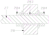
Fig. 7 is a cross-sectional view of a solid excitation shaft structure.
Fig. 8 is an overall schematic view of a hollow excitation shaft.
Fig. 9 is a schematic view of hollow excitation shaft assembly.
Fig. 10 is a cross-sectional view of a hollow excitation shaft structure.
Fig. 11 is an overall schematic of a classifying screen bed.
Fig. 12 is an assembled schematic view of a classifying screen bed.
Fig. 13 is an overall schematic view of the top sifting bed frame.
Fig. 14 is an overall schematic view of a sieve frame provided with a resilient ball spacer.
Fig. 15 is an overall schematic diagram of example 2.
Fig. 16 is a schematic use diagram of example 2.
Fig. 17 is an overall schematic diagram of example 3.
Fig. 18 is an overall schematic of a lifting sprocket set.
Fig. 19 is an enlarged partial schematic view of a portion a of fig. 18.
Fig. 20 is an enlarged partial schematic view of portion B of fig. 18.
FIG. 21 is a schematic representation of the use of example 3.
Fig. 22 is an overall schematic of a lifting sprocket set with limit switches.
Fig. 23 is a schematic diagram of a screen replacement lifting device with limit switch.
Fig. 24 is an overall schematic of example 4.
Fig. 25 is a bottom view of fig. 22.
FIG. 26 is a schematic illustration of the connection of a bellows.
Fig. 27 is a schematic view of two dust removal ports.
FIG. 28 is an overall schematic view of a hopper in which the air register is a shutter.
FIG. 29 is a schematic view showing the connection of the wind collecting box of example 5.
Figure 30 is a schematic view of the whole hopper with the distributor.
FIG. 31 is a schematic view of a hopper in which the air register is a fixed orifice plate and a movable orifice plate.
The specific embodiment is as follows:
example 1: as shown in fig. 1 and 2, the mechanical vibration classifying screen comprises a base 1, an excitation table 2 and a classifying screen bed 3, wherein as shown in fig. 3, the excitation table 2 comprises an excitation base 21; a vibration seat 22 is arranged above the excitation base 21; a plate spring 23 which is obliquely arranged between the two sides of the excitation base 21 and the vibration base 22; an excitation motor 24 and a driven shaft 25 axially parallel to the motor shaft of the excitation motor 24 are fixedly arranged on the excitation base 22; the exciting motor 24 is in transmission connection with a driven shaft 25; eccentric bearings 26 are arranged at two ends of the driven shaft 25, and a pull rod 27 with the axial direction perpendicular to the axial direction of the motor shaft is arranged on the eccentric bearings 26; an excitation shaft 28 parallel to the motor shaft 25 is rotatably arranged on the vibration seat 22; specifically, the shaft head 281 of the excitation shaft 28 is rotatably disposed in the shaft hole 222 of the shaft seat 221 on the vibration seat 22; as shown in fig. 4 and 5, the rotating shaft seat 221 includes a fixed seat 223 and a movable seat 224 which are mutually attached, and corresponding semicircular grooves 225 are respectively formed on the side walls of the fixed seat 223 and the movable seat 224 which are mutually attached; two semicircular grooves 225 form a circular rotating shaft hole 222; the rotating shaft seat 221 is formed by mutually attaching, assembling and combining a fixed seat 223 and a movable seat 224, so that the fixed exciting shaft 28 is convenient to install; the top end of the pull rod 27 is movably connected with the excitation shaft 28. Specifically, as shown in fig. 6 and 7, a through hole 282 is formed in the solid excitation shaft 28, a shaft sleeve 283 is sleeved in the through hole 2812, and the pull rod 27 is inserted and fixed in the shaft sleeve 283; the pull rods 27 on two sides of the shaft sleeve 283 are respectively and rotatably connected with a fixing nut 284 in a screw manner, and the pull rods 27 are fixed on the shaft sleeve 283 through the fixing nuts 284; or as shown in fig. 8 to 10, a circular hole 285 is formed in the side wall opposite to the hollow exciting shaft 28, a reinforcing block 286 is fixedly arranged in the hollow exciting shaft 28, and a through hole 287 corresponding to the circular hole 285 is arranged on the reinforcing block 286; the pull rod 27 passes through the round hole 285 and is fixedly inserted on the reinforcing block 286; the pull rods 27 on two sides of the excitation shaft 28 are respectively and rotatably connected with a fixing nut 284 in a screw manner, the pull rods 27 are fixed on the excitation shaft 28 through the fixing nuts 284, and the outer wall of the reinforcing block is integrally and fixedly provided with a shaft head 281; the pull rod 27 is fixed on the excitation shaft 28 through a sleeve or a reinforcing block 285, so that stress generated when the pull rod 27 drives the excitation shaft 28 to reciprocate is reduced, the vibration frequency of the pull rod 27 for driving the vibration seat 22 is improved, and noise is reduced; meanwhile, the service lives of the pull rod 27 and the excitation shaft 28 are prolonged, the maintenance times are reduced, and the long-term stable operation of the equipment is ensured; as shown in fig. 11 to 14, the classifying screen bed 3 includes three screen frames 31 stacked one above the other; a hasp 311 is arranged between the bottommost sieve bed frame 31 and the side wall of the topmost sieve bed frame 31; the screen frame 31 comprises a frame 32, a grid frame 33 is fixedly arranged on the inner side of the frame 32, and the top surface of the grid frame 33 is flush with the top surface of the frame 32; the bottom of each transverse frame 34 of the grid frame 33 is correspondingly provided with a screen pressing bar 35 parallel to the transverse frames 34; the bottom surface of the screen pressing bar 35 is flush with the bottom surface of the frame 32; support columns 36 made of hard rubber are uniformly distributed between the screen pressing strips 35 and the corresponding transverse frames 34 above; a screen 37 is movably arranged between the adjacent screen frames 31 in a split manner; a spring ball separation net 38 is fixedly arranged at the bottom of the grid frame 33 below the screen 37, and the spring ball separation net 38, the frame 32 and the grid frame 33 form a spring ball bin 39; a rubber elastic ball is arranged in the elastic ball bin 39; a sealing bottom plate 4 is fixedly arranged at the bottom of the sieve bed frame 31 at the bottom; the screen frame 31 is clamped and fixed up and down through the buckles 311, and the screen 37 is clamped and fixed by the upper screen frame 31 and the lower screen frame 31 in a split manner, so that the screen is convenient to clean, replace and maintain; the number of layers of the screen frame 31 can be easily adjusted according to working conditions, and screens 37 with different meshes can be easily replaced; the side walls on the two sides of the front end and the rear end of the excitation base 21 are provided with fixing bolts 29 which are horizontally arranged; a fixing groove 11 corresponding to the fixing bolt 29 is vertically formed on the top of the side wall of the base 1; the fixing bolts 29 are correspondingly arranged in the fixing grooves 11; the fixing bolts 29 are screwed on the fixing bolts 29, so that the fixing bolts 29 are fixed in the fixing grooves 11, the base 1 and the excitation table 2 are fixed in a split mode, transportation is facilitated, vibration damage of equipment in the transportation process is prevented, meanwhile, the screening surface angle of the classifying screen can be adjusted according to screening working conditions, and screening efficiency is improved; the sealing bottom plate 4 is fixedly connected with the vibration seat 22.
Working principle: the exciting motor 24 drives the driven shaft 25 to rotate, the rotating driven shaft 25 drives the pull rod 27 on the eccentric bearings 26 at the two ends to reciprocate, and the pull rod 27 drives the exciting shaft 28 to drive the vibration seat 22 to vibrate; the classifying screen bed 3 swings at a high frequency and a small amplitude by taking the exciting shaft 28 as an axis, so that the material can bounce a small amplitude while reciprocating on the screen 37, the material is prevented from blocking the screen holes of the screen 37, and the screening efficiency is improved. The exciting shaft 28 arranged on the vibration seat 22 is rotated, when the vibration seat 22 is driven to vibrate along with the pull rod 27, the stress at the joint of the exciting shaft 28 and the vibration seat 22 is reduced, the service life of the exciting shaft 28 is prolonged, the long-term stable operation of equipment is ensured, the traditional fixed connection of the exciting shaft and the vibration seat is avoided, the stress is generated between the connecting point of the pull rod and the exciting shaft, the mechanical fatigue of the pull rod is caused, the pull rod is broken, the vibration frequency cannot be improved, noise is generated, the operation is unstable, and the production efficiency is influenced.
Example 2: the mechanical vibration classifying screen with the same integral structure as that of the embodiment 1 is different in that, as shown in fig. 15, a screen replacement lifting device 6 is arranged above a classifying screen bed 3; the screen replacement hoisting device 6 comprises a fixed frame 61 fixed with the base 1; screw lifters 62 are provided at four corners of the fixing frame 61; a lifting motor 63 is arranged on the fixed frame 61; the lifting motor 63 is in transmission connection with an input shaft of the screw lifter 62; a lifting rope 65 is arranged at the bottom end of a screw rod 64 of the screw rod lifter 62, and a hook 66 is arranged on the lifting rope 65; lifting lugs 67 corresponding to the hooks 66 are correspondingly arranged on the outer walls of the left side and the right side of the frame 32 below the bottom end of the screw rod 64.
When the screen replacement hoisting device 6 is used, the hasp 311 is opened; firstly, a screw elevator 62 is driven by an elevating motor 63 to control a screw 64 to descend, and a hook 66 is hung on corresponding lifting lugs 67 on two sides of a screen frame 31 above a screen 37 to be replaced or cleaned and maintained; as shown in fig. 16, the lifting motor 63 drives the screw lifter 62 to control the screw 64 to lift, so as to lift the screen frame 31 above the screen 37 to be replaced or cleaned; exposing, removing, replacing or cleaning and maintaining the screen 37 clamped and fixed between the upper screen frame 31 and the lower screen frame 31; the screen replacement lifting device 6 is simple in integral structure, convenient to use and easy to maintain, and the screw lifter 62 drives the screen frame 31 to lift up and down so as to realize lifting of the screen frame 31, so that the maintenance time for replacing or cleaning and maintaining the screen 37 is shortened, and the production efficiency is improved.
Example 3:
a mechanical vibration classifying screen having the same overall structure as that of the embodiment 1, except that, as shown in fig. 17 to 20, a screen replacement lifting device 6 is provided above the classifying screen bed 3; the screen replacement hoisting device 6 comprises a fixed frame 61 fixed with the base 1; a lifting motor 63 is arranged on the fixed frame 61; lifting chain wheel sets 68 are respectively arranged on the fixing frames 61 above the outer walls of the left side and the right side of the frame 32; each hoist chain wheel set 68 includes two drive sprockets 681, two driven sprockets 682, a closure chain 683, and two hoist chains 684; two driving sprockets 681 are fixed to the output shaft of the lift motor 63; a closure chain 683 is engaged over a drive sprocket 681 and a driven sprocket 682; a hoisting chain 684 is respectively sleeved and meshed on the other driving chain wheel 681 and the other driven chain wheel 682; a connecting pin shaft 685 is arranged between the side wall of one end of the lifting chain 684 and the side wall of the parallel closed chain 683; the other end of the hoisting chain 684 sags and is provided with a hook 66 at the top end; lifting lugs 67 corresponding to the hooks 66 are correspondingly arranged on the outer walls of the left side and the right side of the frame 32 below the hanging end of the hanging chain 684.
Working principle: the lifting motor 63 drives the driving sprocket 681 to rotate, and the closed chain 683 on the driving sprocket 681 drives the driven sprocket 682 to synchronously rotate; when the driving sprocket 681 and the driven sprocket 682 synchronously rotate, the two hoist chains 684 on the driving sprocket 681 and the driven sprocket 682 synchronously rise or fall under the drive of the closing chain 683.
When the screen replacement hoisting device 6 is used, the hasp 311 is opened; the driving chain wheel 681 is driven to rotate by the lifting motor 63, and the lifting chains 684 on the driving chain wheel 681 and the driven chain wheel 682 are driven by the closing chain 683 to synchronously descend; hanging hooks 66 on a hanging chain 684 on corresponding lifting lugs 67 on two sides of the screen frame 31 above the screen 37 to be replaced or cleaned and maintained; as shown in fig. 21, the driving sprocket 681 is driven to rotate by the lifting motor 63, and the lifting chains 684 on the driving sprocket 681 and the driven sprocket 682 are driven by the closing chain 683 to synchronously lift the screen frame 31 above the screen 37 to be replaced or cleaned and maintained; the screen 37 clamped and fixed between the upper and lower screen frames 31 is exposed and removed for replacement or cleaning maintenance.
Further, as shown in fig. 22 and 23, a limit switch 69 is arranged between the side wall of the hoisting chain 684 and the side wall of the parallel closed chain 683, the contact of the limit switch 69 is movably contacted with the connecting pin shaft 685, and the limit switch 69 is controlled in linkage with the lifting motor 63; when the lifting chain 684 ascends to a certain position, the connecting pin shaft 685 between the lifting chain 684 and the closing chain 683 can touch the limit switch 69, the limit switch 69 acts to close the power supply of the lifting motor 63, and the overrun of the lifting chain 684 is effectively avoided by arranging the limit switch 69.
The screen replacing and lifting device 6 is simple in integral structure, convenient to use and easy to maintain, and the lifting chain 684 drives the screen frame 31 to lift up and down so as to realize lifting of the screen frame 31, so that the maintenance time for replacing or cleaning and maintaining the screen 37 is shortened, and the production efficiency is improved.
Example 4: a mechanical vibration classifying screen of the same overall structure as that of example 3 except that, as shown in fig. 24 to 26, a feed hopper 7 is provided above the classifying screen bed 3; the outer side wall of the base 1 is provided with a closed air collecting box 5; a dust collection port 51 and two air outlets 52 are arranged on the air collection box 5; the air outlet 52 is communicated with an air inlet of a dust removing device, and the dust removing device is a cyclone separator 8; a dust removing opening 41 is arranged on the sealing bottom plate 5 below the feed hopper 7; the dust removing port 41 is communicated with the dust collecting port 51 in a sealing way through a ventilation hose 53; or as shown in fig. 27, two dust collection ports 51 are arranged on the air collection box 5, and two dust collection ports 41 are arranged on the sealing bottom plate 5 below the feed hopper 7; each dust collection port 41 is communicated with the corresponding dust collection port 51 in a sealing way through a ventilation hose 53; dust generated by a blanking point below the feeding hopper 7 is sucked out, the dust quantity is reduced, and the problems that the original classifying screen adopts upper induced draft to remove dust, but air inlet of the upper induced draft only can enter from the upper part of the topmost screen, dust generated in the screen bed cannot be sucked out under negative pressure, and the dust removing effect cannot be achieved are solved.
Example 5: a mechanical vibration classifying screen having the same overall structure as that of example 4 except that, as shown in fig. 28 and 29, a hopper dust collection port 71 communicating with the dust collection port 51 is provided on the vertical side wall of the hopper 7; the hopper dust removal opening 71 is provided with an air adjusting device 72, and the air adjusting device 72 is a shutter 73; the air regulating device is a shutter, and the dust removal air quantity is regulated by regulating the angle of the shutter window.
Further, as shown in fig. 30, an inverted V-shaped distributor 78 is arranged on the inner wall of the feed hopper 7 above the hopper dust removal opening 71, and the distributor 78 uniformly distributes the material on the mesh surface of the screen 37, so as to avoid the material blocking the hopper dust removal opening 71.
Or as shown in fig. 31, the air regulating device 72 includes a fixed orifice 74 and a movable orifice 75; fixed orifice plate 74 is fixed to be equipped with at hopper dust removal mouth 71, fixed orifice plate 74 and the lateral wall structure as an organic whole of feeder hopper 7, the laminating is equipped with movable orifice plate 75 on fixed orifice plate 74, be equipped with adjusting bolt 76 on fixed orifice plate 74, set up rectangular shape and adjust screw 77 on movable orifice plate 75, adjusting bolt 76 arranges in adjusting screw 77 in, movable orifice plate 75 can carry out the displacement at fixed orifice plate 74 through adjusting screw 77, adjusts the size in space between fixed orifice plate 74 and the movable orifice plate 75 to realize adjustment dust removal amount of wind size.
Claims (14)
1. The mechanical vibration classifying screen is characterized by comprising a base, an excitation table and a classifying screen bed; the excitation table is movably arranged on the base in a split mode; the classifying screen bed is arranged on the vibrating seat of the vibration excitation table; the classifying screen bed comprises more than three screen frames which are vertically stacked; a hasp is arranged between the bottommost sieve bed frame and the side wall of the topmost sieve bed frame; the screen frame comprises a frame, a grid frame is fixedly arranged on the inner side of the frame, and the top surface of the grid frame is flush with the top surface of the frame; the bottom of each transverse frame of the grid frame is correspondingly provided with a screen pressing bar parallel to the transverse frame; the bottom surface of the screen pressing bar is flush with the bottom surface of the frame; support columns are uniformly distributed between the screen pressing strips and the transverse frames corresponding to the upper parts of the screen pressing strips; a screen is movably arranged between the adjacent screen frames in a split mode; an elastic ball separation net is fixedly arranged at the bottom of the grid frame below the screen net, and the elastic ball separation net, the frame and the grid frame form an elastic ball bin; a rubber elastic ball is arranged in the elastic ball bin; the bottom of the sieve bed frame is fixedly provided with a sealing bottom plate which is fixedly connected with the vibration seat.
2. The mechanical vibratory classifying screen according to claim 1, wherein the excitation stand includes an excitation base; the vibration seat is arranged above the excitation base; a plate spring is arranged between the excitation base and two sides of the vibration base; an excitation motor is fixedly arranged on the excitation base; eccentric bearings are arranged at two ends of a motor shaft of the excitation motor, and a pull rod with the axial direction perpendicular to the axial direction of the motor shaft is arranged on the eccentric bearings; an excitation shaft parallel to the motor shaft is rotatably arranged on the vibration seat; the shaft head of the excitation shaft is rotatably arranged in a shaft hole of a shaft seat on the vibration seat; the top end of the pull rod is movably connected with the vibration beam.
3. The mechanical vibration classifying screen according to claim 2, wherein fixing bolts are horizontally arranged on side walls on both sides of the front and rear ends of the excitation base; a fixing groove corresponding to the fixing bolt is vertically formed in the top of the side wall of the base; the fixing bolts are correspondingly arranged in the fixing grooves.
4. The mechanical vibration classifying screen according to claim 3, wherein the rotating shaft seat comprises a fixed seat and a movable seat which are mutually attached and fixed, and corresponding semicircular grooves are respectively formed on the side walls of the fixed seat and the movable seat which are attached; the two semicircular grooves form a round rotating shaft hole.
5. The mechanical vibration classifying screen according to claim 4, wherein a through hole is formed in the solid exciting shaft, a shaft sleeve is sleeved in the through hole, and the pull rod is inserted and fixed in the shaft sleeve.
6. The mechanical vibration classifying screen according to claim 4, wherein round holes are formed in opposite side walls of the hollow vibration beam, reinforcing blocks are fixedly arranged in the hollow vibration beam, and through holes corresponding to the round holes are formed in the reinforcing blocks; the pull rod penetrates through the round hole and is fixedly inserted into the reinforcing block, and the shaft head is integrally and fixedly arranged on the outer wall of the reinforcing block.
7. The mechanical vibratory screen of any of claims 1-6, wherein a screen replacement lifting device is positioned above the screen bed of the screen; the screen replacement hoisting device comprises a fixing frame fixed with the base; four corners of the fixing frame are provided with screw rod lifters; a lifting motor is arranged on the fixing frame; the lifting motor is in transmission connection with an input shaft of the screw rod lifter; a lifting rope is arranged at the bottom end of a screw rod of the screw rod elevator, and a hook is arranged on the lifting rope; lifting lugs corresponding to the hooks are correspondingly arranged on the outer walls of the left side and the right side of the frame below the bottom end of the screw rod.
8. The mechanical vibratory screen of any of claims 1-6, wherein a screen replacement lifting device is positioned above the screen bed of the screen; the screen replacement hoisting device comprises a fixing frame fixed with the base; a lifting motor is arranged on the fixing frame; lifting chain wheel sets are respectively arranged on the fixing frames above the outer walls of the left side and the right side of the frame; each lifting chain wheel group comprises two driving chain wheels, two driven chain wheels, a closing chain and two lifting chains; the two driving chain wheels are fixed on the output shaft of the lifting motor; the closing chain is arranged on one driving chain wheel and one driven chain wheel in a meshed sleeve manner; the other driving chain wheel and the other driven chain wheel are respectively sleeved with a hoisting chain; a connecting pin shaft is arranged between the side wall at one end of the hoisting chain and the side wall of the closed chain which is arranged in parallel; the other end of the hoisting chain sags, and a hook is arranged at the top end of the hoisting chain; lifting lugs corresponding to the hooks are correspondingly arranged on the outer walls of the left side and the right side of the frame below the hanging end of the hoisting chain.
9. The mechanical vibration classifying screen according to claim 8, wherein a limit switch is arranged between the side wall of the hoisting chain and the side wall of the closed chain arranged in parallel, a contact of the limit switch is movably contacted with the connecting pin shaft, and the limit switch is controlled in linkage with the lifting motor.
10. The mechanical vibratory classifying screen according to claim 1, wherein a feed hopper is provided above the classifying screen bed; a closed air collecting box is arranged on the outer side wall of the base; a dust collection port and an air outlet are arranged on the air collection box; the air outlet is communicated with the air inlet of the dust removing device; a dust removing opening is formed in the sealing bottom plate below the feeding hopper; the dust removing port is communicated with the dust collecting port in a sealing way through a ventilation hose.
11. The mechanical vibratory classifying screen according to claim 10, wherein a hopper dust collection port communicating with said dust collection port is provided on a vertical sidewall of said hopper; the dust removing port of the hopper is provided with an air regulating device.
12. The mechanical vibratory sizing screen of claim 11, wherein the air adjustment device is a louver.
13. The mechanical vibratory sizing screen of claim 11, wherein the air conditioning device comprises a fixed orifice plate and a movable orifice plate; the hopper dust removal port is fixedly provided with a fixed orifice plate, a movable orifice plate is attached to the fixed orifice plate, an adjusting bolt is arranged on the fixed orifice plate, a strip-shaped adjusting screw hole is formed in the movable orifice plate, and the adjusting bolt is arranged in the adjusting screw hole.
14. A mechanical vibratory classifying screen according to any of claims 11 to 13, wherein an inverted V-shaped distributor is provided on the inner wall of the hopper above the hopper dust removal opening.
Priority Applications (1)
| Application Number | Priority Date | Filing Date | Title |
|---|---|---|---|
| CN202120365610.7U CN218902580U (en) | 2021-02-09 | 2021-02-09 | Mechanical vibration classifying screen |
Applications Claiming Priority (1)
| Application Number | Priority Date | Filing Date | Title |
|---|---|---|---|
| CN202120365610.7U CN218902580U (en) | 2021-02-09 | 2021-02-09 | Mechanical vibration classifying screen |
Publications (1)
| Publication Number | Publication Date |
|---|---|
| CN218902580U true CN218902580U (en) | 2023-04-25 |
Family
ID=86037876
Family Applications (1)
| Application Number | Title | Priority Date | Filing Date |
|---|---|---|---|
| CN202120365610.7U Active CN218902580U (en) | 2021-02-09 | 2021-02-09 | Mechanical vibration classifying screen |
Country Status (1)
| Country | Link |
|---|---|
| CN (1) | CN218902580U (en) |
-
2021
- 2021-02-09 CN CN202120365610.7U patent/CN218902580U/en active Active
Similar Documents
| Publication | Publication Date | Title |
|---|---|---|
| CN102342581B (en) | Closed five-face screen roller tobacco stalk separator | |
| CN110420855B (en) | Material screening and grading device | |
| CN108246607B (en) | Double-layer multi-degree-of-freedom vibration screening device | |
| CN213001169U (en) | Oscillating screening machine for screening materials | |
| CN109731773A (en) | A kind of chemical industry powder classification vibration screening machine | |
| CN218902580U (en) | Mechanical vibration classifying screen | |
| CN110773418A (en) | Relaxation sieve | |
| CN209438973U (en) | A kind of biological particles wheat stalk separator | |
| CN114904757A (en) | Mechanical vibration classifying screen | |
| CN211726481U (en) | Gardenia flower charging sieve | |
| CN207371871U (en) | A kind of sorting unit of the white stick of resistor ceramic | |
| CN206935755U (en) | A kind of feedstuff vibration grading sieve for feed granules classification | |
| CN208613047U (en) | A kind of novel biomass particle sorting apparatus | |
| CN220092147U (en) | Efficient and stable wheat vibration screening machine | |
| CN220514429U (en) | Solid waste treatment screening plant | |
| CN220215727U (en) | Screening plant is used in abrasive material grinding apparatus processing | |
| CN216500677U (en) | High-efficient granule and powder sieve device | |
| CN220295149U (en) | Limestone particle screening device | |
| CN215613010U (en) | Vibration separation device of cable recovery equipment | |
| CN221537278U (en) | Linear feed sieving equipment | |
| CN220048948U (en) | Material screening device | |
| CN219859539U (en) | Dustless feeding device | |
| CN116371739B (en) | Multi-layer sorting device for solid waste treatment | |
| CN220781135U (en) | Graded screening device for edible fungi | |
| CN220177526U (en) | Rice sieve separator convenient to change screen cloth |
Legal Events
| Date | Code | Title | Description |
|---|---|---|---|
| GR01 | Patent grant | ||
| GR01 | Patent grant |