CN218901977U - Roller crusher for cement clinker crushing - Google Patents
Roller crusher for cement clinker crushing Download PDFInfo
- Publication number
- CN218901977U CN218901977U CN202222977011.8U CN202222977011U CN218901977U CN 218901977 U CN218901977 U CN 218901977U CN 202222977011 U CN202222977011 U CN 202222977011U CN 218901977 U CN218901977 U CN 218901977U
- Authority
- CN
- China
- Prior art keywords
- crushing
- roller
- driving
- gear
- driven
- Prior art date
- Legal status (The legal status is an assumption and is not a legal conclusion. Google has not performed a legal analysis and makes no representation as to the accuracy of the status listed.)
- Active
Links
Images


Classifications
-
- Y—GENERAL TAGGING OF NEW TECHNOLOGICAL DEVELOPMENTS; GENERAL TAGGING OF CROSS-SECTIONAL TECHNOLOGIES SPANNING OVER SEVERAL SECTIONS OF THE IPC; TECHNICAL SUBJECTS COVERED BY FORMER USPC CROSS-REFERENCE ART COLLECTIONS [XRACs] AND DIGESTS
- Y02—TECHNOLOGIES OR APPLICATIONS FOR MITIGATION OR ADAPTATION AGAINST CLIMATE CHANGE
- Y02P—CLIMATE CHANGE MITIGATION TECHNOLOGIES IN THE PRODUCTION OR PROCESSING OF GOODS
- Y02P40/00—Technologies relating to the processing of minerals
- Y02P40/10—Production of cement, e.g. improving or optimising the production methods; Cement grinding
Abstract
The utility model discloses a roller crusher for cement clinker crushing, which belongs to the technical field of cement clinker production and aims at the problems that when the roller crusher for cement clinker crushing in the prior art is used, cement clinker tends to lift a large amount of dust during crushing so as to pollute the surrounding environment; according to the utility model, the brush-removing mechanism is driven by the driving motor a to uniformly and rapidly brush out the cooked cement blocks, so that the problem of raising the follow-up crushing dust is reduced, the cooked cement blocks which are brushed out from the brush-removing mechanism fall onto the crushing mechanism under the action of dead weight, and the crushing mechanism in the shell is driven by the driving motor b to rapidly crush the cooked cement blocks.
Description
Technical Field
The utility model belongs to the technical field of cement clinker production, and particularly relates to a roller crusher for cement clinker crushing.
Background
The roller crusher is suitable for crushing medium hardness materials such as limestone, slag, coke, coal and other materials in the industries of cement, chemical industry, electric power, metallurgy, building materials, refractory materials and the like. The series of double-roller crushers mainly comprise rollers, roller supporting bearings, compaction and adjustment devices, driving devices and the like, and the toothed roller crushers mainly adopt special wear-resistant toothed rollers to rotate at high speed to split and crush materials (the traditional toothed roller crushers adopt low-speed extrusion and crushing), so that a mechanism with high productivity is formed. Crushing and grinding devices have important applications in chemical plants.
Chinese patent publication No.: CN212040667U discloses a roller crusher for cement clinker crushing, including the main tank, the bottom both sides fixedly connected with base of main tank, the top fixedly connected with crushing case of main tank rotates on the inner wall of crushing case to be connected with first bull stick, the first rotating teeth of fixedly connected with of surface of first bull stick, the one end surface transmission of first bull stick is connected with the drive belt, rotate on the bottom inner wall of crushing case to be connected with the second bull stick, the fixedly connected with second rotating teeth of second bull stick, fixedly connected with cooperation tooth on the both sides inner wall of crushing case, fixedly connected with collecting box on the top outer wall of crushing case. According to the cement secondary crushing device, the transmission belt is arranged, the second rotating teeth are driven to rotate through the rotation of the second rotating rod, and the multiple groups of second rotating teeth are matched with each other to rotate so as to carry out secondary cement crushing, so that the effect that only one power source is used for the secondary cement crushing is achieved, kinetic energy is saved, and the secondary cement crushing effect is achieved;
although the above patent basically solves the technical problems set forth in the background art, there is still a need for improvement in that cement clinker tends to raise a large amount of dust when it is crushed, thereby polluting the surrounding environment.
Therefore, there is a need for a roller crusher for pulverizing cement clinker, which solves the problem that when the roller crusher for pulverizing cement clinker in the prior art is used, a large amount of dust is often raised when the cement clinker is crushed, so that the surrounding environment is polluted.
Disclosure of Invention
The utility model aims to provide a roller crusher for crushing cement clinker, which aims to solve the problems in the background technology.
In order to achieve the above purpose, the present utility model provides the following technical solutions: the utility model provides a cement clinker is smashed and is used roller crusher, includes the shell, the top of shell is provided with the feeder hopper, the inside brushing mechanism that is located under the feeder hopper and is linked together with the feeder hopper that is provided with of shell, be provided with in the shell and be located brushing mechanism under and with brushing mechanism be linked together smashing mechanism, the lateral wall of shell is fixed with the driving motor a that the output is connected with one outside end of brushing mechanism, the lateral wall of shell is fixed with driving motor b that the output is connected with one outside end of smashing mechanism.
In the scheme, the brushing mechanism comprises a driving brush roller and a driven brush roller which are rotationally connected with the inner side wall of the shell, the driving brush roller and the driven brush roller are positioned under the feeding hopper, the output end of the driving motor a is coaxially fixed with the outer side end of the driving brush roller, a gear b coaxially fixed with the outer side end of the driven brush roller is arranged on one side of the gear a, and the gear a and the gear b are meshed with each other.
It is further worth explaining that, crushing mechanism includes driven crushing roller and the initiative crushing roller of being connected with shell inside wall rotation, driven crushing roller and initiative crushing roller are located initiative brush roller and driven brush roller under, driving motor b's output is fixed with a outside end coaxial of initiative crushing roller, the coaxial gear c that is fixed with of initiative crushing roller outside end, one side of gear c is provided with the gear d with the coaxial fixed of driven crushing roller outside end, gear c and leather gear d intermeshing.
It is still further to be noted that, the shell inside wall is fixed with the filter that is located driven crushing roller and initiative crushing roller below, the filter is the slope with the shell inside wall and arranges, the discharge gate that corresponds with the lower one end of filter has been seted up to the shell side, and discharge gate one side is provided with collects box a.
As a preferred embodiment, the bottom of the housing is provided with a collecting box b, which is located directly below the filter plate.
As a preferable implementation mode, the bottom end of the shell is fixed with two supporting legs, and the two supporting legs are symmetrically distributed.
Compared with the prior art, the roller crusher for crushing the cement clinker, provided by the utility model, at least comprises the following beneficial effects:
1. when the cooked cement blocks are brushed, the cooked cement blocks are uniformly and rapidly brushed when the driven brush roller and the driving brush roller rotate, so that fine powder particles on the cooked cement blocks are sufficiently and rapidly brushed, and the problem of dust flying in later-stage crushing is reduced.
2. According to the utility model, the cement blocks brushed from the driven brush roller and the driving brush roller fall onto the driven crushing roller and the driving crushing roller under the action of dead weight, and the driven crushing roller and the driving crushing roller rotate to rapidly crush the cement blocks, so that the cement blocks are further refined.
Drawings
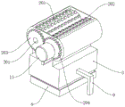
FIG. 1 is a schematic diagram of the overall structure of the present utility model;
FIG. 2 is a schematic view of the whole cross-sectional structure of the present utility model;
FIG. 3 is a schematic view of a part of the brush-removing mechanism according to the present utility model;
fig. 4 is a schematic view showing a partial structure of the pulverizing mechanism of the present utility model.
In the figure: 1. a brushing mechanism; 101. a driven brush roller; 102. a gear b; 103. a driving brush roller; 104. a gear a; 2. a crushing mechanism; 201. a driven pulverizing roller; 202. an active crushing roller; 203. a gear d; 204. a gear c; 3. a housing; 4. a feed hopper; 7. a collection box a; 8. a collection box b; 9. a support leg; 10. a driving motor a; 11. a driving motor b; 12. and (5) a filter plate.
Detailed Description
The utility model is further described below with reference to examples.
In order to make the objects, technical solutions and advantages of the embodiments of the present utility model more apparent, the technical solutions of the embodiments of the present utility model will be clearly and completely described below with reference to the accompanying drawings of the embodiments of the present utility model, and it is apparent that the described embodiments are some, but not all, embodiments of the present utility model, and all other embodiments obtained by persons of ordinary skill in the art without inventive labor based on the described embodiments of the present utility model are included in the scope of protection of the present utility model.
The following examples are illustrative of the present utility model but are not intended to limit the scope of the utility model. The conditions in the examples can be further adjusted according to specific conditions, and simple modifications of the method of the utility model under the premise of the conception of the utility model are all within the scope of the utility model as claimed.
Referring to fig. 1-4, the utility model provides a roller crusher for cement clinker crushing, comprising a housing 3, a feed hopper 4 is arranged at the top end of the housing 3, a brushing mechanism 1 which is positioned under the feed hopper 4 and is communicated with the feed hopper 4 is arranged in the housing 3, a crushing mechanism 2 which is positioned under the brushing mechanism 1 and is communicated with the brushing mechanism 1 is arranged in the housing 3, a driving motor a10 with an output end connected with one outer side end of the brushing mechanism 1 is fixed on the outer side wall of the housing 3, and a driving motor b11 with an output end connected with one outer side end of the crushing mechanism 2 is fixed on the outer side wall of the housing 3; when the cooked cement blocks are crushed, firstly, the cooked cement blocks are put into the feed hopper 4 and fall onto the brushing mechanism 1, the driving motor a10 is started to work, the driving motor a10 drives the brushing mechanism 1 to uniformly and rapidly brush the cooked cement blocks, fine powder particles on the cooked cement blocks are sufficiently and rapidly brushed down, the dust problem during later crushing is reduced, the brushed cooked cement blocks from the brushing mechanism 1 fall onto the crushing mechanism 2 under the action of dead weight, and the driving motor b11 drives the crushing mechanism 2 in the shell 3 to rapidly crush the cooked cement blocks to further refine the cooked cement blocks.
The brushing mechanism 1 comprises a driving brush roller 103 and a driven brush roller 101 which are rotationally connected with the inner side wall of the shell 3, wherein the driving brush roller 103 and the driven brush roller 101 are positioned under the feeding hopper 4, the output end of a driving motor a10 is coaxially fixed with one outer side end of the driving brush roller 103, a gear a104 is coaxially fixed at the outer side end of the driving brush roller 103, a gear b102 coaxially fixed with the outer side end of the driven brush roller 101 is arranged on one side of the gear a104, and the gear a104 and the gear b102 are meshed with each other; when the cooked cement blocks are brushed, firstly, the cooked cement blocks are put into the feed hopper 4 and then fall onto the driven brush roller 101 and the driving brush roller 103, the driving motor a10 is started to work, the driving motor a10 drives the driving brush roller 103 and the gear a104 to rotate, the gear a104 and the gear b102 cooperate to drive the driven brush roller 101 to rotate, the cooked cement blocks are uniformly and rapidly brushed when the driven brush roller 101 and the driving brush roller 103 rotate, fine powder particles on the cooked cement blocks are sufficiently and rapidly brushed, and the dust problem during later-stage crushing is reduced.
The crushing mechanism 2 comprises a driven crushing roller 201 and a driving crushing roller 202 which are rotationally connected with the inner side wall of the shell 3, wherein the driven crushing roller 201 and the driving crushing roller 202 are positioned under the driving brush roller 103 and the driven brush roller 101, the output end of a driving motor b11 is coaxially fixed with one outer side end of the driving crushing roller 202, a gear c204 is coaxially fixed at the outer side end of the driving crushing roller 202, a gear d203 coaxially fixed with the outer side end of the driven crushing roller 201 is arranged at one side of the gear c204, and the gear c204 and the leather gear d203 are meshed with each other; the brushed-off cooked cement blocks on the driven brush roller 101 and the driving brush roller 103 fall onto the driven crushing roller 201 and the driving crushing roller 202 under the action of dead weight, the driving motor b11 drives the driving crushing roller 202 and the gear c204 in the shell 3 to rotate, the gear c204 and the gear d203 cooperate to drive the driven crushing roller 201 to rotate, the driven crushing roller 201 and the driving crushing roller 202 rotate to rapidly crush the cooked cement blocks, and the cooked cement blocks are further refined.
The inner side wall of the shell 3 is fixedly provided with a filter plate 12 positioned below the driven crushing roller 201 and the driving crushing roller 202, the filter plate 12 and the inner side wall of the shell 3 are obliquely arranged, the side surface of the shell 3 is provided with a discharge hole corresponding to the lower end of the filter plate 12, and one side of the discharge hole is provided with a collecting box a7; in specific work, the cooked cement blocks crushed by the driven crushing roller 201 and the driving crushing roller 202 fall onto the filter plate 12, the uncrushed cooked cement blocks slide into the collecting box a7 on the inclined filter plate 12 to be collected intensively, so that the cement blocks are convenient to crush again, and the fully crushed cooked cement is filtered by the filter plate 12 to fall into the collecting box 8 to be collected intensively.
The scheme comprises the following working processes: when the cooked cement blocks are brushed, firstly, the cooked cement blocks are put into the feed hopper 4 and fall onto the driven brush roller 101 and the driving brush roller 103, the driving motor a10 is started to work, the driving motor a10 drives the driving brush roller 103 and the gear a104 to rotate, the gear a104 and the gear b102 cooperate to drive the driven brush roller 101 to rotate, the cooked cement blocks are uniformly and rapidly brushed when the driven brush roller 101 and the driving brush roller 103 rotate, the fine powder particles on the cooked cement blocks are sufficiently and rapidly brushed, the dust problem during later crushing is reduced, the cooked cement blocks brushed from the driven brush roller 101 and the driving brush roller 103 fall onto the driven crushing roller 201 and the driving crushing roller 202 under the action of dead weight, the driving motor b11 drives the driving crushing roller 202 and the gear c204 in the shell 3 to rotate, the gear c204 and the gear d203 cooperate to drive the driven crushing roller 201 to rotate, the driven crushing roller 201 and the driving crushing roller 202 rotate to rapidly crush the cooked cement blocks, the cooked cement blocks are further refined, the cooked cement blocks crushed by the driven crushing roller 201 and the driving crushing roller 202 fall onto the filter plate 12, the un-crushed complete cooked cement blocks slide into the collecting box a7 on the inclined filter plate 12 to be collected in a concentrated manner, and the fully crushed cooked cement is filtered by the filter plate 12 to fall into the collecting box 8 to be collected in a concentrated manner.
The working process can be as follows: the driving motor a10 drives the brushing mechanism 1 to brush out the cooked cement blocks uniformly and rapidly, the fine powder particles on the cooked cement blocks are brushed off sufficiently and rapidly, the dust problem during later-stage crushing is reduced, the cooked cement blocks brushed out from the brushing mechanism 1 fall onto the crushing mechanism 2 under the action of dead weight, and the driving motor b11 drives the crushing mechanism 2 in the shell 3 to perform rapid crushing treatment on the cooked cement blocks, so that the cooked cement blocks are further refined.
The bottom of the shell 3 is provided with a collecting box b8, and the collecting box b8 is positioned right below the filter plate 12; in particular operation, the liquid filtered from the filter plate 12 flows into the collection box b8 for concentrated collection.
The bottom end of the shell 3 is fixedly provided with two supporting legs 9, and the two supporting legs 9 are symmetrically distributed; in specific operation, the symmetrically distributed support legs 9 firmly support the housing 3.
To sum up: the driving motor a10 drives the brushing mechanism 1 to brush out the cooked cement blocks uniformly and rapidly, the fine powder particles on the cooked cement blocks are brushed off sufficiently and rapidly, the dust problem during later-stage crushing is reduced, the cooked cement blocks brushed out from the brushing mechanism 1 fall onto the crushing mechanism 2 under the action of dead weight, and the driving motor b11 drives the crushing mechanism 2 in the shell 3 to perform rapid crushing treatment on the cooked cement blocks, so that the cooked cement blocks are further refined.
Unless otherwise defined, technical or scientific terms used herein shall have the ordinary meaning as understood by one of ordinary skill in the art to which this utility model belongs, the terms "comprising" or "comprises" and the like as used herein shall mean that the element or article preceding the term encompasses the element or article listed after the term and equivalents thereof without excluding other elements or articles, and that the terms "connected" or "connected" and the like shall not be limited to physical or mechanical connections, but shall also include electrical connections, whether direct or indirect, "upper", "lower", "left", "right", etc. are merely intended to indicate relative positional relationships that may also be correspondingly altered when the absolute position of the object being described is altered.
Although embodiments of the present utility model have been shown and described, it will be understood by those skilled in the art that various changes, modifications, substitutions and alterations can be made therein without departing from the principles and spirit of the utility model, the scope of which is defined in the appended claims and their equivalents.
Claims (6)
1. The utility model provides a roll crusher for cement clinker crushing, includes shell (3), its characterized in that, the top of shell (3) is provided with feeder hopper (4), the inside brush mechanism (1) that are located under feeder hopper (4) and are linked together with feeder hopper (4) that are provided with of shell (3), be provided with in shell (3) under brush mechanism (1) and with brush mechanism (1) crushing mechanism (2) that are linked together, the lateral wall of shell (3) is fixed with driving motor a (10) that the output is connected with one lateral end of brush mechanism (1), the lateral wall of shell (3) is fixed with driving motor b (11) that the output is connected with one lateral end of crushing mechanism (2).
2. The roller crusher for cement clinker crushing according to claim 1, wherein the brushing mechanism (1) comprises a driving brush roller (103) and a driven brush roller (101) which are rotatably connected with the inner side wall of the housing (3), the driving brush roller (103) and the driven brush roller (101) are positioned right below the feeding hopper (4), the output end of the driving motor a (10) is coaxially fixed with an outer side end of the driving brush roller (103), a gear a (104) is coaxially fixed with the outer side end of the driving brush roller (103), a gear b (102) coaxially fixed with the outer side end of the driven brush roller (101) is arranged on one side of the gear a (104), and the gear a (104) and the gear b (102) are meshed with each other.
3. The roller crusher for cement clinker crushing according to claim 2, wherein the crushing mechanism (2) comprises a driven crushing roller (201) and a driving crushing roller (202) which are rotatably connected with the inner side wall of the housing (3), the driven crushing roller (201) and the driving crushing roller (202) are positioned right below the driving brush roller (103) and the driven brush roller (101), the output end of the driving motor b (11) is coaxially fixed with an outer side end of the driving crushing roller (202), a gear c (204) is coaxially fixed with the outer side end of the driving crushing roller (202), a gear d (203) coaxially fixed with the outer side end of the driven crushing roller (201) is arranged on one side of the gear c (204), and the gear c (204) and the gear d (203) are mutually meshed.
4. A roller crusher for cement clinker crushing according to claim 3, characterized in that the inner side wall of the housing (3) is fixed with a filter plate (12) positioned below the driven crushing roller (201) and the driving crushing roller (202), the filter plate (12) is obliquely arranged with the inner side wall of the housing (3), the side surface of the housing (3) is provided with a discharge hole corresponding to the lower end of the filter plate (12), and one side of the discharge hole is provided with a collecting box a (7).
5. A roller crusher for cement clinker crushing according to claim 1, characterized in that the bottom of the housing (3) is provided with a collecting box b (8), which collecting box b (8) is located directly below the filter plate (12).
6. The roller crusher for cement clinker crushing according to claim 1, wherein the bottom end of the housing (3) is fixed with two legs (9), and the two legs (9) are symmetrically distributed.
Priority Applications (1)
| Application Number | Priority Date | Filing Date | Title |
|---|---|---|---|
| CN202222977011.8U CN218901977U (en) | 2022-11-09 | 2022-11-09 | Roller crusher for cement clinker crushing |
Applications Claiming Priority (1)
| Application Number | Priority Date | Filing Date | Title |
|---|---|---|---|
| CN202222977011.8U CN218901977U (en) | 2022-11-09 | 2022-11-09 | Roller crusher for cement clinker crushing |
Publications (1)
| Publication Number | Publication Date |
|---|---|
| CN218901977U true CN218901977U (en) | 2023-04-25 |
Family
ID=86046025
Family Applications (1)
| Application Number | Title | Priority Date | Filing Date |
|---|---|---|---|
| CN202222977011.8U Active CN218901977U (en) | 2022-11-09 | 2022-11-09 | Roller crusher for cement clinker crushing |
Country Status (1)
| Country | Link |
|---|---|
| CN (1) | CN218901977U (en) |
-
2022
- 2022-11-09 CN CN202222977011.8U patent/CN218901977U/en active Active
Similar Documents
| Publication | Publication Date | Title |
|---|---|---|
| CN206304851U (en) | A kind of building material crushes feeding device | |
| CN210522761U (en) | Novel industrial silicon is smashing for manufacturing device | |
| CN208695238U (en) | A kind of dry equipment of mushroom bacteria residue crushing dry | |
| CN218901977U (en) | Roller crusher for cement clinker crushing | |
| CN209438739U (en) | A kind of smashing and grinding all-in-one machine of food processing | |
| CN216173009U (en) | Stone crusher capable of refining crushed stones stage by stage | |
| CN111068820A (en) | Environment improvement waste material shredding device | |
| CN211801358U (en) | High-efficient shredding device of solid waste | |
| CN214599306U (en) | High-purity quartz sand production device | |
| CN114177987A (en) | Smashing device for plastic products | |
| CN213996057U (en) | Solid waste recycling treatment device convenient to recycle | |
| CN209735662U (en) | Formula of pushing down food grinder | |
| CN213376858U (en) | Glass fiber waste material breaker | |
| CN112705346A (en) | Industrial waste rapid treatment device | |
| CN114870942A (en) | High efficiency reducing mechanism is used in agricultural product processing | |
| CN206762988U (en) | A kind of petroleum coke breaker | |
| CN206746731U (en) | A kind of organic mat Special grinder for disintegrating | |
| CN219024563U (en) | Novel production device for making bricks by using waste building materials | |
| CN218853853U (en) | Iron and steel rubbing crusher with dust collector | |
| CN109383960A (en) | A kind of intelligent garbage reclaimer for smart home | |
| CN218962892U (en) | Slag treatment device for industrial production | |
| CN215429243U (en) | Chemical raw material grinding device for chemical industry | |
| CN219784912U (en) | Broken processing apparatus of leftover bits | |
| CN217856402U (en) | Novel drum-type graphite grinder | |
| CN203196714U (en) | Lapping-slot-type fine brick material pulverizer |
Legal Events
| Date | Code | Title | Description |
|---|---|---|---|
| GR01 | Patent grant | ||
| GR01 | Patent grant |