CN218891601U - Sheet metal corner polisher with piece adsorption structure - Google Patents
Sheet metal corner polisher with piece adsorption structure Download PDFInfo
- Publication number
- CN218891601U CN218891601U CN202222007812.1U CN202222007812U CN218891601U CN 218891601 U CN218891601 U CN 218891601U CN 202222007812 U CN202222007812 U CN 202222007812U CN 218891601 U CN218891601 U CN 218891601U
- Authority
- CN
- China
- Prior art keywords
- box
- sheet metal
- mounting
- mounting box
- installation
- Prior art date
- Legal status (The legal status is an assumption and is not a legal conclusion. Google has not performed a legal analysis and makes no representation as to the accuracy of the status listed.)
- Active
Links
Images


Classifications
-
- Y—GENERAL TAGGING OF NEW TECHNOLOGICAL DEVELOPMENTS; GENERAL TAGGING OF CROSS-SECTIONAL TECHNOLOGIES SPANNING OVER SEVERAL SECTIONS OF THE IPC; TECHNICAL SUBJECTS COVERED BY FORMER USPC CROSS-REFERENCE ART COLLECTIONS [XRACs] AND DIGESTS
- Y02—TECHNOLOGIES OR APPLICATIONS FOR MITIGATION OR ADAPTATION AGAINST CLIMATE CHANGE
- Y02P—CLIMATE CHANGE MITIGATION TECHNOLOGIES IN THE PRODUCTION OR PROCESSING OF GOODS
- Y02P70/00—Climate change mitigation technologies in the production process for final industrial or consumer products
- Y02P70/10—Greenhouse gas [GHG] capture, material saving, heat recovery or other energy efficient measures, e.g. motor control, characterised by manufacturing processes, e.g. for rolling metal or metal working
Abstract
The utility model is suitable for the related technical field of television backboard, and provides a sheet metal corner polisher with a chip adsorption structure, which comprises: the installation box is internally and fixedly provided with a discharging hopper; the driving wheel is connected to the front end of the motor and arranged in the mounting box, and the right side of the driving wheel is provided with a driven wheel; the support rod is fixedly arranged at the upper end of the blanking hopper in a welding way, and the upper end of the support rod is fixedly connected with a first mounting block; the second installation block is arranged above the first installation block, and the upper end of the second installation block is connected with an adjusting rod; and the magnet plate is fixedly connected with the inner lower end surface of the collecting box. This panel beating corner polisher with piece adsorption structure, the spacing effect of centre gripping is better, and possesses better piece adsorption structure, is convenient for avoid piece to splash, has solved the inconvenient problem of collecting the metal piece that produces in polishing of current sheet metal component polisher.
Description
Technical Field
The utility model relates to the technical field of sheet metal machining, in particular to a sheet metal corner grinding machine with a scrap adsorption structure.
Background
The sheet metal is a comprehensive cold processing technology aiming at a metal sheet, and comprises shearing, punching, cutting, compounding, folding, welding, riveting, splicing, forming and the like, and the sheet metal part is also a common main body material of a television frame, a television backboard and the like, and in order to remove the defects of burrs and the like at the corners of the sheet metal part, polishing equipment is needed to polish, however, the existing sheet metal part polishing equipment has some defects, such as;
for example, a convenient sheet metal sander with a Chinese patent authority publication number of CN212886841U comprises a sander body, wherein the sander body comprises an upper cover plate and a lower cover plate, the upper cover plate comprises a sanding belt, a transmission disc, a high-rotation-speed motor, a first handle, a second handle and a bracket, the bracket is fixedly arranged on the upper cover plate, the first handle is rotatably arranged on the bracket, the sanding belt is fixedly arranged on the transmission disc, the transmission disc is fixedly connected with the high-rotation-speed motor, and a clamping groove is formed in the transmission disc; the lower cover plate can be fixedly connected with the upper cover plate; the utility model improves and upgrades on the basis of the traditional polisher, the design of the double-handle guard can make the double-handle polisher work more safely and efficiently, and the working difficulty and strength of operators are reduced; the multifunctional machine not only can save cost, but also can work efficiently.
However, the prior art solutions described above have the following drawbacks: it does not possess better piece adsorption structure, and inconvenient metal chip that produces in polishing is collected, leads to the piece to splash easily, and then has certain use defect, consequently, we propose a panel beating corner polisher with piece adsorption structure to solve the problem that above-mentioned in put forward.
Disclosure of Invention
The utility model aims to provide a sheet metal corner polisher with a chip adsorption structure, and aims to solve the problems that the existing sheet metal part polisher does not have a good chip adsorption structure, metal chips generated in polishing are inconvenient to collect, and chips are easy to splash.
To achieve the purpose, the utility model adopts the following technical scheme:
a sheet metal corner sander with a chip adsorbing structure, comprising:
the mounting box is fixedly provided with a blanking hopper in the mounting box, the collecting box arranged below the blanking hopper is connected in the mounting box, the front end face of the collecting box is fixedly connected with a pull ring, the rear end face of the mounting box is fixedly provided with a motor, the front end face of the mounting box is hinged with a door plate, and the sheet metal part body is arranged in the mounting box;
the driving wheel is connected to the front end of the motor and arranged in the mounting box, the right side of the driving wheel is provided with a driven wheel, the outer sides of the driving wheel and the driven wheel are connected with a driving belt, and the outer surface of the driving belt is fixedly connected with a frosted belt;
the support rod is fixedly arranged at the upper end of the blanking hopper in a welding way, the upper end of the support rod is fixedly connected with a first installation block, an electric telescopic rod is fixedly arranged on the end face of one side of the first installation block, which is close to the vertical center line of the installation box, and a pressing block is fixedly connected with one end, which is far away from the first installation block, of the electric telescopic rod;
the second installation block is arranged above the first installation block, the upper end of the second installation block is connected with an adjusting rod, and one side of the adjusting rod, which is far away from the vertical center line of the installation box, is provided with a scale rod fixedly connected to the upper end of the second installation block;
the magnet plate, its fixed connection is at the inside lower terminal surface of collecting the box, the left side of magnet plate is provided with fixed connection at the inside filter screen of collecting the box, the left end of collecting the box is connected with the installation pipe of fixed mounting inside the mounting box, and the left end of installation pipe is connected with fixed mounting at the left air exhauster of mounting box.
Preferably, the driving wheel and the driven wheel are both rotatably connected in the installation box, and the driving wheel and the driven wheel are both in meshed connection with the transmission belt.
Preferably, the electric telescopic rod and the pressing block are arranged in a front-back symmetrical mode relative to the vertical center line of the mounting box, and the electric telescopic rod and the pressing block are fixedly mounted on one side end face of the second mounting block, which is close to the vertical center line of the mounting box.
Preferably, the adjusting rod is in threaded connection with the upper end face of the mounting box, and the adjusting rod and the second mounting block are in rotary connection.
Preferably, the scale rod is slidably connected with the upper end surface of the mounting box and plays a role in limiting the second mounting block.
Preferably, the collection box is slidably connected at a position inside the installation box.
The beneficial effects of the utility model are as follows:
1. the sheet metal corner polisher with the chip adsorption structure provided by the utility model has a good clamping and limiting effect and a good chip adsorption structure, is convenient to avoid chip splashing, and solves the problem that the existing sheet metal part polisher is inconvenient to collect metal chips generated in polishing.
2. The sheet metal corner polisher with the scrap adsorption structure is provided with the adjusting rod, the second mounting blocks and the pressing blocks, the height position of the second mounting blocks at the lower end of the adjusting rod is adjusted by rotating the adjusting rod, the scale values at the outer sides of the scale rods are observed, the second mounting blocks at the front side and the rear side are located at the same height position, the pressing blocks are driven to move towards the sheet metal part body by extending of the electric telescopic rod, the sheet metal part body is clamped and fixed, and the clamping and limiting effects are good.
3. The sheet metal corner polisher with the scrap adsorption structure is provided with the mounting box, the door plate and the exhaust fan, and is convenient to prevent scraps from splashing when the sheet metal part body is polished by arranging the mounting box, and the exhaust fan is used for sucking, so that the effect of absorbing dust in the mounting box is enhanced, the practicability is better, and the operation is more convenient.
4. The sheet metal corner polisher with the scrap adsorption structure is provided with the collection box, the magnet plate and the blanking hopper, the driving belt moves on the outer sides of the driving wheel and the driven wheel and polishes the corners of the sheet metal part body, polished scraps fall into the collection box through the blanking hopper to be collected, scrap iron is adsorbed by the magnet plate, the scrap iron collection effect is enhanced, and the problem that the existing sheet metal part polisher is inconvenient to collect metal scraps generated in polishing is solved.
Drawings
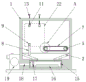
Fig. 1 is a schematic front sectional view of a sheet metal corner polisher with a chip adsorbing structure.
Fig. 2 is a schematic side view cross-sectional structure of a sheet metal corner polisher with a chip adsorbing structure according to the present utility model;
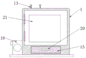
fig. 3 is a schematic front view of a sheet metal corner polishing machine with a chip adsorbing structure according to the present utility model;
FIG. 4 is an enlarged schematic view of the structure of FIG. 1 at A;
fig. 5 is an enlarged schematic view of the structure at B in fig. 2.
In the figure: 1-installing a box; 2-blanking hopper; 3-an electric motor; 4-a driving wheel; 5-driven wheel; 6-a transmission belt; 7-grinding the abrasive belt; 8-supporting rods; 9-a first mounting block; 10-an electric telescopic rod; 11-briquetting; 12-a second mounting block; 13-adjusting the rod; 14-a scale bar; 15-a collection box; 16-magnet plate; 17-a filter screen; 18-mounting a tube; 19-exhaust fan; 20-pull ring; 21-a door panel; 22-sheet metal part body.
Detailed Description
The technical scheme of the utility model is further described below by the specific embodiments with reference to the accompanying drawings.
Referring to fig. 1-5, the present utility model provides a technical solution: a sheet metal corner sander with a chip adsorbing structure, comprising: the inside fixed mounting of install bin 1 has hopper 2 under, and the internally connected of install bin 1 has the collection box 15 that sets up in hopper 2 below under, and the preceding terminal surface fixedly connected with pull ring 20 of collection box 15, the rear end face fixed mounting of install bin 1 has motor 3, and the preceding terminal surface hinge connection of install bin 1 has door plant 21, and the inside of install bin 1 is provided with sheet metal component body 22, action wheel 4 is connected at the front end of motor 3 and sets up in the inside of install bin 1, the right side of action wheel 4 is provided with from driving wheel 5, and the outside of action wheel 4 and from driving wheel 5 is connected with drive belt 6, and the surface fixedly connected with dull polish area 7 of drive belt 6, the upper end welded fixed mounting of hopper 2 has bracing piece 8 down, and the upper end fixedly connected with first installation piece 9 of bracing piece 8, and first installation piece 9 is close to the vertical central line one side terminal surface fixed mounting of install electric telescopic handle 10 of install bin 1.
The electric telescopic rod 10 is kept away from first installation piece 9 one end fixedly connected with briquetting 11, the top at first installation piece 9 is set up to second installation piece 12, the upper end of second installation piece 12 is connected with regulation pole 13, and regulation pole 13 keeps away from the vertical central line one side of installation case 1 and is provided with the scale pole 14 of fixed connection at second installation piece 12 upper end, magnet board 16 fixed connection is at the inside lower terminal surface of collecting box 15, the left side of magnet board 16 is provided with the filter screen 17 of fixed connection in collecting box 15 inside, the left end of collecting box 15 is connected with the installation pipe 18 of fixed mounting in installation case 1, and the left end of installation pipe 18 is connected with the air exhauster 19 of fixed mounting in installation case 1 left side, as shown in fig. 1 and 3, through collecting box 15 sliding connection in the inside below position of installation case 1, hold the pull ring 20 conveniently pull out and collect box 15 and clear up.
When the sheet metal corner polisher with the chip adsorption structure is used, as shown in fig. 3, the door plate 21 is firstly opened, the sheet metal part body 22 is placed into the mounting box 1, and particularly as shown in fig. 1, 2 and 5, as the adjusting rod 13 is in threaded connection with the upper end face of the mounting box 1, and the adjusting rod 13 is in rotary connection with the second mounting block 12, meanwhile, the scale rod 14 is in sliding connection with the upper end face of the mounting box 1 and plays a role of limiting the second mounting block 12, the height position of the second mounting block 12 at the lower end of the adjusting rod 13 is adjusted by rotating the adjusting rod 13, the scale value at the outer side of the scale rod 14 is observed, and the second mounting blocks 12 at the front side and the rear side are located at the same height position.
Specifically, as shown in fig. 1, fig. 2 and fig. 5, the electric telescopic rod 10 stretches to drive the pressing block 11 to move towards the sheet metal part body 22 and clamp and fix the sheet metal part body 22, so that the corner position of the sheet metal part body 22 is in contact with the grinding belt 7, and in combination with the operation shown in fig. 1 and fig. 4, the driving wheel 4 and the driven wheel 5 are both rotationally connected in the installation box 1, and the driving wheel 4 and the driven wheel 5 are both in meshed connection with the driving belt 6, the driving motor 3 drives the driving wheel 4 to rotate, so that the driving belt 6 moves outside the driving wheel 4 and the driven wheel 5 and grinds corners of the sheet metal part body 22, grinding scraps fall into the collection box 15 through the lower hopper 2 to be collected, the suction effect of dust in the installation box 1 is enhanced through the suction of the suction fan 19, the scraps are adsorbed through the magnet plate 16, and the collection effect of the scraps is enhanced, namely the use method of the sheet metal corner grinder with the scraps adsorption structure.
The technical principle of the present utility model is described above in connection with the specific embodiments. The description is made for the purpose of illustrating the general principles of the utility model and should not be taken in any way as limiting the scope of the utility model. Other embodiments of the utility model will be apparent to those skilled in the art from consideration of this specification without undue burden.
Claims (6)
1. Sheet metal corner polisher with piece adsorption structure, its characterized in that: comprising the following steps:
the mounting box is fixedly provided with a blanking hopper in the mounting box, the collecting box arranged below the blanking hopper is connected in the mounting box, the front end face of the collecting box is fixedly connected with a pull ring, the rear end face of the mounting box is fixedly provided with a motor, the front end face of the mounting box is hinged with a door plate, and the sheet metal part body is arranged in the mounting box;
the driving wheel is connected to the front end of the motor and arranged in the mounting box, the right side of the driving wheel is provided with a driven wheel, the outer sides of the driving wheel and the driven wheel are connected with a driving belt, and the outer surface of the driving belt is fixedly connected with a frosted belt;
the support rod is fixedly arranged at the upper end of the blanking hopper in a welding way, the upper end of the support rod is fixedly connected with a first installation block, an electric telescopic rod is fixedly arranged on the end face of one side of the first installation block, which is close to the vertical center line of the installation box, and a pressing block is fixedly connected with one end, which is far away from the first installation block, of the electric telescopic rod;
the second installation block is arranged above the first installation block, the upper end of the second installation block is connected with an adjusting rod, and one side of the adjusting rod, which is far away from the vertical center line of the installation box, is provided with a scale rod fixedly connected to the upper end of the second installation block;
the magnet plate, its fixed connection is at the inside lower terminal surface of collecting the box, the left side of magnet plate is provided with fixed connection at the inside filter screen of collecting the box, the left end of collecting the box is connected with the installation pipe of fixed mounting inside the mounting box, and the left end of installation pipe is connected with fixed mounting at the left air exhauster of mounting box.
2. The sheet metal corner polisher with the scrap adsorbing structure according to claim 1, wherein the driving wheel and the driven wheel are both rotatably connected to the inside of the mounting box, and are both in meshed connection with the driving belt.
3. The sheet metal corner polisher with a scrap adsorbing structure according to claim 1, wherein the electric telescopic rods and the pressing blocks are arranged in a front-back symmetrical mode with respect to a vertical center line of the mounting box, and the electric telescopic rods and the pressing blocks are fixedly mounted on one side end face of the second mounting block, which is close to the vertical center line of the mounting box.
4. The sheet metal corner polisher with the scrap adsorbing structure according to claim 1, wherein the adjusting rod is in threaded connection with the upper end face of the mounting box, and the adjusting rod is in rotary connection with the second mounting block.
5. The sheet metal corner polisher with a chip adsorbing structure according to claim 1, wherein the scale bar is slidably connected to the upper end surface of the mounting box and functions as a limiting second mounting block.
6. The sheet metal corner sander with a chip adsorbing structure according to claim 1, wherein the collecting box is slidably connected at an inner lower position of the mounting box.
Priority Applications (1)
| Application Number | Priority Date | Filing Date | Title |
|---|---|---|---|
| CN202222007812.1U CN218891601U (en) | 2022-08-01 | 2022-08-01 | Sheet metal corner polisher with piece adsorption structure |
Applications Claiming Priority (1)
| Application Number | Priority Date | Filing Date | Title |
|---|---|---|---|
| CN202222007812.1U CN218891601U (en) | 2022-08-01 | 2022-08-01 | Sheet metal corner polisher with piece adsorption structure |
Publications (1)
| Publication Number | Publication Date |
|---|---|
| CN218891601U true CN218891601U (en) | 2023-04-21 |
Family
ID=86000787
Family Applications (1)
| Application Number | Title | Priority Date | Filing Date |
|---|---|---|---|
| CN202222007812.1U Active CN218891601U (en) | 2022-08-01 | 2022-08-01 | Sheet metal corner polisher with piece adsorption structure |
Country Status (1)
| Country | Link |
|---|---|
| CN (1) | CN218891601U (en) |
-
2022
- 2022-08-01 CN CN202222007812.1U patent/CN218891601U/en active Active
Similar Documents
| Publication | Publication Date | Title |
|---|---|---|
| CN210909286U (en) | Terminal surface grinding device of box transformer cabinet curb plate | |
| CN211029436U (en) | Dust removal abrasive band machine | |
| CN218891601U (en) | Sheet metal corner polisher with piece adsorption structure | |
| CN210938548U (en) | Helicopter wing equipment of polishing | |
| CN111618713A (en) | Mechanical polishing equipment | |
| CN209380429U (en) | One kind automatically removing die casting overlap equipment | |
| CN216463718U (en) | Grinding device is used in processing of diamond wheel chip groove | |
| CN211053308U (en) | Burnishing device is used in hardware fitting production | |
| CN217344893U (en) | Graphite grinding device convenient to clean | |
| CN216179187U (en) | Full-automatic shaped glass edging device | |
| CN213765220U (en) | Environment-friendly dust removal equipment for machining mechanical parts | |
| CN218017679U (en) | Novel plane grinding device of belt sander | |
| CN215789163U (en) | Polishing machine with good dust removal effect for machining | |
| CN213165586U (en) | Production line for damping plate | |
| CN213615744U (en) | Burr grinder for machine-building | |
| CN219504401U (en) | Grinding machine for machining center | |
| CN114536187B (en) | Magnetic box cleaning machine and manufacturing method and using method thereof | |
| CN213561696U (en) | Polishing device for machining of allowance-free guider | |
| CN220863704U (en) | Grinding equipment with good dust removal effect | |
| CN213438966U (en) | Grinding device with dust collection structure for metal panel processing | |
| CN217530400U (en) | Burnishing machine of steel production usefulness | |
| CN218251926U (en) | Edging dust collector is used in quartz processing | |
| CN211193334U (en) | Dust protected spherical bearing seat grinding device | |
| CN216759439U (en) | Nail production is with burnishing machine that has sweeps and retrieve structure | |
| CN220740431U (en) | Rotary polishing device for pointed ends for pile machining |
Legal Events
| Date | Code | Title | Description |
|---|---|---|---|
| GR01 | Patent grant | ||
| GR01 | Patent grant |