CN218891266U - Precise screw machining and cutting device - Google Patents
Precise screw machining and cutting device Download PDFInfo
- Publication number
- CN218891266U CN218891266U CN202222610763.0U CN202222610763U CN218891266U CN 218891266 U CN218891266 U CN 218891266U CN 202222610763 U CN202222610763 U CN 202222610763U CN 218891266 U CN218891266 U CN 218891266U
- Authority
- CN
- China
- Prior art keywords
- rod
- screw
- cutting
- moving
- block
- Prior art date
- Legal status (The legal status is an assumption and is not a legal conclusion. Google has not performed a legal analysis and makes no representation as to the accuracy of the status listed.)
- Active
Links
Images


Classifications
-
- Y—GENERAL TAGGING OF NEW TECHNOLOGICAL DEVELOPMENTS; GENERAL TAGGING OF CROSS-SECTIONAL TECHNOLOGIES SPANNING OVER SEVERAL SECTIONS OF THE IPC; TECHNICAL SUBJECTS COVERED BY FORMER USPC CROSS-REFERENCE ART COLLECTIONS [XRACs] AND DIGESTS
- Y02—TECHNOLOGIES OR APPLICATIONS FOR MITIGATION OR ADAPTATION AGAINST CLIMATE CHANGE
- Y02P—CLIMATE CHANGE MITIGATION TECHNOLOGIES IN THE PRODUCTION OR PROCESSING OF GOODS
- Y02P70/00—Climate change mitigation technologies in the production process for final industrial or consumer products
- Y02P70/10—Greenhouse gas [GHG] capture, material saving, heat recovery or other energy efficient measures, e.g. motor control, characterised by manufacturing processes, e.g. for rolling metal or metal working
Abstract
The utility model discloses a precise screw machining and cutting device, which belongs to the technical field of screw machining and comprises a workbench, table legs are arranged at four corners of the bottom surface of the workbench, a clamping device is arranged on the top surface of the left side of the workbench, the clamping device is used for clamping and rotating screws, a die table is arranged on the top surface of the right side of the workbench, different dies can be replaced by the die table, a transverse moving device and a chip processing device are arranged at the bottom of the workbench, the transverse moving device is connected with a longitudinal moving device, the chip processing device is used for collecting chips, a cutting assembly is arranged on the longitudinal moving device, and the transverse moving device and the longitudinal moving device are matched for operation, so that the dies and the cutting screws can be replaced. The clamping device can be used for fixing the screw, the longitudinal moving device and the transverse moving device can be matched to operate so as to replace the die and the cutting screw, and the chip processing device is used for facilitating the cleaning of chips by workers and has high practicability.
Description
Technical Field
The utility model relates to the technical field of screw machining, in particular to a precise screw machining and cutting device.
Background
CN202021589139.1 discloses an automatic nut cutting device for preventing screw displacement, which has good limiting effect on screws, is convenient for preventing screw displacement, and is convenient for clamping different nuts.
The above patent has the following problems:
1. the cutting device can not be integrally machined, can not automatically clamp the screw and replace the cutting die, and has small adaptability.
2. During the processing of the screw, a large amount of fragments can be generated, and the cutting device does not have a device for collecting the fragments, so that the fragments fly in disorder and are difficult to clean by staff.
Disclosure of Invention
The utility model aims to provide a precision screw machining and cutting device which has the advantages that a screw can be fixed through a clamping device, a longitudinal moving device and a transverse moving device can be matched to operate so as to replace a die and the cutting screw, and a chip processing device is used for facilitating a worker to clean chips, so that the precision screw machining and cutting device is high in practicability, and solves the problems in the prior art.
In order to achieve the above purpose, the present utility model provides the following technical solutions: the utility model provides a precision screw processing cutting device, includes the workstation, the table leg is installed in the bottom surface four corners of workstation, is provided with clamping device on the left side top surface of workstation, and clamping device is used for centre gripping and rotatory screw, is provided with the mould platform on the right side top surface of workstation, and the removable different moulds of mould platform are provided with lateral shifting device and piece processing apparatus, and lateral shifting device is connected with longitudinal shifting device, and piece processing apparatus is used for collecting the piece, is provided with cutting assembly on the longitudinal shifting device, and lateral shifting device and longitudinal shifting device cooperation operation can realize changing mould and cutting screw.
Preferably, the clamping device comprises a supporting rod, a rotating motor, a connecting rod, a fixing plate, a limiting groove, air cylinders, connecting rods and clamping blocks, wherein the bottom of the supporting rod is connected with the workbench, the rotating motor is installed on the outer side of the supporting rod, one end of the connecting rod is connected with a shaft of the rotating motor, the connecting rod penetrates out of the supporting rod to be connected with the fixing plate, the limiting groove is formed in the upper side and the lower side of the fixing plate, two groups of air cylinders are respectively arranged at the two ends of the fixing plate, connecting rods penetrating through the limiting groove are connected to the air cylinder rods of the air cylinders, and the connecting rods are connected with the clamping blocks.
Preferably, the lateral shifting device comprises side plates, a variable speed motor, sliding rails, sliding blocks, a shifting frame, a first screw rod and supporting bars, wherein two groups of sliding rails are arranged on the sliding rails, the inner sides of the sliding rails are connected with the outer sides of the working tables, the sliding rails are mutually matched with the sliding blocks and are in sliding connection with the sliding blocks, the outer sides of the sliding blocks are connected with the shifting frame, the side plates are connected with the working tables, the variable speed motor is arranged on the side surfaces of the side plates, the shafts of the variable speed motor are connected with the first screw rod, and the first screw rod penetrates through the shifting frame to be connected with the supporting bars.
Preferably, the longitudinal moving device comprises a fixed seat, a constant speed motor, a second screw rod, a moving block, a transverse frame and guide rods, wherein two fixed seats are arranged, the bottom surfaces of the fixed seats are connected with the top surfaces of two ends of the moving frame, the constant speed motor is arranged on the outer sides of the fixed seats, shafts of the constant speed motor are connected with the second screw rod, the second screw rod penetrates through the top of the moving block to be connected with the fixed seats, the two ends of the transverse frame are connected with the inner sides of the moving frame, the guide rods are arranged in the transverse frame and are parallel to the second screw rod up and down, one ends of the guide rods are connected with one side of the moving frame, and the other ends of the guide rods penetrate through the bottom of the moving block to be connected with the other side of the moving frame.
Preferably, the cutting assembly comprises an electric push rod, a high-speed motor and a connecting block, the side face of the electric push rod is connected with the moving block, the high-speed motor is arranged at the bottom of the electric push rod, a shaft of the high-speed motor is connected with the top face of the connecting block, the bottom face of the connecting block is provided with a groove, and the inner wall of the groove is provided with threads.
Preferably, the die table comprises a limiting hole, cutting blades and limiting blocks, wherein four limiting holes are formed in the top surface of the die table, the cutting blades of four different specifications are placed in the four limiting holes, threads are formed in the lateral peripheral surface of the top of each cutting blade, the threads of each cutting blade are mutually matched with the threads of the connecting block, the bottom surface of each cutting blade is connected with the limiting block, and the limiting blocks are mutually matched with the limiting holes.
Preferably, the piece processing device comprises a fixed cabinet, a drawer, pulleys and handles, wherein the top surfaces of the two sides of the fixed cabinet are connected with the bottom of the workbench, the fixed cabinet is connected with the drawer through the pulleys, and the handles are arranged on the outer sides of the drawer.
Compared with the prior art, the utility model has the following beneficial effects:
1. the precision screw machining and cutting device can fix screws through the clamping device, and the longitudinal moving device and the transverse moving device can be matched to operate so as to replace dies and cutting screws.
2. This accurate screw processing cutting device, through piece processing apparatus, make things convenient for the staff to clear up piece, the practicality is higher.
Drawings
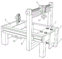
FIG. 1 is a perspective view of a workbench according to the utility model;
FIG. 2 is a perspective view of a lateral mobile device of the present utility model;
FIG. 3 is a perspective view of a longitudinal mobile device according to the present utility model;
FIG. 4 is a perspective view of a clamping device according to the present utility model;
FIG. 5 is a perspective view of a mold table according to the present utility model;
FIG. 6 is a perspective view of a cutting assembly according to the present utility model;
fig. 7 is a perspective view of a debris handling device according to the present utility model.
In the figure: 1. a work table; 2. a table leg; 3. a clamping device; 31. a support rod; 32. a rotating electric machine; 33. a connecting rod; 34. a fixing plate; 35. a limit groove; 36. a cylinder; 37. a connecting rod; 38. a clamping block; 4. a lateral movement device; 41. a side plate; 42. a variable speed motor; 43. a slide rail; 44. a slide block; 45. a moving rack; 46. a first screw rod; 47. a support bar; 5. a longitudinal movement device; 51. a fixing seat; 52. a constant-speed motor; 53. a second screw rod; 54. a moving block; 55. a cross frame; 56. a guide rod; 6. a cutting assembly; 61. an electric push rod; 62. a high-speed motor; 63. a connecting block; 7. a die table; 71. a limiting hole; 72. a cutting blade; 73. a limiting block; 8. a debris handling device; 81. a fixed cabinet; 82. a drawer; 83. a pulley; 84. a handle.
Detailed Description
The following description of the embodiments of the present utility model will be made clearly and completely with reference to the accompanying drawings, in which it is apparent that the embodiments described are only some embodiments of the present utility model, but not all embodiments. All other embodiments, which can be made by those skilled in the art based on the embodiments of the utility model without making any inventive effort, are intended to be within the scope of the utility model.
In order to solve the problems that in the prior art, a cutting device cannot be integrally processed, a screw cannot be automatically clamped, a cutting die cannot be replaced, and the adaptability is small, the following technical scheme is provided, and refer to fig. 1-6;
the utility model provides a precision screw processing cutting device, including workstation 1, table leg 2 is installed to the bottom surface four corners of workstation 1, be provided with clamping device 3 on the left side top surface of workstation 1, clamping device 3 is used for centre gripping and rotatory screw, be provided with mould platform 7 on the right side top surface of workstation 1, the removable different moulds of mould platform 7, the bottom of workstation 1 is provided with lateral shifting device 4 and piece processing device 8, lateral shifting device 4 is connected with longitudinal shifting device 5, piece processing device 8 is used for collecting the piece, be provided with cutting assembly 6 on the longitudinal shifting device 5, lateral shifting device 4 and longitudinal shifting device 5 cooperation operation can realize changing mould and cutting screw;
the clamping device 3 comprises a supporting rod 31, a rotating motor 32, a connecting rod 33, a fixing plate 34, a limiting groove 35, air cylinders 36, connecting rods 37 and clamping blocks 38, wherein the bottom of the supporting rod 31 is connected with the workbench 1, the rotating motor 32 is installed on the outer side of the supporting rod 31, one end of the connecting rod 33 is connected with a shaft of the rotating motor 32, the connecting rod 33 penetrates out of the supporting rod 31 to be connected with the fixing plate 34, the limiting groove 35 is formed in the upper side and the lower side of the fixing plate 34, two groups of air cylinders 36 are respectively arranged at the two ends of the fixing plate 34, the connecting rods 37 penetrating through the limiting groove 35 are connected to the air cylinder rods of the air cylinders 36, and the connecting rods 37 are connected with the clamping blocks 38
Specifically, the staff puts into grip block 38 with the screw pole that needs processing earlier, makes two grip blocks 38 be close to each other through the drive of cylinder 36, and the cylinder pole of cylinder 36 is in spacing inslot 35 removal, and the screw pole is cliied to grip block 38 at last, through rotary motor 32 drive, makes fixed plate 34 rotatory, and fixed plate 34 can drive grip block 38 rotation to make the screw rotatory, conveniently cooperate the going on of cutting work.
The transverse moving device 4 comprises side plates 41, a variable speed motor 42, sliding rails 43, sliding blocks 44, a moving frame 45, a first screw rod 46 and supporting bars 47, wherein two groups of sliding rails 43 are arranged, the inner sides of the sliding rails 43 are connected with the outer sides of the working tables 1, the sliding rails 43 are mutually matched with the sliding blocks 44 and are in sliding connection, the outer sides of the sliding blocks 44 are connected with the moving frame 45, the side plates 41 are connected with the working tables 1, variable speed motors 42 are arranged on the side surfaces of the side plates 41, shafts of the variable speed motors 42 are connected with the first screw rods 46, and the first screw rods 46 penetrate through the moving frame 45 and are connected with the supporting bars 47.
Specifically, the first screw rod 46 is driven to rotate by the rotation of the variable speed motor 42, the moving frame 45 is in threaded connection with the first screw rod 46, the first screw rod 46 rotates to enable the moving frame 45 to move on the first screw rod 46, and meanwhile, the sliding block 44 moves in the sliding rail 43 to play a role in supporting the moving frame 45.
The longitudinal moving device 5 comprises a fixed seat 51, a constant speed motor 52, a second screw rod 53, a moving block 54, a transverse frame 55 and guide rods 56, wherein two fixed seats 51 are arranged, the bottom surface of each fixed seat 51 is connected with the top surfaces of two ends of the moving frame 45, the constant speed motor 52 is arranged on the outer side of each fixed seat 51, the shaft of each constant speed motor 52 is connected with the corresponding second screw rod 53, the second screw rod 53 penetrates through the top of each moving block 54 to be connected with the corresponding fixed seat 51, two ends of each transverse frame 55 are connected with the inner side of the corresponding moving frame 45, the guide rods 56 are arranged in the transverse frame 55 and are parallel to the corresponding second screw rods 53 up and down, one end of each guide rod 56 is connected with one side of the corresponding moving frame 45, and the other end of each guide rod 56 penetrates through the bottom of the corresponding moving block 54 to be connected with the other side of the corresponding moving frame 45.
Specifically, the moving frame 45 drives the longitudinal moving device 5 to move while moving, the second screw rod 53 is driven to rotate by the rotation of the uniform motor 52, the moving block 54 is in threaded connection with the second screw rod 53, the top of the moving block 54 moves on the second screw rod 53 due to the rotation of the second screw rod 53, and meanwhile, the bottom of the moving block 54 moves on the guide rod 56.
The cutting assembly 6 comprises an electric push rod 61, a high-speed motor 62 and a connecting block 63, wherein the side surface of the electric push rod 61 is connected with the moving block 54, the high-speed motor 62 is arranged at the bottom of the electric push rod 61, the shaft of the high-speed motor 62 is connected with the top surface of the connecting block 63, the bottom surface of the connecting block 63 is provided with a groove, and the inner wall of the groove is provided with threads.
Specifically, the movement of the moving block 54 drives the cutting assembly 6 to move together, under the cooperation of the transverse moving device 4 and the longitudinal moving device 5, the cutting assembly 6 is moved to be right above the screw to be processed, the electric push rod 61 pushes the cutting blade 72 downwards to be attached to the lateral peripheral surface of the screw, the high-speed motor 62 drives the cutting blade 72 to cut the screw, and meanwhile, the rotating motor 32 in the clamping device 3 drives the screw to rotate, so that the working efficiency is improved.
The die table 7 comprises limit holes 71, cutting blades 72 and limit blocks 73, four limit holes 71 are formed in the top surface of the die table 7, the cutting blades 72 with four different specifications are placed in the four limit holes 71, threads are arranged on the lateral peripheral surface of the top of the cutting blades 72, the threads of the cutting blades 72 are mutually matched with the threads of the connecting block 63, the bottom surface of the cutting blades 72 is connected with the limit blocks 73, and the limit blocks 73 are mutually matched with the limit holes 71.
Specifically, through the cooperation operation of lateral shifting device 4 and vertical shifting device 5, remove cutting assembly 6 directly over the mould platform 7, make connecting block 63 and cutting sword 72 top surface laminating through electric putter 61, rotate connecting block 63 through high-speed motor 62, make connecting block 63 and cutting sword 72 screw thread combination, stopper 73 plays the effect of spacing cutting sword 72, has saved artifical manual change mould cutter like this, has increased production efficiency, has improved workman's working environment simultaneously.
In order to solve the problems that in the prior art, a large amount of scraps are generated in the processing process of the screw, and the scraps are scattered due to the fact that a cutting device does not have a device for collecting the scraps, and the scraps are difficult to clean by staff, the following technical scheme is provided, and refer to fig. 1-4;
the chip treatment device 8 comprises a fixed cabinet 81, a drawer 82, a pulley 83 and a handle 84, wherein the top surfaces of the two sides of the fixed cabinet 81 are connected with the bottom of the workbench 1, the fixed cabinet 81 is connected with the drawer 82 through the pulley 83, and the handle 84 is arranged on the outer side of the drawer 82
Specifically, in the screw machining process, scraps can be scattered into the drawer 82 of the fixed cabinet 81, after machining is finished, a worker pulls the drawer 82 out of the fixed cabinet 81 by pulling the handle 84, and therefore the worker can conveniently clean scraps of the drawer 82.
Working principle: in the precision screw machining cutting device, a worker firstly puts a screw rod to be machined into a clamping block 38, drives the two clamping blocks 38 to mutually approach through a cylinder 36, the cylinder rod of the cylinder 36 moves in a limiting groove 35, finally the clamping block 38 clamps the screw rod, drives a fixed plate 34 to rotate through a rotating motor 32, the fixed plate 34 drives the clamping block 38 to rotate, thereby rotating the screw, facilitating the progress of the matched cutting work, driving a first screw rod 46 to rotate through the rotation of a variable speed motor 42, a moving frame 45 is in threaded connection with the first screw rod 46, the first screw rod 46 rotates to enable the moving frame 45 to move on the first screw rod 46, the moving frame 45 simultaneously drives a longitudinal moving device 5 to move, drives a second screw rod 53 to rotate through the rotation of a uniform speed motor 52, the moving block 54 is in threaded connection with the second screw rod 53, the top of the moving block 54 moves on the second screw rod 53 when the second screw rod 53 rotates, the moving block 54 moves to drive the cutting assembly 6 to move together, under the cooperation of the transverse moving device 4 and the longitudinal moving device 5, the cutting assembly 6 moves to be right above a screw to be processed, the cutting blade 72 is attached to the side peripheral surface of the screw by pushing downwards through the electric push rod 61, the screw is cut by driving the cutting blade 72 through the high-speed motor 62, the cutting assembly 6 moves to be right above the die table 7 under the cooperation of the transverse moving device 4 and the longitudinal moving device 5, the connecting block 63 is attached to the top surface of the cutting blade 72 through the electric push rod 61, the connecting block 63 is combined with the cutting blade 72 through the rotation of the high-speed motor 62, chips are scattered into the drawer 82 of the fixed cabinet 81 during the processing of the screw, after the processing is finished, a worker pulls the drawer 82 out of the stationary cabinet 81 by pulling the handle 84, facilitating the cleaning of the drawer 82 from debris.
It is noted that relational terms such as first and second, and the like are used solely to distinguish one entity or action from another entity or action without necessarily requiring or implying any actual such relationship or order between such entities or actions. Moreover, the terms "comprises," "comprising," or any other variation thereof, are intended to cover a non-exclusive inclusion, such that a process, method, article, or apparatus that comprises a list of elements does not include only those elements but may include other elements not expressly listed or inherent to such process, method, article, or apparatus.
Although embodiments of the present utility model have been shown and described, it will be understood by those skilled in the art that various changes, modifications, substitutions and alterations can be made therein without departing from the principles and spirit of the utility model, the scope of which is defined in the appended claims and their equivalents.
Claims (7)
1. The utility model provides a precision screw processing cutting device, includes workstation (1), its characterized in that: table legs (2) are installed at four corners of the bottom surface of the workbench (1), clamping devices (3) are arranged on the top surface of the left side of the workbench (1), the clamping devices (3) are used for clamping and rotating screws, a die table (7) is arranged on the top surface of the right side of the workbench (1), different dies can be replaced by the die table (7), a transverse moving device (4) and a chip processing device (8) are arranged at the bottom of the workbench (1), the transverse moving device (4) is connected with the longitudinal moving device (5), the chip processing device (8) is used for collecting chips, a cutting assembly (6) is arranged on the longitudinal moving device (5), and the transverse moving device (4) and the longitudinal moving device (5) are matched to operate so that the dies and the cutting screws can be replaced.
2. The precision screw machining cutting device according to claim 1, wherein the clamping device (3) comprises a supporting rod (31), a rotating motor (32), a connecting rod (33), a fixing plate (34), a limiting groove (35), an air cylinder (36), a connecting rod (37) and a clamping block (38), the bottom of the supporting rod (31) is connected with the workbench (1), the rotating motor (32) is installed on the outer side of the supporting rod (31), one end of the connecting rod (33) is connected with a shaft of the rotating motor (32), the connecting rod (33) penetrates out of the supporting rod (31) to be connected with the fixing plate (34), the limiting groove (35) is formed in the upper side and the lower side of the fixing plate (34), two groups of air cylinders (36) are respectively arranged at two ends of the fixing plate (34), the connecting rod (37) penetrating through the limiting groove (35) is connected with the air cylinder rod of the air cylinder (36), and the connecting rod (37) is connected with the clamping block (38).
3. The precision screw machining cutting device according to claim 1, wherein the transverse moving device (4) comprises a side plate (41), a variable speed motor (42), a sliding rail (43), a sliding block (44), a moving frame (45), a first screw rod (46) and a supporting bar (47), the sliding rail (43) is provided with two groups, the inner side of the sliding rail (43) is connected with the outer side of the workbench (1), the sliding rail (43) is mutually matched and slidingly connected with the sliding block (44), the outer side of the sliding block (44) is connected with the moving frame (45), the side plate (41) is connected with the workbench (1), the side surface of the side plate (41) is provided with the variable speed motor (42), the shaft of the variable speed motor (42) is connected with the first screw rod (46), and the first screw rod (46) penetrates through the moving frame (45) to be connected with the supporting bar (47).
4. The precision screw machining cutting device according to claim 1, wherein the longitudinal moving device (5) comprises a fixed seat (51), a constant speed motor (52), a second screw rod (53), a moving block (54), a transverse frame (55) and guide rods (56), the fixed seat (51) is provided with two, the bottom surface of the fixed seat (51) is connected with the top surfaces at two ends of the moving frame (45), the constant speed motor (52) is arranged on the outer side of the fixed seat (51), a shaft of the constant speed motor (52) is connected with the second screw rod (53), the second screw rod (53) penetrates through the top of the moving block (54) to be connected with the fixed seat (51), two ends of the transverse frame (55) are connected with the inner side of the moving frame (45), guide rods (56) are arranged in the transverse frame (55) and are parallel up and down, one end of each guide rod (56) is connected with one side of the moving frame (45), and the other end of each guide rod penetrates through the bottom of the moving block (54) to be connected with the other side of the moving frame (45).
5. The precise screw machining cutting device according to claim 1, wherein the cutting assembly (6) comprises an electric push rod (61), a high-speed motor (62) and a connecting block (63), the side surface of the electric push rod (61) is connected with the moving block (54), the high-speed motor (62) is arranged at the bottom of the electric push rod (61), the shaft of the high-speed motor (62) is connected with the top surface of the connecting block (63), the bottom surface of the connecting block (63) is provided with a groove, and the inner wall of the groove is provided with threads.
6. The precise screw machining cutting device according to claim 1, wherein the die table (7) comprises a limiting hole (71), cutting blades (72) and limiting blocks (73), four limiting holes (71) are formed in the top surface of the die table (7), the cutting blades (72) of four different specifications are placed in the four limiting holes (71), threads are formed in the top lateral peripheral surface of the cutting blades (72), the threads of the cutting blades (72) are mutually matched with the threads of the connecting block (63), the bottom surface of the cutting blades (72) is connected with the limiting blocks (73), and the limiting blocks (73) are mutually matched with the limiting holes (71).
7. The precision screw machining cutting device according to claim 1, wherein the chip handling apparatus (8) comprises a stationary cabinet (81), a drawer (82), pulleys (83) and a handle (84), both side top surfaces of the stationary cabinet (81) are connected with the bottom of the table (1), the stationary cabinet (81) is connected with the drawer (82) through the pulleys (83), and the handle (84) is provided on the outer side of the drawer (82).
Priority Applications (1)
| Application Number | Priority Date | Filing Date | Title |
|---|---|---|---|
| CN202222610763.0U CN218891266U (en) | 2022-09-30 | 2022-09-30 | Precise screw machining and cutting device |
Applications Claiming Priority (1)
| Application Number | Priority Date | Filing Date | Title |
|---|---|---|---|
| CN202222610763.0U CN218891266U (en) | 2022-09-30 | 2022-09-30 | Precise screw machining and cutting device |
Publications (1)
| Publication Number | Publication Date |
|---|---|
| CN218891266U true CN218891266U (en) | 2023-04-21 |
Family
ID=86001374
Family Applications (1)
| Application Number | Title | Priority Date | Filing Date |
|---|---|---|---|
| CN202222610763.0U Active CN218891266U (en) | 2022-09-30 | 2022-09-30 | Precise screw machining and cutting device |
Country Status (1)
| Country | Link |
|---|---|
| CN (1) | CN218891266U (en) |
-
2022
- 2022-09-30 CN CN202222610763.0U patent/CN218891266U/en active Active
Similar Documents
| Publication | Publication Date | Title |
|---|---|---|
| CN108115200A (en) | Doorframe plate synchronous cutting equipment | |
| CN112428060A (en) | Chamfering device for machining | |
| CN212823082U (en) | Bar cutting device for machining convenient to use | |
| CN218891266U (en) | Precise screw machining and cutting device | |
| CN210524011U (en) | Sawing machine tool for aluminum-plastic section doors and windows | |
| CN213730217U (en) | Positioning fixture structure for engraving and milling machine | |
| CN115194496A (en) | High-precision vertical lathe workbench and machining method thereof | |
| CN212398315U (en) | Novel saw cutting machine tool | |
| CN210651093U (en) | Double-end corner sawing machine | |
| CN220718820U (en) | Automatic grinding device of light curve grinding machine | |
| CN215280053U (en) | Die forging fork type chain processing is with raw materials device that cuts | |
| CN215703007U (en) | Stone cutting machine | |
| CN110756899A (en) | Numerical control band saw machine convenient to adjust saw blade rate of tension | |
| CN219966546U (en) | Engine cylinder block mills a device | |
| CN220863523U (en) | Automatic change burr remove device for machine-building | |
| CN220073804U (en) | Pipe orifice trimmer for metal hose machining | |
| CN216938670U (en) | Double-station automatic cutting equipment | |
| CN220362028U (en) | Numerical control rope groove milling device with laser ranging function | |
| CN219212460U (en) | Double-sided multi-station milling machine | |
| CN217493724U (en) | Burr polishing equipment for plastic part production | |
| CN218903679U (en) | Punching equipment for processing die steel plate | |
| CN216299581U (en) | Automatic tool changing mechanism of alternating suitable for bamboo timber subdivision | |
| CN220127729U (en) | Vertical pull-up broaching machine bedstead | |
| CN220880373U (en) | Combined thread rolling pressing plate | |
| CN216370504U (en) | All-in-one is handled to surface fluting for machining |
Legal Events
| Date | Code | Title | Description |
|---|---|---|---|
| GR01 | Patent grant | ||
| GR01 | Patent grant | ||
| TR01 | Transfer of patent right |
Effective date of registration: 20230817 Address after: 516000 qiuchanglinghu Industrial Zone, Huiyang District, Huizhou City, Guangdong Province Patentee after: Huizhou Huili Hardware Products Co.,Ltd. Address before: 516000 Gaowu Section, Dongfeng Village, Xinwei Town, Huiyang District, Huizhou City, Guangdong Province Patentee before: Huizhou Xinling Industrial Co.,Ltd. |
|
| TR01 | Transfer of patent right |