CN218861357U - Prefabricated inverted arch bridge girder erection machine - Google Patents
Prefabricated inverted arch bridge girder erection machine Download PDFInfo
- Publication number
- CN218861357U CN218861357U CN202223151091.8U CN202223151091U CN218861357U CN 218861357 U CN218861357 U CN 218861357U CN 202223151091 U CN202223151091 U CN 202223151091U CN 218861357 U CN218861357 U CN 218861357U
- Authority
- CN
- China
- Prior art keywords
- inverted arch
- hoisting
- prefabricated inverted
- prefabricated
- bridge
- Prior art date
- Legal status (The legal status is an assumption and is not a legal conclusion. Google has not performed a legal analysis and makes no representation as to the accuracy of the status listed.)
- Active
Links
Images
Landscapes
- Bridges Or Land Bridges (AREA)
Abstract
The utility model provides a prefabricated invert frame bridge crane, includes hoisting support, can be on hoisting support prefabricated invert hoisting trolley and the pontic of arranging along the fore-and-aft direction that removes, pontic front end and hoisting support front end hinge, are equipped with the swing driving piece that is used for driving the pontic luffing motion on hoisting support. The using method comprises the following steps of S1, before the prefabricated inverted arch constructed in the previous process fails to bear the load, using the bridge body as a vehicle passing channel; s2, transporting the prefabricated inverted arch to be hoisted to the position below the rear end of the hoisting support by a transport vehicle, and driving the bridge body to swing upwards to give way to the next working procedure construction position by a swing driving piece; s3, hoisting each prefabricated inverted arch to be hoisted to a corresponding installation position by the prefabricated inverted arch hoisting trolley; and S4, driving the bridge body to swing downwards until the rear end of the bridge body is erected on the prefabricated inverted arch capable of bearing, and using the bridge body as a vehicle passing channel. The utility model discloses simple structure can once only install the prefabricated inverted arch of polylith, and the vehicle can be in time current, has improved the efficiency of construction.
Description
Technical Field
The utility model relates to a tunnel construction equipment especially relates to a prefabricated inverted arch bridge girder erection machine.
Background
At present, the scheme is assembled to prefabricated inverted arch in the tunnel, mainly adopts cantilever type equipment of lifting by crane, and the defect that this type of equipment exists lies in: the installation polylith once only to after the prefabricated inverted arch is assembled because the below need carry out slip casting and other constructions, lead to the vehicle can't be in time current, in the tunnel excavation construction, if can in time satisfy current, can improve the efficiency of construction by a wide margin.
SUMMERY OF THE UTILITY MODEL
The to-be-solved technical problem of the utility model is to overcome prior art not enough, provide a simple structure, can once only install the prefabricated invert of polylith, the vehicle can be in time current, is favorable to improving efficiency of construction's prefabricated invert bridging machine.
The utility model discloses further provide an application method of above-mentioned prefabricated inverted arch frame bridge crane.
In order to solve the technical problem, the utility model discloses a following technical scheme:
the utility model provides a prefabricated invert frame bridge crane, includes hoisting support, can be on hoisting support prefabricated invert hoisting trolley and the pontic of arranging along the fore-and-aft direction, the pontic front end with the hoisting support front end is articulated, be equipped with on the hoisting support and be used for driving the swinging driving spare of pontic luffing motion.
As a further improvement of the above technical solution: the front end of the hoisting support is provided with telescopic support legs, and the front end of the bridge body is hinged with the lower parts of the telescopic support legs.
As a further improvement of the above technical solution: and two ends of the hoisting support are provided with walking mechanisms.
As a further improvement of the technical scheme: the prefabricated inverted arch hoisting trolley comprises a longitudinal moving mechanism arranged on the longitudinal guide rail, a transverse guide rail arranged on the longitudinal moving mechanism, a transverse moving mechanism arranged on the transverse guide rail and a hoisting component arranged on the transverse moving mechanism.
As a further improvement of the above technical solution: the hoisting part is rotatably connected with the transverse moving mechanism.
As a further improvement of the above technical solution: the front end of the hoisting support is also provided with a downward-inclined transition bridge, and the rear end of the transition bridge is butted with the front end of the bridge body.
As a further improvement of the technical scheme: the transition bridge is hinged with the hoisting support.
As a further improvement of the technical scheme: the bridge body comprises at least two sections, and the adjacent sections are hinged and provided with folding driving pieces.
As a further improvement of the above technical solution: the bridge body comprises at least two subsections, and adjacent subsections are in sliding butt joint and are provided with folding driving parts.
The use method of the prefabricated inverted arch bridge girder erection machine comprises the following steps:
s1, before the prefabricated inverted arch constructed in the previous procedure cannot bear the load, the bridge body is used as a vehicle passing channel;
s2, transporting the prefabricated inverted arch to be hoisted to the position below the rear end of the hoisting support by a transport vehicle, and driving the bridge body to swing upwards to give way to the next working procedure construction position by a swing driving piece;
s3, hoisting each prefabricated inverted arch to be hoisted to a corresponding installation position by the prefabricated inverted arch hoisting trolley;
and S4, driving the bridge body to swing downwards until the rear end of the bridge body is erected on a prefabricated inverted arch capable of bearing, and using the bridge body as a vehicle passing channel.
Compared with the prior art, the utility model has the advantages of: the utility model discloses a prefabricated inverted arch bridge girder erection machine, be equipped with prefabricated inverted arch hoisting trolley on the hoisting support, and hoisting support front end and pontic front end hinge, and through swing driving piece drive pontic luffing motion, pontic luffing motion lets out next process construction position, prefabricated inverted arch hoisting trolley can hoist whole prefabricated inverted arches of current process to waiting to install the position from the haulage vehicle this moment, follow-up by constructor completion installation; before the prefabricated inverted arch fails to bear the weight, the bridge body swings downwards to overlap the rear end of the bridge body on the prefabricated inverted arch capable of bearing the weight, the vehicle can pass through the bridge body in the state, the structure is simple, the timely passing requirement of the vehicle can be met, and therefore the construction efficiency is greatly improved.
The utility model discloses a use method of prefabricated inverted arch bridge girder erection machine, after the bridge body swings upwards and gives way to the next process construction site, all prefabricated inverted arches of the current process can be hoisted to the position to be installed from the transport vehicle, and then the installation is completed by constructors; before the bearing is failed to the prefabricated inverted arch, the bridge body swings downwards to lap the rear end on the prefabricated inverted arch capable of bearing, the vehicle can pass through the bridge body in the state, the operation is simple, the timely passing requirement of the vehicle can be met, and therefore the construction efficiency is greatly improved.
Drawings
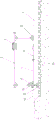
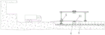
Fig. 1 is a schematic structural diagram of the side surface of the prefabricated inverted arch bridge girder erection machine of the utility model.
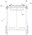
Fig. 2 is the structural schematic diagram of the end face of the prefabricated inverted arch bridge girder erection machine of the utility model.
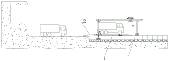
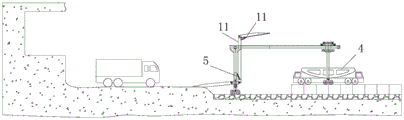
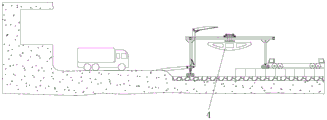
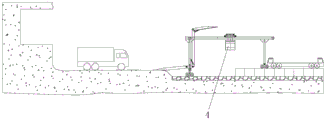
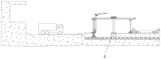
Fig. 3a to 3f are schematic flow charts of the using method of the prefabricated inverted arch bridge girder erection machine of the present invention.
The reference numerals in the figures denote: 1. a bridge body; 11. segmenting; 12. a transition bridge; 13. a folding drive member; 2. prefabricating an inverted arch hoisting trolley; 21. a longitudinal moving mechanism; 22. a transverse guide rail; 23. a traversing mechanism; 24. hoisting the component; 3. hoisting a support; 31. a telescopic leg; 32. a traveling mechanism; 33. a longitudinal guide rail; 4. prefabricating an inverted arch; 5. the driving member is swung.
Detailed Description
As used in this section and in the claims, the terms "a," "an," "the," and/or "the" are not intended to be inclusive in the singular, but may include the plural unless the context clearly dictates otherwise. The use of "first," "second," and similar terms in this section do not denote any order, quantity, or importance, but rather the terms are used to distinguish one element from another. Likewise, the word "comprising" or "comprises", and the like, means that the element or item listed before the word covers the element or item listed after the word and its equivalents, but does not exclude other elements or items. The terms "connected" or "coupled" and the like are not restricted to physical or mechanical connections, but may include electrical connections, whether direct or indirect.
The invention is described in further detail below with reference to the drawings and specific examples.
Example one
As shown in fig. 1 and 2, the prefabricated inverted arch bridge girder erection machine of the embodiment includes a hoisting support 3, a prefabricated inverted arch hoisting trolley 2 capable of moving on the hoisting support 3, and a bridge body 1 arranged along the front-rear direction, wherein the front end of the bridge body 1 is hinged to the lower portion of the front end of the hoisting support 3, and a swing driving member 5 for driving the bridge body 1 to swing up and down is arranged on the hoisting support 3. It should be noted that the longitudinal direction and the front-back direction are the length direction of the tunnel, correspondingly, the transverse direction and the left-right direction are the width direction of the tunnel, one end of the bridge body 1 close to the excavation area is the front end, and correspondingly, one end of the bridge body 1 close to the installed prefabricated inverted arch 4 is the rear end. The hoisting mode of the prefabricated inverted arch 4 by the prefabricated inverted arch hoisting trolley 2 is the same as that of the existing hoisting mode, for example, a lifting hook is matched with a hanging strip, a steel cable and the like, and the detailed description is omitted. The swing driving member 5 can be various, such as an oil cylinder, an electric push rod or a steel cable, and the like, and can drive the bridge body 1 to swing up and down, which is not described in detail.
According to the prefabricated inverted arch bridge girder erection machine, a prefabricated inverted arch hoisting trolley 2 is arranged on a hoisting support 3, the lower part of the front end of the hoisting support is hinged with the front end of a bridge body 1, the bridge body 1 is driven by a swing driving piece 5 to swing up and down, the bridge body 1 swings upwards to give way to the construction position of the next process, at the moment, the prefabricated inverted arch hoisting trolley 2 can hoist all prefabricated inverted arches 4 of the current process from a transport vehicle to the position to be installed, and then the prefabricated inverted arch bridge girder erection machine is installed by constructors; before prefabricated inverted arch 4 can not bear the weight of, pontic 1 downswing with the rear end overlap joint on prefabricated inverted arch 4 that can bear the weight of, the vehicle can pass from pontic 1 under this kind of state, simple structure can satisfy the timely current needs of vehicle to improve the efficiency of construction greatly.
Further, in this embodiment, the front end of the hoisting support 3 is provided with a telescopic leg 31, and the front end of the bridge body 1 is hinged to the lower part of the telescopic leg 31. The front end adopts flexible landing leg 31, can adapt to the circumstances such as the unevenness of ground, overexcavation or owe to dig, simple structure, reasonable. The telescopic supporting leg 31 may be in various telescopic modes, for example, it includes a multi-section sleeve, a sliding rail, etc., two adjacent sections are sleeved and slidably butted, and are driven by an oil cylinder, an electric push rod, etc. to extend and retract, which is not described again.
Further, in this embodiment, the hoisting bracket 3 is provided with traveling mechanisms 32 at two ends. After the construction of the current process is completed, the traveling mechanism 32 can autonomously drive the hoisting support 3 to travel forwards, and the use is more convenient. Wherein the running gear 32 can be, for example, a rubber wheel, a wheel box and/or a crawler mechanism, etc., and will not be described in detail.
Further, in this embodiment, the hoisting support 3 is provided with a longitudinal guide rail 33, and the prefabricated inverted arch hoisting trolley 2 includes a longitudinal moving mechanism 21 disposed on the longitudinal guide rail 33, a transverse guide rail 22 disposed on the longitudinal moving mechanism 21, a transverse moving mechanism 23 disposed on the transverse guide rail 22, and a hoisting component 24 disposed on the transverse moving mechanism 23. When the transverse moving mechanism 23 moves along the transverse guide rail 22, the hoisting component 24 and the hoisted prefabricated inverted arch 4 can be driven to move transversely to adjust the position, and correspondingly, when the longitudinal moving mechanism 21 moves along the longitudinal guide rail 33, the transverse guide rail 22, the transverse moving mechanism 23, the hoisting component 24 and the hoisted prefabricated inverted arch 4 can be driven to move longitudinally to adjust the position, so that the prefabricated inverted arch 4 can be accurately hoisted to the corresponding installation position from a transport vehicle.
Furthermore, in this embodiment, the hoisting component 24 is rotatably connected to the traversing mechanism 23, specifically, the hoisting component 24 or the prefabricated inverted arch 4 to be hoisted may be manually rotated by a constructor, and the hoisting component 24 may also be actively driven to rotate by a driving component (e.g., a rotary cylinder, a motor, etc.). When the placing direction of the prefabricated inverted arch 4 on the transport vehicle is vertical to the installing direction, the prefabricated inverted arch can rotate after being lifted, the subsequent installation is convenient, and the structure is simple and reasonable.
Further, in this embodiment, the front end of the hoisting support 3 is further provided with a downward-inclined transition bridge 12, the rear end of the transition bridge 12 is butted with the front end of the bridge body 1, the height difference between the bridge body 1 and the front end excavation area can be eliminated by the transition bridge 12, vehicles can smoothly go up and down the bridge body 1, and the structure is simple and reliable.
Furthermore, in this embodiment, the transition bridge 12 is hinged to the hoisting support 3, so that on one hand, the inclination angle of the transition bridge 12 is convenient to adjust, and the adaptability is improved, and on the other hand, when the equipment needs to move forward to the next process, the transition bridge 12 can be lifted upwards, so that the interference is avoided, and the structure is simple and reasonable, and the use is more convenient.
Further, in the present embodiment, the bridge body 1 includes at least two segments 11, and a folding driving member 13 (such as an oil cylinder, an air cylinder, or an electric push rod) is hinged between adjacent segments 11. Because the height of the tunnel is limited, in order to meet the length requirement of a construction interval, the length of the bridge body 1 may be larger than the height of the tunnel, and in this case, the bridge body 1 cannot swing upwards to a vertical state, and the hoisting of the prefabricated inverted arch 4 may be affected. Therefore, the bridge body 1 of the embodiment can be folded in a rotating manner under the action of the folding driving piece 13, so that the aim of swinging to a vertical state is fulfilled, and the structure is simple and effective.
Certainly, in other embodiments, the segments 11 of the bridge body 1 can also be in sliding butt joint, and can be folded in a sliding manner under the action of the folding driving element 13, so that the aim of swinging to a vertical state can be achieved, and the structure is simple and effective.
Example two
Fig. 3 shows an embodiment of the utility model of a method for using the prefabricated inverted arch bridge girder erection machine, the method for using the prefabricated inverted arch bridge girder erection machine of this embodiment, including the following steps:
s1, before the prefabricated inverted arch 4 constructed in the previous process is not supported, the bridge body 1 is used as a vehicle passing channel, specifically referring to fig. 3a, at the moment, the front end of a transition bridge 12 is erected in a front end excavation area, and the rear end of the bridge body 1 is erected on the prefabricated inverted arch 4 capable of supporting;
s2, transporting the prefabricated inverted arch 4 to be hoisted to the position below the rear end of the hoisting support 3 by a transport vehicle, and swinging and folding the bridge body 1 upwards to give way to a construction position of the next working procedure, specifically referring to FIG. 3b;
s3, hoisting each prefabricated inverted arch 4 to be hoisted to a corresponding installation position by the prefabricated inverted arch hoisting trolley 2, specifically referring to the figures 3c to 3e, wherein the hoisting process specifically comprises the steps of ascending the prefabricated inverted arch 4, rotating the prefabricated inverted arch by 90 degrees to an installation angle, then moving the fine adjustment position longitudinally and transversely, finally descending the prefabricated inverted arch 4 to a required installation position, then completing the installation of the prefabricated inverted arch 4 by constructors, resetting the prefabricated inverted arch hoisting trolley 2, and circularly completing the installation of all prefabricated inverted arches 4 in the current process;
and S4, the bridge body 1 swings downwards and expands until the rear end is erected on the prefabricated inverted arch 4 capable of bearing, the bridge body 1 is used as a vehicle passing channel, and particularly, the rear end of the bridge body 1 is erected on the prefabricated inverted arch 4 capable of bearing at the forefront position at the moment, see fig. 3 f.
And (4) performing circulating construction according to the steps, and efficiently finishing the installation of the whole tunnel prefabricated inverted arch 4.
In the using method of the prefabricated inverted arch bridge girder erection machine, after the bridge body 1 swings upwards to leave the next working procedure construction station, all prefabricated inverted arches 4 in the current working procedure can be hoisted to the positions to be installed from the transport vehicle, and then installation is completed by constructors; before prefabricated inverted arch 4 can not bear the weight of, pontic 1 downswing with the rear end overlap joint on prefabricated inverted arch 4 that can bear the weight of, vehicle can pass from pontic 1 under this kind of state, easy operation can satisfy the timely current needs of vehicle to improve the efficiency of construction greatly.
Although the present invention has been described with reference to the preferred embodiments, it is not intended to limit the present invention. The technical solution of the present invention can be used by anyone skilled in the art to make many possible variations and modifications, or to modify equivalent embodiments, without departing from the scope of the technical solution of the present invention, using the technical content disclosed above. Therefore, any simple modification, equivalent change and modification made to the above embodiments by the technical entity of the present invention should fall within the protection scope of the technical solution of the present invention.
Claims (9)
1. The utility model provides a prefabricated inverted arch bridging machine which characterized in that: including hoisting support (3), prefabricated inverted arch hoisting trolley (2) that can move on hoisting support (3) and pontic (1) of arranging along the fore-and-aft direction, pontic (1) front end with hoisting support (3) front end is articulated, be equipped with on hoisting support (3) and be used for driving pontic (1) luffing's swing driving piece (5).
2. The prefabricated inverted arch bridge erecting machine according to claim 1, wherein: the front end of the hoisting support (3) is provided with a telescopic supporting leg (31), and the front end of the bridge body (1) is hinged with the lower part of the telescopic supporting leg (31).
3. The prefabricated inverted arch bridge erecting machine according to claim 1, wherein: and two ends of the hoisting bracket (3) are provided with traveling mechanisms (32).
4. The prefabricated inverted arch bridge erecting machine according to claim 1, wherein: the inverted arch hoisting trolley is characterized in that a longitudinal guide rail (33) is arranged on the hoisting support (3), and the prefabricated inverted arch hoisting trolley (2) comprises a longitudinal moving mechanism (21) arranged on the longitudinal guide rail (33), a transverse guide rail (22) arranged on the longitudinal moving mechanism (21), a transverse moving mechanism (23) arranged on the transverse guide rail (22) and a hoisting component (24) arranged on the transverse moving mechanism (23).
5. The prefabricated inverted arch bridge erecting machine according to claim 4, wherein: the hoisting part (24) is rotatably connected with the transverse moving mechanism (23).
6. The prefabricated inverted arch bridge erecting machine according to any one of claims 1 to 5, wherein: the front end of the hoisting support (3) is also provided with a downward-inclined transition bridge (12), and the rear end of the transition bridge (12) is butted with the front end of the bridge body (1).
7. The prefabricated inverted arch bridge erecting machine according to claim 6, wherein: the transition bridge (12) is hinged with the hoisting bracket (3).
8. The prefabricated inverted arch bridge erecting machine according to any one of claims 1 to 5, wherein: the bridge body (1) comprises at least two subsections (11), and a folding driving piece (13) is hinged between the adjacent subsections (11) and is matched with the adjacent subsections.
9. The prefabricated inverted arch bridge erecting machine according to any one of claims 1 to 5, wherein: the bridge body (1) comprises at least two subsections (11), and the adjacent subsections (11) are in sliding butt joint and provided with folding driving pieces (13).
Priority Applications (1)
| Application Number | Priority Date | Filing Date | Title |
|---|---|---|---|
| CN202223151091.8U CN218861357U (en) | 2022-11-25 | 2022-11-25 | Prefabricated inverted arch bridge girder erection machine |
Applications Claiming Priority (1)
| Application Number | Priority Date | Filing Date | Title |
|---|---|---|---|
| CN202223151091.8U CN218861357U (en) | 2022-11-25 | 2022-11-25 | Prefabricated inverted arch bridge girder erection machine |
Publications (1)
| Publication Number | Publication Date |
|---|---|
| CN218861357U true CN218861357U (en) | 2023-04-14 |
Family
ID=87350815
Family Applications (1)
| Application Number | Title | Priority Date | Filing Date |
|---|---|---|---|
| CN202223151091.8U Active CN218861357U (en) | 2022-11-25 | 2022-11-25 | Prefabricated inverted arch bridge girder erection machine |
Country Status (1)
| Country | Link |
|---|---|
| CN (1) | CN218861357U (en) |
-
2022
- 2022-11-25 CN CN202223151091.8U patent/CN218861357U/en active Active
Similar Documents
| Publication | Publication Date | Title |
|---|---|---|
| CN107420119B (en) | Quick uninstallation device of shield constructs quick-witted section of jurisdiction | |
| CN113339030B (en) | High slope drilling, injecting and anchoring function integrated anchoring equipment | |
| CN110159278A (en) | A kind of tunnel trolley walking tooling and construction method | |
| CN110526137B (en) | Self-moving quick erection tower crane | |
| CN113074001A (en) | Multifunctional operation rack suitable for tunnel construction | |
| CN111017737A (en) | Automatic simple door machine and using method thereof | |
| CN201077720Y (en) | Tyre type doors hanging | |
| CN218861357U (en) | Prefabricated inverted arch bridge girder erection machine | |
| CN219384523U (en) | Cross lifting beam for bilateral lifting of motor | |
| CN111675112A (en) | Height-adjustable bridge pier hoisting machine, construction method and overpass method | |
| CN208183540U (en) | Erection crane is used in steel box-girder installation | |
| CN115748480A (en) | Prefabricated inverted arch bridge girder erection machine and using method thereof | |
| CN108517906B (en) | Walking excavator, working method of walking excavator and transferring method | |
| CN218560910U (en) | Prefabricated inverted arch hoisting equipment | |
| CN214366118U (en) | Tunnel arch center construction operation vehicle | |
| CN115676642A (en) | Prefabricated inverted arch hoisting equipment and using method thereof | |
| CN213059940U (en) | Pier hoisting machine with adjustable height | |
| CN210087323U (en) | Tunnel trolley walking tool | |
| CN211737158U (en) | Sectional type bow member installation platform truck | |
| CN112554068A (en) | Combined construction equipment and construction method for fully-prefabricated bridge pier and bridge | |
| CN110924317A (en) | Rotary folding beam replacing machine | |
| CN111926706A (en) | Prefabricated pier erecting device, erecting method and obstacle passing method | |
| CN112682076A (en) | Tunnel arch center construction operation vehicle | |
| CN214616591U (en) | Trolley for arch center installation and anchor rod operation | |
| CN214219401U (en) | Full-prefabricated pier and bridge combined construction equipment |
Legal Events
| Date | Code | Title | Description |
|---|---|---|---|
| GR01 | Patent grant | ||
| GR01 | Patent grant |