CN218860501U - Chemical wastewater treatment device - Google Patents
Chemical wastewater treatment device Download PDFInfo
- Publication number
- CN218860501U CN218860501U CN202223202639.7U CN202223202639U CN218860501U CN 218860501 U CN218860501 U CN 218860501U CN 202223202639 U CN202223202639 U CN 202223202639U CN 218860501 U CN218860501 U CN 218860501U
- Authority
- CN
- China
- Prior art keywords
- valve plate
- cavity
- valve
- treatment
- screw rod
- Prior art date
- Legal status (The legal status is an assumption and is not a legal conclusion. Google has not performed a legal analysis and makes no representation as to the accuracy of the status listed.)
- Active
Links
Images


Classifications
-
- Y—GENERAL TAGGING OF NEW TECHNOLOGICAL DEVELOPMENTS; GENERAL TAGGING OF CROSS-SECTIONAL TECHNOLOGIES SPANNING OVER SEVERAL SECTIONS OF THE IPC; TECHNICAL SUBJECTS COVERED BY FORMER USPC CROSS-REFERENCE ART COLLECTIONS [XRACs] AND DIGESTS
- Y02—TECHNOLOGIES OR APPLICATIONS FOR MITIGATION OR ADAPTATION AGAINST CLIMATE CHANGE
- Y02W—CLIMATE CHANGE MITIGATION TECHNOLOGIES RELATED TO WASTEWATER TREATMENT OR WASTE MANAGEMENT
- Y02W10/00—Technologies for wastewater treatment
- Y02W10/10—Biological treatment of water, waste water, or sewage
Landscapes
- Separation Of Suspended Particles By Flocculating Agents (AREA)
Abstract
The utility model discloses a chemical wastewater treatment device, which comprises a treatment barrel, a first rotary driving part and a scraping mechanism, wherein the treatment barrel comprises a barrel body, a valve plate and a first valve, the barrel body is provided with a cavity, the bottom of the barrel body is provided with a sewage discharge outlet communicated with the cavity, the valve plate is horizontally arranged in the cavity and is used for forming a closed treatment cavity above the valve plate, the barrel body is provided with a water inlet and a water outlet communicated with the treatment cavity, and the first valve is arranged at the water outlet; the output end of the first rotary driving piece is fixedly connected with the valve plate and is used for driving the valve plate to rotate so as to enable the valve plate to be changed from a horizontal state to a vertical state, and when the valve plate is in the vertical state, the treatment cavity is communicated with the sewage draining outlet; the scraping mechanism comprises a scraping plate and a driving mechanism. The utility model has the advantages that: the sludge can be thoroughly discharged, and the sewage discharge effect is improved.
Description
Technical Field
The utility model relates to a chemical wastewater treatment equipment technical field especially relates to a chemical wastewater treatment device.
Background
The chemical wastewater is the wastewater such as process wastewater, cooling water, waste washing water, equipment and site washing water discharged in chemical production, the treatment of the chemical wastewater is generally firstly carried out through physical action to separate and recover insoluble suspended pollutants in the wastewater, which is called primary treatment, the wastewater is subjected to the primary treatment, then a flocculating agent is added into the wastewater to form floc settlement so as to remove fine suspended particles, nutrient-rich substances, heavy metals, organic matters and the like in the wastewater, which is called secondary treatment, and then the wastewater is subjected to tertiary treatment through a micro-electrolysis technology or an oxidation-reduction method and the like, and the chemical wastewater after the tertiary treatment can reach the discharge and recycling standards of most of the water areas specified by the state.
In the existing floc precipitation treatment stage of chemical wastewater (such as a chemical wastewater treatment device disclosed in 201920992431.9), a flocculant and pollutants in the chemical wastewater form floc precipitates at the bottom of a treatment barrel, wastewater subjected to secondary treatment is discharged from the treatment barrel to be subjected to subsequent tertiary treatment, and the floc precipitates at the bottom of the treatment barrel are generally discharged to the outside of the treatment barrel through a sewage pumping pump, but partial sludge still exists at the bottom of the treatment barrel and cannot be discharged, so that incomplete sewage discharge is easily caused.
SUMMERY OF THE UTILITY MODEL
An object of the utility model is to overcome above-mentioned technique not enough, provide a chemical wastewater treatment device, solve among the prior art chemical wastewater treatment device and carry out the secondary treatment back to waste water, the pollutant in flocculating agent and the chemical wastewater forms the floc and deposits in the processing barrel bottom, and these flocs deposit and are discharged to the processing barrel outside through taking out dirty pump, but the processing barrel bottom still has partial mud can not be got rid of, leads to the not thorough technical problem of blowdown easily.
In order to achieve the technical purpose, the technical scheme of the utility model provides a chemical wastewater treatment device, include:
the treatment device comprises a treatment barrel, a valve plate and a first valve, wherein the treatment barrel comprises a barrel body, the barrel body is provided with a cavity, the bottom of the barrel body is provided with a sewage discharge outlet communicated with the cavity, the valve plate is horizontally arranged in the cavity and is used for forming a closed treatment cavity above the valve plate, the barrel body is provided with a water inlet and a water outlet communicated with the treatment cavity, and the first valve is arranged at the water discharge outlet;
the output end of the first rotary driving piece is fixedly connected with the valve plate and is used for driving the valve plate to rotate so as to enable the valve plate to be changed from a horizontal state to a vertical state, and when the valve plate is in the vertical state, the treatment cavity is communicated with the sewage discharge port;
and the scraping mechanism comprises a scraper and a driving mechanism, the driving mechanism is connected with the scraper and is used for driving the scraper to move up and down so that the scraper can scrape off the floc sediment on the surface of the valve plate.
Furthermore, the cavity is of a columnar structure, the sewage draining outlet is of a columnar structure, and the diameter of the sewage draining outlet is equal to that of the cavity.
Further, chemical wastewater processing apparatus still includes filtering mechanism, filtering mechanism is used for right the flocculate sediment in the treatment chamber filters.
Further, filtering mechanism is including filtering piece and flexible driving piece, filter set up in the treatment chamber, and with the sealed sliding connection in chamber wall of treatment chamber, filter and set up the filtration hole that a plurality of only allowed the hydrone to pass through on the piece, flexible driving piece is fixed in the top of barrel, flexible driving piece's output stretches into in the treatment chamber, and with filter and connect, be used for the drive filter and reciprocate.
Further, the water inlet with the outlet is all seted up on the lateral wall of barrel, just the outlet is seted up in the below of water inlet, works as when the valve plate is in the horizontality, the valve plate surface with the interval between the outlet is greater than filter the thickness of piece.
Furthermore, a feed inlet communicated with the processing cavity is also formed in the side wall of the cylinder body.
Furthermore, the treatment cylinder further comprises a second valve and a third valve, the second valve is arranged at the water inlet, and the third valve is arranged at the material charging port.
Further, the scraping mechanism further comprises a mounting frame, a lifting plate and a lifting mechanism, wherein the lifting plate is arranged below the sewage draining outlet and is slidably mounted on the mounting frame, and the lifting mechanism is connected with the lifting plate and is used for driving the lifting plate to move up and down.
Furthermore, actuating mechanism includes first lead screw and second rotation driving piece, the lower extreme of first lead screw rotate install in on the lifter plate, first screw has been seted up on the scraper blade, and through corresponding first screw thread bush is located on the first lead screw, the second rotates the driving piece and is fixed in on the lifter plate, the output of second rotation driving piece with the lower extreme fixed connection of first lead screw is used for the drive first lead screw rotates.
Furthermore, elevating system includes second lead screw and third rotation driving piece, the both ends of second lead screw rotate install in on the mounting bracket, the second screw has been seted up on the lifter plate, and through corresponding the second screw thread bush is located on the second lead screw, the third rotates the driving piece and is fixed in on the mounting bracket, the third rotate the output of driving piece with the one end fixed connection of second lead screw is used for the drive the second lead screw rotates.
Compared with the prior art, the beneficial effects of the utility model include: when the valve plate is used, the first rotating driving part is controlled to drive the valve plate to rotate so as to enable the valve plate to be in a horizontal state, a closed treatment cavity is formed above the valve plate, wastewater is introduced into the treatment cavity through the water inlet, chemical reaction substances such as flocculating agents are added into the treatment cavity, after a period of time, the chemical reaction substances such as the flocculating agents react with organic substances in the wastewater to form flocs which are deposited on the valve plate, the first valve is opened again, the treated water is discharged along the water outlet and is subjected to subsequent three-stage treatment, and then the first rotating driving part is controlled to drive the valve plate to rotate so as to enable the valve plate to be changed from the horizontal state to the vertical state.
Drawings
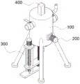
FIG. 1 is a schematic perspective view of a chemical wastewater treatment apparatus provided by the present invention;
FIG. 2 is a sectional view of a chemical wastewater treatment apparatus of FIG. 1;
FIG. 3 is a schematic structural view of a chemical wastewater treatment device in FIG. 2 when a valve plate is in a vertical state;
in the figure: 100-treatment cylinder, 110-cylinder, 111-cavity, 112-sewage outlet, 113-water inlet, 114-water outlet, 115-feed inlet, 120-valve plate, 121-treatment cavity, 130-first valve, 140-second valve, 150-third valve, 200-first rotary driving part, 300-scraping mechanism, 310-scraping plate, 320-driving mechanism, 321-first screw rod, 322-second rotary driving part, 330-mounting frame, 340-lifting plate, 350-lifting mechanism, 351-second screw rod, 352-third rotary driving part, 400-filtering mechanism, 410-filtering piece, 411-filtering hole and 420-telescopic driving part.
Detailed Description
In order to make the objects, technical solutions and advantages of the present invention more clearly understood, the present invention will be further described in detail with reference to the accompanying drawings and embodiments. It should be understood that the specific embodiments described herein are for purposes of illustration only and are not intended to limit the invention.
The utility model provides a chemical wastewater treatment device, the structure of which is shown in fig. 1 and fig. 2, comprising a treatment barrel 100, a first rotary driving member 200 and a scraping mechanism 300, wherein the treatment barrel 100 comprises a barrel body 110, a valve plate 120 and a first valve 130, the barrel body 110 is provided with a cavity 111, the bottom of the barrel body 110 is provided with a sewage outlet 112 communicated with the cavity 111, the valve plate 120 is horizontally arranged in the cavity 111 and is used for forming a closed treatment cavity 121 above the valve plate 120, the barrel body 110 is provided with a water inlet 113 and a water outlet 114 communicated with the treatment cavity 121, and the first valve 130 is arranged at the water outlet 114; the output end of the first rotary driving element 200 is fixedly connected with the valve plate 120, and is used for driving the valve plate 120 to rotate, so that the valve plate 120 is changed from a horizontal state to a vertical state, and when the valve plate 120 is in the vertical state, the treatment cavity 121 is communicated with the sewage discharge outlet 112; the scraping mechanism 300 includes a scraper 310 and a driving mechanism 320, and the driving mechanism 320 is connected to the scraper 310 and is used for driving the scraper 310 to move up and down, so that the scraper 310 scrapes off floc deposits on the surface of the valve plate 120.
When the device is used, the first rotary driving element 200 is operated to enable the first rotary driving element 200 to drive the valve plate 120 to rotate so as to enable the valve plate 120 to be in a horizontal state, so that the closed treatment cavity 121 is formed above the valve plate 120, wastewater is introduced into the treatment cavity 121 through the water inlet 113, chemical reaction substances such as flocculant are added into the treatment cavity 121, after a period of time, the chemical reaction substances such as flocculant react with organic substances in the wastewater to form flocs which are deposited on the valve plate 120, the first valve 130 is opened to enable the treated water to be discharged along the water outlet 114 and to be subjected to subsequent three-stage treatment, the first rotary driving element 200 is operated to enable the first rotary driving element 200 to drive the valve plate 120 to rotate so as to enable the valve plate 120 to be changed from a horizontal state to a vertical state, in the process, a part of the flocs fall off from the surface of the valve plate 120 and are discharged outside the cavity 111 along the water outlet 112, and the driving mechanism 320 is operated to drive the scraper 310 to move up and down, so that the effect of scraping the sludge discharge on the valve plate 120 is improved.
As a preferred embodiment, referring to fig. 2, the cavity 111 is a cylindrical structure, the drain outlet 112 is a cylindrical structure, and the diameter of the drain outlet 112 is equal to the diameter of the cavity 111, so that the valve plate 120 disposed in the cavity 111 can be in a sealed connection with the cavity wall of the cavity 111 when in a horizontal state, thereby forming the treatment cavity 121 above the valve plate 120.
As a preferred embodiment, referring to fig. 1 and fig. 2, the chemical wastewater treatment apparatus further includes a filtering mechanism 400, wherein the filtering mechanism 400 is used for filtering the flocs settled in the treatment chamber 121, so as to prevent a part of the flocs from being discharged from the drainage port 114 together with the wastewater after the flocculation treatment when the wastewater is discharged along the drainage port 114.
As a preferred embodiment, referring to fig. 2, the filtering mechanism 400 includes a filtering element 410 and a telescopic driving element 420, the filtering element 410 is disposed in the processing chamber 121 and is in sliding sealing connection with a chamber wall of the processing chamber 121, a plurality of filtering holes 411 are formed in the filtering element 410 for allowing only water molecules to pass through, the telescopic driving element 420 is fixed on the top of the barrel 110, an output end of the telescopic driving element 420 extends into the processing chamber 121 and is connected to the filtering element 410 for driving the filtering element 410 to move up and down, and when wastewater is introduced into the processing chamber 121 through the water inlet 113, the filtering element 410 is located above the water inlet 113, and when wastewater after flocculation treatment is discharged from the water outlet 114, the telescopic driving element 420 is operated to drive the filtering element 410 to move down to below the water outlet 114, so that floc can be effectively prevented from being discharged from the water outlet 114 together with the wastewater.
As a preferred embodiment, referring to fig. 2 and fig. 3, the water inlet 113 and the water outlet 114 are both disposed on the side wall of the cylinder 110, and the water outlet 114 is disposed below the water inlet 113, when the valve plate 120 is in a horizontal state, a distance between the surface of the valve plate 120 and the water outlet 114 is greater than a thickness of the filter element 410, so that the filter element 410 can move below the water outlet 114 and can filter flocs, the side wall of the valve plate 120 is in an arc-shaped structure, and a sealing ring is disposed on the side wall of the valve plate 120, and the sealing ring is made of a rubber material, so that the sealing effect between the valve plate 120 and the cavity wall of the cavity 111 can be further improved.
As a preferred embodiment, referring to fig. 2 and 3, a feed port 115 communicating with the processing chamber 121 is further formed on a side wall of the cylinder 110, and the feed port 115 has a bent pipe structure such that an opening of the feed port is upward to facilitate feeding of chemical reaction substances such as a flocculant and the like into the processing chamber 121 through the feed port 115.
As a preferred embodiment, referring to fig. 2 and 3, the treatment canister 100 further includes a second valve 140 and a third valve 150, the second valve 140 is disposed at the water inlet 113 for controlling the wastewater, and the third valve 150 is disposed at the feeding port 115 for controlling the addition of chemicals such as flocculant.
As a preferred embodiment, please refer to fig. 2 and fig. 3, the scraping mechanism 300 further includes a mounting frame 330, a lifting plate 340 and a lifting mechanism 350, the lifting plate 340 is disposed below the sewage outlet 112 and is slidably mounted on the mounting frame 330, the lifting mechanism 350 is connected to the lifting plate 340 for driving the lifting plate 340 to move up and down, and as the driving mechanism 320 is connected to the lifting plate 340, the lifting plate 340 can move up and down to drive the driving mechanism 320 and the scraper 310 to move up and down, so that the scraper 310 can extend into the cavity 111 from the sewage outlet 112 to avoid the driving mechanism 320 and the scraper 310 from interfering with the rotation of the valve plate 120.
As a preferred embodiment, please refer to fig. 2 and fig. 3, the driving mechanism 320 includes a first screw rod 321 and a second rotary driving member 322, a lower end of the first screw rod 321 is rotatably installed on the lifting plate 340, the scraper 310 is provided with a first screw hole, and is sleeved on the first screw rod 321 through the corresponding first screw hole, the second rotary driving member 322 is fixed on the lifting plate 340, an output end of the second rotary driving member 322 is fixedly connected with a lower end of the first screw rod 321 for driving the first screw rod 321 to rotate, two ends of the scraper 310 are arc structures for slidably abutting against the side wall of the cavity 111, and the second rotary driving member 322 is operated to drive the first screw rod 321 to rotate, so as to drive the scraper 310 to move up and down, so that the scraper 310 can scrape flocs attached to the surface of the valve plate 120.
As a preferred embodiment, referring to fig. 2 and 3, the lifting mechanism 350 includes a second screw rod 351 and a third rotary driving element 352, two ends of the second screw rod 351 are rotatably mounted on the mounting frame 330, the lifting plate 340 is provided with a second screw hole, and the second screw rod 351 is sleeved with the second screw hole through the corresponding second screw hole, the third rotary driving element 352 is fixed on the mounting frame 330, an output end of the third rotary driving element 352 is fixedly connected with one end of the second screw rod 351 for driving the second screw rod 351 to rotate, by operating the third rotary driving element 352, the third rotary driving element 352 drives the second screw rod 351 to rotate, so that the lifting plate 340 can be driven to move up and down, so that the first screw rod 321 and the scraping plate 310 can extend into the cavity 111 from the sewage discharge outlet 112, thereby scraping off the flocs attached to the valve plate 120, and when the lifting plate 340 descends to the lowest point, the scraping plate 310 can be removed outside the cavity 111, so that the valve plate 120 can not be interfered by the scraping plate 310 when rotating.
For better understanding of the present invention, the following detailed description is made with reference to fig. 1 to 3 for the working principle of the technical solution of the present invention:
in use, by operating the first rotary driving element 200 to make the first rotary driving element 200 drive the valve plate 120 to rotate, so that the valve plate 120 is in a horizontal state, thereby forming a closed processing chamber 121 above the valve plate 120, introducing wastewater into the processing chamber 121 through the water inlet 113, adding chemical reaction substances such as flocculant into the processing chamber 121 through the feed inlet 115, after a period of time, the chemical reaction substances such as flocculant react with organic substances in the wastewater to form flocs which are deposited on the valve plate 120, by operating the telescopic driving element 420, the telescopic driving element 420 drives the filter element 410 to move downwards to a position below the water outlet 114, and then opening the first valve 130 to make the processed water be discharged along the water outlet 114 and perform subsequent three-stage processing, the filter element 410 can effectively avoid the flocs discharged from the water outlet 114 along with the wastewater, and by operating the first rotary driving element 200, the first rotary driving element 200 drives the valve plate 120 to rotate, so that the valve plate 120 is changed from a horizontal state to a state, and the valve plate 120 is changed to a vertical state, so that the flocs are discharged from the water outlet 114 through the second discharge port 112, and the second rotary driving element 321 is driven to rotate by the screw rod 352, so that the second rotary driving element 321 and the discharge plate 120 is moved upwards, the discharge head 321 and the discharge head 321 is driven by the second screw rod 322, so that the second screw rod drives the discharge driving element to rotate, and the discharge rod 320 to rotate, so that the discharge plate 120 to discharge device 320, and the discharge head 320, so that the discharge head 320, the discharge head 320 is driven to discharge head 320 to discharge the screw rod 320 to discharge device 120 to rotate, thereby driving the scraper 310 to move up and down, so that the scraper 310 can scrape off the flocs attached to the surface of the valve plate 120, so that the sludge can be thoroughly discharged, and the pollution discharge effect is improved.
The utility model provides a pair of chemical wastewater treatment device has following beneficial effect:
(1) When the wastewater after flocculation treatment is discharged from the water discharge port 114, the telescopic driving member 420 is operated to drive the filtering member 410 to move downwards to the position below the water discharge port 114, so that flocs can be effectively prevented from being discharged from the water discharge port 114 along with the wastewater;
(2) The third rotary driving element 352 is controlled to drive the second screw rod 351 to rotate, so that the lifting plate 340 can be driven to move downwards, when the lifting plate 340 descends to the lowest point, the scraper 310 moves out of the cavity 111, and the valve plate 120 can not be interfered by the scraper 310 when rotating;
(3) The first rotary driving member 200 drives the valve plate 120 to rotate, so that the valve plate 120 is changed from a horizontal state to a vertical state, in the process, a part of floc falls off from the surface of the valve plate 120 and is discharged to the outside of the cavity 111 along the sewage discharge port 112, and then the second rotary driving member 322 is controlled, so that the second rotary driving member 322 drives the first screw rod 321 to rotate, so that the scraper 310 scrapes the floc attached to the surface of the valve plate 120, sludge can be completely discharged, and the sewage discharge effect is improved.
The above description is intended to illustrate the embodiments of the present invention, and not to limit the scope of the invention. Any other corresponding changes and modifications according to the technical idea of the present invention should be included in the scope of the claims of the present invention.
Claims (10)
1. The utility model provides a chemical industry effluent treatment plant which characterized in that includes:
the treatment device comprises a treatment barrel, a valve plate and a first valve, wherein the treatment barrel comprises a barrel body, the barrel body is provided with a cavity, the bottom of the barrel body is provided with a sewage discharge outlet communicated with the cavity, the valve plate is horizontally arranged in the cavity and is used for forming a closed treatment cavity above the valve plate, the barrel body is provided with a water inlet and a water outlet communicated with the treatment cavity, and the first valve is arranged at the water discharge outlet;
the output end of the first rotary driving piece is fixedly connected with the valve plate and is used for driving the valve plate to rotate so as to enable the valve plate to be changed from a horizontal state to a vertical state, and when the valve plate is in the vertical state, the treatment cavity is communicated with the sewage discharge port;
and the scraping mechanism comprises a scraper and a driving mechanism, the driving mechanism is connected with the scraper and is used for driving the scraper to move up and down so that the scraper can scrape off the floc sediment on the surface of the valve plate.
2. The chemical wastewater treatment device according to claim 1, wherein the cavity is of a columnar structure, the sewage outlet is of a columnar structure, and the diameter of the sewage outlet is equal to that of the cavity.
3. The chemical wastewater treatment device according to claim 2, further comprising a filtering mechanism for filtering floc deposits in the treatment chamber.
4. The chemical wastewater treatment device according to claim 3, wherein the filtering mechanism comprises a filtering member and a telescopic driving member, the filtering member is disposed in the treatment chamber and is in sliding connection with a wall of the treatment chamber, the filtering member is provided with a plurality of filtering holes allowing only water molecules to pass through, the telescopic driving member is fixed on the top of the barrel, and an output end of the telescopic driving member extends into the treatment chamber and is connected with the filtering member for driving the filtering member to move up and down.
5. The chemical wastewater treatment device according to claim 4, wherein the water inlet and the water outlet are both formed in the side wall of the cylinder, the water outlet is formed below the water inlet, and when the valve plate is in a horizontal state, the distance between the surface of the valve plate and the water outlet is larger than the thickness of the filter element.
6. The chemical wastewater treatment device according to claim 5, wherein a feed inlet communicated with the treatment cavity is further formed in the side wall of the cylinder.
7. The chemical wastewater treatment device according to claim 6, wherein the treatment cylinder further comprises a second valve and a third valve, the second valve is arranged at the water inlet, and the third valve is arranged at the material charging port.
8. The chemical wastewater treatment device according to claim 7, wherein the scraping mechanism further comprises a mounting rack, a lifting plate and a lifting mechanism, the lifting plate is arranged below the sewage outlet and is slidably mounted on the mounting rack, and the lifting mechanism is connected with the lifting plate and is used for driving the lifting plate to move up and down.
9. The chemical wastewater treatment device according to claim 8, wherein the driving mechanism comprises a first screw rod and a second rotary driving member, the lower end of the first screw rod is rotatably mounted on the lifting plate, the scraper is provided with a first screw hole, the first screw rod is sleeved with the first screw rod through the corresponding first screw hole, the second rotary driving member is fixed on the lifting plate, and the output end of the second rotary driving member is fixedly connected with the lower end of the first screw rod and is used for driving the first screw rod to rotate.
10. The chemical wastewater treatment device according to claim 9, wherein the lifting mechanism comprises a second screw rod and a third rotary driving member, two ends of the second screw rod are rotatably mounted on the mounting frame, the lifting plate is provided with a second screw hole, the second screw hole is sleeved on the second screw rod through the corresponding second screw hole, the third rotary driving member is fixed on the mounting frame, and an output end of the third rotary driving member is fixedly connected with one end of the second screw rod and used for driving the second screw rod to rotate.
Priority Applications (1)
| Application Number | Priority Date | Filing Date | Title |
|---|---|---|---|
| CN202223202639.7U CN218860501U (en) | 2022-11-30 | 2022-11-30 | Chemical wastewater treatment device |
Applications Claiming Priority (1)
| Application Number | Priority Date | Filing Date | Title |
|---|---|---|---|
| CN202223202639.7U CN218860501U (en) | 2022-11-30 | 2022-11-30 | Chemical wastewater treatment device |
Publications (1)
| Publication Number | Publication Date |
|---|---|
| CN218860501U true CN218860501U (en) | 2023-04-14 |
Family
ID=87355128
Family Applications (1)
| Application Number | Title | Priority Date | Filing Date |
|---|---|---|---|
| CN202223202639.7U Active CN218860501U (en) | 2022-11-30 | 2022-11-30 | Chemical wastewater treatment device |
Country Status (1)
| Country | Link |
|---|---|
| CN (1) | CN218860501U (en) |
-
2022
- 2022-11-30 CN CN202223202639.7U patent/CN218860501U/en active Active
Similar Documents
| Publication | Publication Date | Title |
|---|---|---|
| CN218860501U (en) | Chemical wastewater treatment device | |
| CN113087230A (en) | Multistage electrochemical water treatment equipment with staggered flow guide ports | |
| CN211921108U (en) | Treatment facility of heavy metal contaminated soil drip washing waste water | |
| CN217127194U (en) | Energy-saving water circulation device for smelting and processing | |
| CN111732261A (en) | Wastewater treatment equipment for stainless steel casting production and treatment method thereof | |
| CN116495922A (en) | Recoil type waste liquid treatment device adopting gas aeration | |
| CN217909387U (en) | Polluted groundwater multi-stage treatment device | |
| CN111285497A (en) | Heavy metal settlement separation device for soil | |
| CN216877999U (en) | Sewage treatment deposits device | |
| CN216005425U (en) | Mixed sewage advanced treatment unit | |
| CN112794522B (en) | Organic wastewater pretreatment device and method | |
| CN114835331B (en) | Energy-saving environment-friendly building wastewater treatment device | |
| CN212246549U (en) | Electroplating sewage treatment equipment | |
| CN113716752A (en) | Industrial sewage treatment device and use method thereof | |
| CN212141672U (en) | Industrial sewage treatment equipment capable of self-cleaning solid precipitate | |
| CN220467625U (en) | Environment-friendly filtering device for industrial wastewater | |
| CN215365242U (en) | Industrial wastewater multi-stage treatment device | |
| CN110981040A (en) | Fracturing flow-back fluid treatment device and treatment method | |
| CN215250285U (en) | Moving bed biofilm reactor for sewage treatment | |
| CN218290678U (en) | Sludge water treatment device for tap water plant | |
| CN218435337U (en) | Integrated sewage treatment equipment | |
| CN219279590U (en) | Coking wastewater full mixed flow electric flocculation device | |
| CN219991361U (en) | Building drainage device | |
| CN219489633U (en) | Filter backwash water recovery device | |
| CN212269734U (en) | High-efficient purifier of integral type |
Legal Events
| Date | Code | Title | Description |
|---|---|---|---|
| GR01 | Patent grant | ||
| GR01 | Patent grant |