CN218855664U - Multi-station drilling device for machining limit coupler - Google Patents
Multi-station drilling device for machining limit coupler Download PDFInfo
- Publication number
- CN218855664U CN218855664U CN202222392881.9U CN202222392881U CN218855664U CN 218855664 U CN218855664 U CN 218855664U CN 202222392881 U CN202222392881 U CN 202222392881U CN 218855664 U CN218855664 U CN 218855664U
- Authority
- CN
- China
- Prior art keywords
- workbench
- threaded rod
- assembly
- station
- drilling
- Prior art date
- Legal status (The legal status is an assumption and is not a legal conclusion. Google has not performed a legal analysis and makes no representation as to the accuracy of the status listed.)
- Active
Links
Images


Classifications
-
- Y—GENERAL TAGGING OF NEW TECHNOLOGICAL DEVELOPMENTS; GENERAL TAGGING OF CROSS-SECTIONAL TECHNOLOGIES SPANNING OVER SEVERAL SECTIONS OF THE IPC; TECHNICAL SUBJECTS COVERED BY FORMER USPC CROSS-REFERENCE ART COLLECTIONS [XRACs] AND DIGESTS
- Y02—TECHNOLOGIES OR APPLICATIONS FOR MITIGATION OR ADAPTATION AGAINST CLIMATE CHANGE
- Y02P—CLIMATE CHANGE MITIGATION TECHNOLOGIES IN THE PRODUCTION OR PROCESSING OF GOODS
- Y02P70/00—Climate change mitigation technologies in the production process for final industrial or consumer products
- Y02P70/10—Greenhouse gas [GHG] capture, material saving, heat recovery or other energy efficient measures, e.g. motor control, characterised by manufacturing processes, e.g. for rolling metal or metal working
Landscapes
- Drilling And Boring (AREA)
Abstract
The utility model discloses a multistation drilling equipment is used in processing of limit shaft coupling, this multistation drilling equipment is used in processing of limit shaft coupling aim at solving prior art down can not carry out the multiplex to the limit shaft coupling and handle for processing drilling, use comparatively inconvenient technical problem. The multi-station drilling device comprises a workbench; the inner side of the workbench is provided with a clamping assembly, the upper end of the clamping assembly is provided with a movable clamping plate, the upper end of the workbench is fixedly provided with a fixed clamping plate, the inner side of the workbench is provided with a front-back moving assembly, the upper end of the front-back moving assembly is provided with a supporting plate, and the outer side of the supporting plate is fixedly provided with a left-right moving assembly. The multi-station drilling device for machining the limit coupler only needs to drive the drilling machine to move downwards through the lifting assembly for drilling, and after machining, the back-and-forth moving assembly drives the drilling machine to move to another station for machining, so that multi-station drilling treatment on the limit coupler is achieved.
Description
Technical Field
The utility model belongs to the technical field of the shaft coupling, concretely relates to multistation drilling equipment is used in processing of limit shaft coupling.
Background
The coupler is a mechanical part used for firmly connecting a driving shaft and a driven shaft in different mechanisms to rotate together and transmitting motion and torque, and multiple processes are needed in the production and processing of the limit coupler, wherein a common drilling device for the limit coupler is provided.
At present, the utility model patent of patent number CN202020944657.4 discloses a perforating device is used in shaft coupling processing, the power distribution box comprises a box body, the inside bottom of box is provided with the movable block, the inside one end of movable block is provided with the threaded rod, the movable block is inside to be kept away from the one end of threaded rod is provided with the slide bar, the top of movable block is provided with the fixed station, the inside both sides of fixed station all are provided with the fixed block. The utility model discloses an inside putting the fixed station into with the shaft coupling, the lead screw passes through the interact with fixed station both sides screw hole, realize that the lead screw drives the fixed block and removes in the fixed station is inside, thereby fix the shaft coupling, mutually support through the inside screw hole of threaded rod and movable block, carry on spacingly to the movable block through the slide bar, realize that the effect of movable block removes, remove about the drive shaft coupling, realize the fixed station and take place to rotate with the movable block through the pivot, be convenient for adjust the position of shaft coupling, it is better to have improved perforating device result of use. The drilling device adopts the drilling head to carry out the hole drilling treatment, but the drilling device can not carry out multi-work processing drilling treatment on the limit coupler in the using process, and the use is inconvenient.
Therefore, in order to solve the problem that the conventional multi-station drilling device for machining the limit coupler cannot perform multi-station machining when in use, the device needs to be improved in practicability.
SUMMERY OF THE UTILITY MODEL
(1) Technical problem to be solved
To prior art's not enough, the utility model aims to provide a multistation drilling equipment is used in processing of limit shaft coupling, this multistation drilling equipment is used in processing of limit shaft coupling aims at solving prior art down can not carry out the multiplex to limit shaft coupling and handle for processing drilling, uses comparatively inconvenient technical problem.
(2) Technical scheme
In order to solve the technical problem, the utility model provides a multi-station drilling device for processing a limit coupler, which comprises a workbench; the drilling machine is characterized in that a clamping assembly is arranged on the inner side of the workbench, a movable clamping plate is arranged at the upper end of the clamping assembly, a fixed clamping plate is fixedly mounted at the upper end of the workbench, a front and rear moving assembly is arranged on the inner side of the workbench, a supporting plate is arranged at the upper end of the front and rear moving assembly, a left and right moving assembly is fixedly mounted on the outer side of the supporting plate, a supporting plate is arranged on the outer side of the left and right moving assembly, a lifting assembly is arranged at the bottom end of the supporting plate, and a drilling machine is arranged at the bottom end of the lifting assembly.
When using this technical scheme's multistation drilling equipment is used in limit shaft coupling processing, arrange the upper end of workstation in with the limit shaft coupling, it removes to drive movable clamp plate through the centre gripping subassembly, carry out the centre gripping through movable clamp plate and solid fixed splint to the limit shaft coupling, it removes to the station processing to drive the backup pad through the back-and-forth movement subassembly, it removes to suitable position to drive the drilling machine through removing the subassembly about, it drills to drive the drilling machine lapse through lifting unit, the back-and-forth movement subassembly drives the drilling machine and removes to another station and process after the processing, thereby the multistation drilling treatment to the limit shaft coupling has been realized.
Preferably, the inside of centre gripping subassembly is including first motor, first motor set up in the outside of workstation, the output shaft fixed mounting of first motor has first threaded rod, first threaded rod with the workstation rotates to be connected, starts first motor and drives first threaded rod and rotate, carries out drive processing to first threaded rod.
Furthermore, the inside of centre gripping subassembly is including the screw ring, the screw ring set up in the outside of first threaded rod, the screw ring with first threaded rod lead screw is connected, is connected through the lead screw of first threaded rod and screw ring and drives movable clamp plate and remove.
Still further, the inside of centre gripping subassembly includes the spout, the spout is seted up in the upper end of workstation, the upper end of screw ring is provided with the slider, the upper end of slider with the bottom interconnect of movable splint, the slider with spout sliding connection, the back-and-forth movement subassembly, remove the movable splint and remove the same with centre gripping subassembly structure, remove spacing processing through the sliding connection of spout and slider.
Preferably, the inside of lifting unit is including the second motor, the second motor set up in the upper end of layer board, the output shaft fixed mounting of second motor has the second threaded rod, starts the second motor and drives the rotation of second threaded rod, carries out drive processing to the second threaded rod.
Furthermore, the inside of lifting unit is including a screw thread section of thick bamboo, a screw thread section of thick bamboo set up in the outside of second threaded rod, the bottom of a screw thread section of thick bamboo with the upper end interconnect of drilling machine, the second threaded rod with a screw thread section of thick bamboo lead screw is connected, is connected with the lead screw of a screw thread section of thick bamboo through the second threaded rod and drives the drilling machine and move down and bore.
Still further, the inside of lifting unit includes the gag lever post, gag lever post fixed mounting be in the bottom of layer board, the upper end of drilling machine is provided with a spacing section of thick bamboo, the gag lever post with a spacing section of thick bamboo sliding connection removes spacing processing to the drilling machine through the sliding connection of gag lever post and a spacing section of thick bamboo.
(3) Advantageous effects
Compared with the prior art, the beneficial effects of the utility model reside in that: the utility model discloses a multistation drilling equipment for processing of limit shaft coupling utilizes the upper end of arranging limit shaft coupling in workstation, it rotates to start first motor and drive first threaded rod, it removes to drive movable clamp plate to be connected through the lead screw of first threaded rod and screw ring, sliding connection through spout and slider removes spacing processing to movable clamp plate, carry out the centre gripping through movable clamp plate and solid fixed clamp plate to limit shaft coupling, it removes to the station processing to drive the backup pad through back-and-forth movement subassembly, it removes to suitable position to drive the drilling machine through removing the subassembly about through, it rotates to start the second motor and drive the second threaded rod, it drives the drilling machine and moves down and bore to move through the lead screw connection of second threaded rod and screw thread section of thick bamboo, sliding connection through gag lever post and spacing section of thick bamboo removes spacing processing, back-and-forth movement subassembly drives the drilling machine and removes to another station and process after the processing, thereby the multistation drilling processing to limit shaft coupling has been realized.
Drawings
Fig. 1 is a schematic three-dimensional structure of an embodiment of the present invention;
FIG. 2 is a schematic diagram of an embodiment of the present invention;
FIG. 3 is a schematic structural view of a cross-section of an embodiment of the present invention;
fig. 4 is a schematic view of a partial three-dimensional structure according to an embodiment of the present invention.
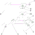
The labels in the figures are: 1. a work table; 2. a clamping assembly; 3. a movable splint; 4. fixing the clamping plate; 5. a forward and backward movement assembly; 6. a support plate; 7. a left-right moving component; 8. a support plate; 9. a lifting assembly; 10. a drilling machine; 11. a first motor; 12. a first threaded rod; 13. a threaded ring; 14. a chute; 15. a slider; 16. a second motor; 17. a second threaded rod; 18. a threaded barrel; 19. a limiting rod; 20. a limiting cylinder.
Detailed Description
Example 1
The embodiment is a multi-station drilling device for processing a limit coupler, the three-dimensional structure of the multi-station drilling device is shown in figure 1, the unfolding structure of the multi-station drilling device is shown in figure 2, and the multi-station drilling device comprises a workbench 1; the inboard of workstation 1 is provided with centre gripping subassembly 2, the upper end of centre gripping subassembly 2 is provided with movable clamp plate 3, the upper end fixed mounting of workstation 1 has solid fixed splint 4, the inboard of workstation 1 is provided with back-and-forth movement subassembly 5, the upper end of back-and-forth movement subassembly 5 is provided with backup pad 6, control subassembly 7 about the outside fixed mounting of backup pad 6, the outside of controlling subassembly 7 is provided with layer board 8, the bottom of layer board 8 is provided with lifting unit 9, lifting unit 9's bottom is provided with drilling machine 10.
For the present embodiment, the shape and structure of the worktable 1 are set according to practical application situations, for example, the worktable 1 may have a rectangular structure, an arc structure, a polygonal structure, and the like.
Wherein, the inside of centre gripping subassembly 2 is including first motor 11, first motor 11 sets up in the outside of workstation 1, the output shaft fixed mounting of first motor 11 has first threaded rod 12, first threaded rod 12 rotates with workstation 1 to be connected, start first motor 11 and drive first threaded rod 12 and rotate, drive first threaded rod 12 and handle, the inside of centre gripping subassembly 2 is including threaded ring 13, threaded ring 13 sets up in the outside of first threaded rod 12, threaded ring 13 is connected with first threaded rod 12 lead screw, it moves movable splint 3 to be connected the drive through the lead screw of first threaded rod 12 with threaded ring 13.
The embodiment is a multi-station drilling device for processing a limit coupler, a schematic sectional structure diagram of the multi-station drilling device is shown in fig. 3, a schematic partial three-dimensional structure diagram of the multi-station drilling device is shown in fig. 4, a sliding groove 14 is formed in a clamping component 2, the sliding groove 14 is formed in the upper end of a workbench 1, a sliding block 15 is arranged at the upper end of a threaded ring 13, the upper end of the sliding block 15 is connected with the bottom end of a movable clamping plate 3, the sliding block 15 is connected with the sliding groove 14 in a sliding mode, a front-back moving component 5, a left-right moving component 7 is identical to the clamping component 2 in structure, the movable clamping plate 3 is subjected to moving limiting treatment through the sliding connection of the sliding groove 14 and the sliding block 15, a second motor 16 is arranged in an inner part of a lifting component 9, the second motor 16 is arranged at the upper end of a supporting plate 8, a second threaded rod 17 is fixedly installed on an output shaft of the second motor 16, and the second motor 16 is started to drive the second threaded rod 17 to rotate.
Meanwhile, the inside of the lifting assembly 9 comprises a thread cylinder 18, the thread cylinder 18 is arranged on the outer side of the second threaded rod 17, the bottom end of the thread cylinder 18 is connected with the upper end of the drilling machine 10, the second threaded rod 17 is connected with a thread cylinder 18 through a screw rod, the drilling machine 10 is driven to move downwards to drill through connection of the second threaded rod 17 and the thread cylinder 18, the inside of the lifting assembly 9 comprises a limiting rod 19, the limiting rod 19 is fixedly installed at the bottom end of the supporting plate 8, the upper end of the drilling machine 10 is provided with a limiting cylinder 20, the limiting rod 19 is connected with the limiting cylinder 20 in a sliding mode, and the drilling machine 10 is driven to move in a limiting mode through sliding connection of the limiting rod 19 and the limiting cylinder 20.
When the multi-station drilling device for machining the limit coupler is used, the limit coupler is arranged at the upper end of the workbench 1, the first motor 11 is started to drive the first threaded rod 12 to rotate, the movable clamp plate 3 is driven to move through connection of the first threaded rod 12 and a threaded ring 13, the movable clamp plate 3 is moved to be limited through sliding connection of the sliding groove 14 and the sliding block 15, the limit coupler is clamped through the movable clamp plate 3 and the fixed clamp plate 4, the supporting plate 6 is driven to move to a station through the front-back moving assembly 5, the drilling machine 10 is driven to move to a proper position through the left-right moving assembly 7, the second motor 16 is started to drive the second threaded rod 17 to rotate, the drilling machine 10 is driven to move downwards through connection of the second threaded rod 17 and a threaded cylinder 18 to drill, the drilling machine 10 is moved to be limited through sliding connection of the limiting rod 19 and the limiting cylinder 20, the front-back moving assembly 5 drives the drilling machine 10 to move to another station to machine after machining, and therefore multi-station drilling treatment on the limit coupler is achieved.
Claims (7)
1. A multi-station drilling device for processing a limit coupler comprises a workbench; the automatic drilling machine is characterized in that a clamping assembly is arranged on the inner side of the workbench, a movable clamping plate is arranged at the upper end of the clamping assembly, a fixed clamping plate is fixedly mounted at the upper end of the workbench, a front-and-back moving assembly is arranged on the inner side of the workbench, a supporting plate is arranged at the upper end of the front-and-back moving assembly, a left-and-right moving assembly is fixedly mounted on the outer side of the supporting plate, a supporting plate is arranged on the outer side of the left-and-right moving assembly, a lifting assembly is arranged at the bottom end of the supporting plate, and a drilling machine is arranged at the bottom end of the lifting assembly.
2. The multi-station drilling device for machining the limit coupler according to claim 1, wherein a first motor is arranged inside the clamping assembly and arranged outside the workbench, a first threaded rod is fixedly mounted on an output shaft of the first motor, and the first threaded rod is rotatably connected with the workbench.
3. The multi-station drilling device for machining the limit coupler according to claim 2, wherein a threaded ring is arranged on the outer side of the first threaded rod and is connected with the first threaded rod through a screw rod.
4. The multi-station drilling device for machining the limit coupler according to claim 3, wherein a sliding groove is formed in the clamping assembly, the sliding groove is formed in the upper end of the workbench, a sliding block is arranged at the upper end of the threaded ring, the upper end of the sliding block is connected with the bottom end of the movable clamping plate, the sliding block is connected with the sliding groove in a sliding mode, and the front-back moving assembly, the left-right moving assembly and the clamping assembly are identical in structure.
5. The multi-station drilling device for machining the limit coupler according to claim 1, wherein a second motor is arranged inside the lifting assembly and is arranged at the upper end of the supporting plate, and a second threaded rod is fixedly mounted on an output shaft of the second motor.
6. The multi-station drilling device for machining the limit coupler according to claim 5, wherein the lifting assembly comprises a threaded cylinder which is arranged on the outer side of the second threaded rod, the bottom end of the threaded cylinder is connected with the upper end of the drilling machine, and the second threaded rod is connected with the threaded cylinder.
7. The multi-station drilling device for machining the limit coupler according to claim 6, wherein a limiting rod is arranged inside the lifting assembly, the limiting rod is fixedly installed at the bottom end of the supporting plate, a limiting barrel is arranged at the upper end of the drilling machine, and the limiting rod is connected with the limiting barrel in a sliding mode.
Priority Applications (1)
| Application Number | Priority Date | Filing Date | Title |
|---|---|---|---|
| CN202222392881.9U CN218855664U (en) | 2022-09-08 | 2022-09-08 | Multi-station drilling device for machining limit coupler |
Applications Claiming Priority (1)
| Application Number | Priority Date | Filing Date | Title |
|---|---|---|---|
| CN202222392881.9U CN218855664U (en) | 2022-09-08 | 2022-09-08 | Multi-station drilling device for machining limit coupler |
Publications (1)
| Publication Number | Publication Date |
|---|---|
| CN218855664U true CN218855664U (en) | 2023-04-14 |
Family
ID=87374884
Family Applications (1)
| Application Number | Title | Priority Date | Filing Date |
|---|---|---|---|
| CN202222392881.9U Active CN218855664U (en) | 2022-09-08 | 2022-09-08 | Multi-station drilling device for machining limit coupler |
Country Status (1)
| Country | Link |
|---|---|
| CN (1) | CN218855664U (en) |
-
2022
- 2022-09-08 CN CN202222392881.9U patent/CN218855664U/en active Active
Similar Documents
| Publication | Publication Date | Title |
|---|---|---|
| CN210997602U (en) | Clamping mechanism on drilling machine | |
| CN212885235U (en) | Drilling machine capable of achieving multidirectional punching | |
| CN218855664U (en) | Multi-station drilling device for machining limit coupler | |
| CN219882267U (en) | High-strength E-type bolt machining clamp capable of avoiding offset | |
| CN210208743U (en) | Machining equipment for machine-building | |
| CN113828821B (en) | Drilling machine for machining | |
| CN213889130U (en) | Surface drilling device for sheet metal working | |
| CN215317107U (en) | Milling machine workpiece pressing device | |
| CN213889159U (en) | Vertical machining center frock clamp | |
| CN211539540U (en) | High-precision radial drilling machine feeding mechanism | |
| CN210817530U (en) | Rapid fixing radial drilling machine | |
| CN112222481B (en) | Bench drilling machine convenient to operation is used | |
| CN220178236U (en) | Drilling machine with rotating function | |
| CN218050502U (en) | Special equipment for automatically milling straight slot on rotor | |
| CN221246826U (en) | Gear blank forging device | |
| CN218051275U (en) | Universal support bilateral drilling and cutting integrated machine | |
| CN219464807U (en) | Table machine tool for positioning countersink in inner cavity | |
| CN220839123U (en) | Multi-cutter efficient boring machine | |
| CN213997921U (en) | Drilling equipment is used in hardware fitting processing | |
| CN220445809U (en) | Adjustable stamping die end face milling jig | |
| CN217701209U (en) | FDS battery package flowing drilling riveting equipment | |
| CN219704281U (en) | Work piece hydraulic pressure centre gripping positioning mechanism | |
| CN220240737U (en) | Workpiece positioning fixture | |
| CN219598193U (en) | Alloy drill thread groove grooving device | |
| CN219582464U (en) | Big water grinder work piece fixed station is used in production of mould chassis |
Legal Events
| Date | Code | Title | Description |
|---|---|---|---|
| GR01 | Patent grant | ||
| GR01 | Patent grant |