CN218853706U - Sludge discharge device for sewage treatment - Google Patents
Sludge discharge device for sewage treatment Download PDFInfo
- Publication number
- CN218853706U CN218853706U CN202320097736.XU CN202320097736U CN218853706U CN 218853706 U CN218853706 U CN 218853706U CN 202320097736 U CN202320097736 U CN 202320097736U CN 218853706 U CN218853706 U CN 218853706U
- Authority
- CN
- China
- Prior art keywords
- sewage
- sewage treatment
- filter screen
- silt
- filter
- Prior art date
- Legal status (The legal status is an assumption and is not a legal conclusion. Google has not performed a legal analysis and makes no representation as to the accuracy of the status listed.)
- Active
Links
Images


Classifications
-
- Y—GENERAL TAGGING OF NEW TECHNOLOGICAL DEVELOPMENTS; GENERAL TAGGING OF CROSS-SECTIONAL TECHNOLOGIES SPANNING OVER SEVERAL SECTIONS OF THE IPC; TECHNICAL SUBJECTS COVERED BY FORMER USPC CROSS-REFERENCE ART COLLECTIONS [XRACs] AND DIGESTS
- Y02—TECHNOLOGIES OR APPLICATIONS FOR MITIGATION OR ADAPTATION AGAINST CLIMATE CHANGE
- Y02W—CLIMATE CHANGE MITIGATION TECHNOLOGIES RELATED TO WASTEWATER TREATMENT OR WASTE MANAGEMENT
- Y02W10/00—Technologies for wastewater treatment
- Y02W10/10—Biological treatment of water, waste water, or sewage
Landscapes
- Treatment Of Sludge (AREA)
Abstract
The utility model discloses a sewage treatment arranges mud device belongs to sewage treatment technical field, including the sewage treatment pond, the embedding is provided with reservoir and silt collecting vat respectively bottom the sewage treatment pond, and inside the being provided with of sewage treatment pond can accelerate the inside impurity pretreatment mechanism that subsides of sewage, and inside the being provided with of reservoir can carry out filtration treatment's row mud mechanism to silt. The utility model discloses a silt cartridge filter can filter in advance the silt in the sewage, through preliminary treatment mechanism, through to adding the flocculating agent in the sewage, can make its flocculating constituent of formation with the impurity fast degradation in the sewage for impurity settling velocity, and then improved sewage treatment efficiency, sewage treatment effect is better, through arranging mud mechanism, filter screen A intercepts the flocculating constituent in the sewage and filters, filter screen B carries out secondary filter to sewage, filters the impurity of less granule.
Description
Technical Field
The utility model belongs to the technical field of sewage treatment, specifically a sewage treatment arranges mud device.
Background
Sewage treatment is the process of purifying sewage, contains impurity such as more mud in the sewage, needs to discharge the mud of accumulational, reserves sufficient storage space for sewage, and mud gathers can block up filtration moreover, for guaranteeing sewage filtration efficiency, provides a sewage treatment row mud device.
The patent number 202221072846.2 discloses a sewage treatment sludge discharge device which comprises a settling frame, a supporting plate, a guide rod, a lower sliding plate, an elastic piece, a first positioning shaft and the like; deposit the frame lower part and install four backup pads, have, discharge sewage in the frame, make the silt in the sewage deposit, the staff passes through the handrail and will slide down the board and move down afterwards, make sewage discharge back, the staff rotates the limiting plate to the inboard, make the stopping plate rotate downwards, after silt has been discharged, and then reach sewage and the effect that silt separately handled, sewage discharge back, the staff starts the cylinder, the telescopic link of cylinder drives connecting plate and catch bar and moves forward, and then discharge silt, thereby save artifical rotation limiting plate, compression spring has certain flexible function, can be faster carry out the advantage that resets with the lower slide.
But through research, the following results are found: the device does not have the structure of accelerating impurity settling velocity in the sewage, needs to stew and deposit the longer time, has reduced the treatment effeciency, and the partial suspended solid in the sewage can't realize depositing through static moreover, and the sewage treatment effect is not good enough, and in addition, the device arranges the mud in-process, needs the staff to rotate the limiting plate, and the mud work can't be arranged automatically, has increased staff's intensity of labour, consequently provides a novel device and solves this problem.
SUMMERY OF THE UTILITY MODEL
The utility model aims to provide a: in order to solve the problems, the sewage treatment sludge discharge device is provided.
The utility model adopts the technical scheme as follows: a sewage treatment sludge discharge device comprises a sewage treatment tank, wherein a liquid storage tank and a sludge collecting tank are embedded into the bottom of the sewage treatment tank respectively;
a pretreatment mechanism capable of accelerating the sedimentation of impurities in the sewage is arranged in the sewage treatment tank, and a sludge discharge mechanism capable of filtering sludge is arranged in the liquid storage tank;
the pretreatment mechanism comprises a pretreatment tank, a stirring rod, a motor, a liquid tank and a metering pump;
the inside one side fixed mounting of sewage treatment pond has the preliminary treatment groove, preliminary treatment inslot portion rotates through the motor and is connected with the puddler, and the puddler is outside to encircle to be provided with the stirring rake, the inside one side fixed mounting of sewage treatment pond has the cistern, the measuring pump is installed in cistern outlet department, and measuring pump and preliminary treatment groove pipe connection, the inside fixed mounting of sewage treatment pond has the connection shell, connect the inside silt cartridge filter that rotates through hollow turntable of shell, and the silt cartridge filter is close to preliminary treatment groove side surface and is provided with the sieve mesh, and outside sewage pipes exports to rotate through hollow turntable and silt cartridge filter entry and be connected, and connects the shell bottom and be provided with the outlet, and the outlet extends to preliminary treatment inslot portion, and connects the shell afterbody and be provided with the mud drain, connect the inside top of shell and correspond a fixed mounting of silt cartridge filter surface sieve mesh and have clean brush, and the puddler passes through chain and be connected with the transmission of silt cartridge filter, and outside all be provided with the sprocket with the chain meshing of silt cartridge filter, the silt filter diameter difference is 30cm, preliminary treatment groove exit is installed the slush pump, and just the drain outlet extends to the reservoir.
Wherein, arrange mud mechanism and include filter screen A, filter screen B, servo electric jar, brush board and baffle, inside fixed mounting side by side of reservoir has filter screen A and filter screen B, the inside one side embedding of reservoir is provided with servo electric jar, the terminal fixed mounting of servo electric jar has the brush board, and servo electric jar and brush board quantity are two, and two brush board brush hairs contact with filter screen A and filter screen B respectively, and be provided with the opening between reservoir and the silt collecting vat, and opening quantity is two, is close to filter screen A and filter screen B respectively, reservoir opposite side opening part rotates through the pivot and is connected with the baffle, and the baffle installs the sealing rubber strip with opening contact area, and the baffle passes through spring and reservoir elastic connection, filter screen A filtration pore diameter is 0.15mm, filter screen B filtration pore is 0.125mm, the water pump is installed in reservoir exit, the dredge pump is installed in silt exit.
To sum up, owing to adopted above-mentioned technical scheme, the beneficial effects of the utility model are that:
1. the utility model discloses in, can carry out prefiltration to the silt in the sewage through the silt cartridge filter, through preliminary treatment mechanism, through to adding the flocculating agent in the sewage, can make it form the flocculating constituent with the impurity fast degradation in the sewage for impurity settling velocity, and then improved sewage treatment efficiency, the sewage treatment effect is better.
2. The utility model discloses in, through row's mud mechanism, filter screen A intercepts the flocculating constituent in with the sewage and filters, filter screen B carries out secondary filter to sewage, the impurity with less granule filters, servo electric jar is reciprocal flexible, it sweeps from filter screen A and filter screen B top to promote the brush board, promote the flocculating constituent of filter screen A and filter screen B top to the silt collecting vat inside, the brush hair of brush board bottom dredges filter screen A and filter screen B filtration pore, avoid blockking up, the filtration efficiency has been guaranteed.
Drawings
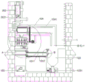
FIG. 1 is a schematic diagram of the overall side section structure of the present invention;
fig. 2 is an enlarged schematic diagram of a structure at a in fig. 1 of the present invention;
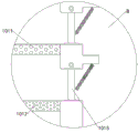
fig. 3 is a schematic diagram of an enlarged structure at B of fig. 1 in the present invention;
fig. 4 is a schematic sketch of the local three-dimensional structure of the middle connecting shell and the sludge filter cartridge of the present invention.
The labels in the figure are: 1. a sewage treatment tank; 101. a liquid storage tank; 1011. a filter screen A; 1012. a filter screen B; 1013. a servo electric cylinder; 1014. brushing the board; 1015. a baffle plate; 102. a water pump; 103. a sludge collecting tank; 1031. a sewage pump; 104. a connecting shell; 1041. a sludge filter cartridge; 1042. a cleaning brush; 2. a pretreatment tank; 201. a stirring rod; 2011. a motor; 202. a liquid bath; 2021. a metering pump; 203. and (5) slurry pumps.
Detailed Description
The technical solutions in the embodiments of the present invention will be described clearly and completely with reference to the accompanying drawings in the embodiments of the present invention, and it is obvious that the described embodiments are only some embodiments of the present invention, not all embodiments. Based on the embodiments in the present invention, all other embodiments obtained by a person skilled in the art without creative work belong to the protection scope of the present invention.
The utility model discloses in:
referring to fig. 1-4, a sewage treatment sludge discharge device comprises a sewage treatment tank 1, wherein a liquid storage tank 101 and a sludge collecting tank 103 are respectively embedded into the bottom of the sewage treatment tank 1;
a pretreatment mechanism capable of accelerating the sedimentation of impurities in the sewage is arranged in the sewage treatment tank 1, and a sludge discharge mechanism capable of filtering sludge is arranged in the liquid storage tank 101;
referring to fig. 1 and 4, further, the pretreatment mechanism includes a pretreatment tank 2, a stirring rod 201, a motor 2011, a fluid bath 202 and a metering pump 2021, one side inside the sewage treatment tank 1 is fixedly provided with the pretreatment tank 2, the inside of the pretreatment tank 2 is rotatably connected with the stirring rod 201 through the motor 2011, the outside of the stirring rod 201 is surrounded by a stirring paddle, one side inside the sewage treatment tank 1 is fixedly provided with the fluid bath 202, an outlet of the fluid bath 202 is provided with the metering pump 2021, the metering pump 2021 is in pipeline connection with the pretreatment tank 2, the inside of the sewage treatment tank 1 is fixedly provided with a connecting shell 104, the inside of the connecting shell 104 is rotatably connected with a sludge filtering cylinder 1041 through a hollow turntable, and the surface of the sludge filtering cylinder 1041, which is close to one side of the pretreatment tank 2, is provided with a sieve mesh, an outlet of an external sewage discharge pipeline is rotatably connected with an inlet of the sludge filter cylinder 1041 through a hollow rotary table, a water outlet is formed in the bottom of the connecting shell 104 and extends to the inside of the pretreatment tank 2, a sludge discharge port is formed in the tail of the connecting shell 104, a cleaning brush 1042 is fixedly mounted at the position, corresponding to a surface sieve pore of the sludge filter cylinder 1041, above the inside of the connecting shell 104, the stirring rod 201 is in transmission connection with the sludge filter cylinder 1041 through a chain, chain wheels meshed with the chain are respectively nested outside the sludge filter cylinder 1041 and outside the stirring rod 201, the diameter difference of two ends of the sludge filter cylinder 1041 is 30cm, a mud pump 203 is mounted at an outlet of the pretreatment tank 2, a sewage discharge pipe is connected at an outlet of the mud pump 203, and the outlet of the sewage discharge pipe extends to the upper part of the liquid storage tank 101;
the external sewage flows into the inside of the sludge filter cylinder 1041 through a pipeline, then the motor 2011 drives the stirring rod 201 to rotate at a high speed, the stirring rod 201 drives the sludge filter cylinder 1041 to rotate, the sewage generates centrifugal force inside the sludge filter cylinder 1041 and is thrown out of a sieve hole on the surface of the sludge filter cylinder 1041 to the inside of the connecting shell 104, and flows into the inside of the pretreatment tank 2 along a water outlet at the bottom of the connecting shell 104, the sludge is intercepted and retained inside the sludge filter cylinder 1041 by the sieve hole, along with the rotation of the sludge filter cylinder 1041, the sludge is thrown out of an outlet at the tail of the sludge filter cylinder 1041 and is discharged from a sludge discharge port at the tail of the connecting shell 104, the rotating sludge filter cylinder 1041 continuously passes through the cleaning brush 1042, the cleaning brush 1042 dredges the sieve hole on the surface of the sludge filter cylinder 1041, the blockage of the sludge filter cylinder is avoided, the filtering efficiency is influenced, the flocculating agent inside the pretreatment tank 2 is guided into the metering pump 1, the sewage and the flocculating agent inside the sludge pump 201 and the stirring rod 201 and the stirring paddle are used for uniformly mixing the sewage, the flocculating agent is quickly degraded by the flocculating agent 203 in the sewage and is guided into the flocculating reservoir 101.
Referring to fig. 1, 2 and 3, further, the sludge discharge mechanism includes a filter screen a1011, a filter screen B1012, a servo electric cylinder 1013, a brush plate 1014 and a baffle 1015, the filter screen a1011 and the filter screen B1012 are fixedly installed in parallel inside the liquid storage tank 101, the servo electric cylinder 1013 is embedded into one side inside the liquid storage tank 101, the brush plate 1014 is fixedly installed at the tail end of the servo electric cylinder 1013, the number of the servo electric cylinder 1013 and the brush plate 1014 is two, bristles of the two brush plates 1014 are respectively in contact with the filter screen a1011 and the filter screen B1012, an opening is formed between the liquid storage tank 101 and the sludge collection tank 103, the number of the openings is two and is respectively close to the filter screen a and the filter screen B1012, the opening at the other side of the liquid storage tank 101 is rotatably connected with a baffle 1015 through a rotating shaft, a sealing rubber strip is installed in a contact area of the baffle 1015 and the opening, the baffle 1015 is elastically connected with the liquid storage tank 101 through a spring, the diameter of a filter hole of the filter screen a 0.15mm, a filter hole of the filter screen B1012 is 0.125mm, a water pump 102 is installed at an outlet of the liquid storage tank 101, and a sludge collection tank 103 is installed with a sewage pump 1031;
sewage flows to reservoir 101 bottom after filter through filter screen A1011 and filter screen B1012 and stores, filter screen A1011 intercepts the flocculating constituent in the sewage and filters, filter screen B1012 carries out secondary filter to sewage, filter the impurity of less granule, servo electric cylinder 1013 is flexible reciprocal, promote brush board 1014 to sweep from filter screen A1011 and filter screen B1012 top, promote the mud of filter screen A1011 and filter screen B1012 top to baffle 1015 department, servo electric cylinder 1013 continues the extension, it rotates to promote baffle 1015, spill the opening, release the flocculating constituent and drop to inside silt collecting vat 103 from the opening part, later servo electric cylinder 1013 shrink resets, baffle 1015 resets under the effect of spring elastic force and shelters from the opening and seals, so reciprocal, the brush hair of 1012 brush board 1014 bottom dredges filter screen A1011 and filter screen B filtration pore, avoid blockking up, filtering efficiency has been guaranteed, later water pump 102 exports the clear sewage that will pass through the filtration and utilizes, dredge pump 1031 then discharges the mud inside silt 103.
Referring to fig. 1 and 2, further, the servo electric cylinder 1013, the water pump 102, the sewage pump 1031, the motor 2011, the metering pump 2021 and the slurry pump 203 are electrically connected to an external power source through a control panel.
The working principle is as follows: firstly, external sewage flows into the inside of the sludge filter cartridge 1041 through a pipeline, then the motor 2011 drives the stirring rod 201 to rotate at a high speed, the stirring rod 201 drives the sludge filter cartridge 1041 to rotate, the sewage generates centrifugal force inside the sludge filter cartridge 1041 and is thrown out of a sieve hole on the surface of the sludge filter cartridge 1041 to the inside of the connecting shell 104, and flows into the inside of the pretreatment tank 2 along a water outlet at the bottom of the connecting shell 104, while the sludge is intercepted and retained inside the sludge filter cartridge 1041 by the sieve hole, along with the rotation of the sludge filter cartridge 1041, the sludge is thrown out from an outlet at the tail part of the sludge filter cartridge 1041 and is discharged into the inside of the sludge collecting tank 103 from a sludge outlet at the tail part of the connecting shell 104 due to different diameters of two ends of the sludge filter cartridge 1041, the rotating sludge filter cartridge 1041 continuously passes through the cleaning brush 1042, the cleaning brush 1042 dredges the sieve hole on the surface of the sludge filter cartridge 1041, and avoids the blockage thereof from influencing the filtering efficiency, the metering pump 2021 guides the flocculating agent in the liquid tank 202 into the pretreatment tank 2, the sewage and the flocculating agent are uniformly mixed by the rotating stirring rod 201 and the stirring paddle, the flocculating agent quickly degrades impurities in the sewage to form floccules, the sewage and the floccules mixture in the pretreatment tank 2 are guided into the liquid storage tank 101 by the slurry pump 203, the sewage flows to the bottom of the liquid storage tank 101 for storage after being filtered by the filter screen A1011 and the filter screen B1012, the floccules in the sewage are intercepted and filtered by the filter screen A1011, the sewage is secondarily filtered by the filter screen B1012, smaller-particle impurities are filtered, the servo electric cylinder 1013 is stretched and retracted back and forth to push the brush plate 1014 to sweep over the filter screen A1011 and the filter screen B1012, the floccules over the filter screen A1011 and the filter screen B1012 are pushed to the baffle 1015, the servo electric cylinder 1013 is continuously stretched to push the baffle 1015 to rotate, spill the opening, release mud from the opening part and drop to inside silt collecting vat 103, later servo electric jar 1013 shrink resets, baffle 1015 resets under the effect of spring elastic force and shelters from the opening and seals, so reciprocal, the brush hair of brush board 1014 bottom dredges filter screen A1011 and filter screen B1012 filtration pore, avoid blockking up, filtration efficiency has been guaranteed, water pump 102 will utilize through filterable limpid sewage derivation at last, dredge pump 1031 then discharges the inside mud of silt collecting vat 103.
The above description is only exemplary of the present invention and should not be taken as limiting the scope of the present invention, as any modifications, equivalents, improvements and the like made within the spirit and principles of the present invention are intended to be included within the scope of the present invention.
Claims (7)
1. The utility model provides a sewage treatment arranges mud device, includes sewage treatment pond (1), its characterized in that: a liquid storage tank (101) and a sludge collecting tank (103) are respectively embedded into the bottom of the sewage treatment tank (1);
a pretreatment mechanism capable of accelerating the sedimentation of impurities in the sewage is arranged in the sewage treatment tank (1), and a sludge discharge mechanism capable of filtering sludge is arranged in the liquid storage tank (101);
the pretreatment mechanism comprises a pretreatment tank (2), a stirring rod (201), a motor (2011), a liquid tank (202) and a metering pump (2021);
inside one side fixed mounting in sewage treatment pond (1) has preliminary treatment groove (2), preliminary treatment groove (2) are inside to rotate through motor (2011) and are connected with puddler (201), and puddler (201) is outside to be provided with the stirring rake around, inside one side fixed mounting in sewage treatment pond (1) has cistern (202), metering pump (2021) is installed in cistern (202) exit, and metering pump (2021) and preliminary treatment groove (2) pipe connection.
2. The sewage treatment sludge discharge device according to claim 1, wherein: inside fixed mounting in sewage treatment pond (1) has connection shell (104), it is connected with silt cartridge filter (1041) to connect shell (104) inside to rotate through hollow rotary table, and silt cartridge filter (1041) is close to pretreatment tank (2) side surface and is provided with the sieve mesh, and outside sewage pipes exports and passes through hollow rotary table and is connected with silt cartridge filter (1041) entry rotation, and connects shell (104) bottom and be provided with the outlet, and the outlet extends to inside pretreatment tank (2), and connects shell (104) afterbody and be provided with the mud discharging mouth, connect shell (104) inside top and silt cartridge filter (1041) surface sieve mesh department of correspondence fixed mounting have cleaning brush (1042), and puddler (201) are connected through chain and silt cartridge filter (1041) transmission, and silt cartridge filter (1041) outside and puddler (201) outside all nested be provided with the sprocket with chain meshing, silt cartridge filter (1041) both ends diameter difference is 30cm.
3. The sewage treatment sludge discharge device according to claim 1, wherein: mud pump (203) are installed to preliminary treatment groove (2) exit, and mud pump (203) exit is connected with the blow off pipe, and the blow off pipe export extends to reservoir (101) top.
4. The sewage treatment sludge discharge device according to claim 1, wherein: the mud discharging mechanism comprises a filter screen A (1011), a filter screen B (1012), a servo electric cylinder (1013), a brush plate (1014) and a baffle plate (1015);
the inside fixed mounting side by side of reservoir (101) has filter screen A (1011) and filter screen B (1012), the inside one side embedding of reservoir (101) is provided with servo electric jar (1013), servo electric jar (1013) end fixed mounting has brush board (1014), and servo electric jar (1013) and brush board (1014) quantity are two, and two brush board (1014) brush hairs respectively with filter screen A (1011) and filter screen B (1012) contact, and be provided with the opening between reservoir (101) and silt collecting vat (103), and the opening quantity is two, be close to filter screen A (1011) and filter screen B (1012) respectively, reservoir (101) opposite side opening part is connected with baffle (1015) through the pivot rotation, and baffle (1015) and opening contact area install the sealing rubber strip, and baffle (1015) pass through spring and reservoir (101) elastic connection.
5. The sewage treatment sludge discharge apparatus according to claim 4, wherein: the diameter of the filter hole of the filter screen A (1011) is 0.15mm, and the diameter of the filter hole of the filter screen B (1012) is 0.125mm.
6. The sewage treatment sludge discharge device according to claim 1, wherein: and a water pump (102) is arranged at the outlet of the liquid storage tank (101).
7. The sewage treatment sludge discharge device according to claim 1, wherein: and a sewage pump (1031) is arranged at the outlet of the sludge collecting tank (103).
Priority Applications (1)
| Application Number | Priority Date | Filing Date | Title |
|---|---|---|---|
| CN202320097736.XU CN218853706U (en) | 2023-02-01 | 2023-02-01 | Sludge discharge device for sewage treatment |
Applications Claiming Priority (1)
| Application Number | Priority Date | Filing Date | Title |
|---|---|---|---|
| CN202320097736.XU CN218853706U (en) | 2023-02-01 | 2023-02-01 | Sludge discharge device for sewage treatment |
Publications (1)
| Publication Number | Publication Date |
|---|---|
| CN218853706U true CN218853706U (en) | 2023-04-14 |
Family
ID=87367184
Family Applications (1)
| Application Number | Title | Priority Date | Filing Date |
|---|---|---|---|
| CN202320097736.XU Active CN218853706U (en) | 2023-02-01 | 2023-02-01 | Sludge discharge device for sewage treatment |
Country Status (1)
| Country | Link |
|---|---|
| CN (1) | CN218853706U (en) |
-
2023
- 2023-02-01 CN CN202320097736.XU patent/CN218853706U/en active Active
Similar Documents
| Publication | Publication Date | Title |
|---|---|---|
| CN209530279U (en) | A kind of sewage treatment fibre turntable formula filter device | |
| CN218810700U (en) | Environment-friendly engineering sewage precipitation and purification device | |
| CN114308860B (en) | Water washing device for producing phosphogypsum and application method thereof | |
| CN218853706U (en) | Sludge discharge device for sewage treatment | |
| CN213823697U (en) | Lobster is bred and uses water filtration processing apparatus | |
| CN211025255U (en) | High-efficient sedimentation tank | |
| CN112125446A (en) | Tap water purification sedimentation tank and purification method thereof | |
| CN219058804U (en) | Belt filter | |
| CN111701333A (en) | Sewage filtering equipment capable of avoiding flocculation adhesion | |
| CN110755913A (en) | Nano ceramic sewage filter | |
| CN110981019A (en) | Community sewage discharge device based on sewage treatment | |
| CN115845467A (en) | Sewage filtering device | |
| CN214192971U (en) | Mud sedimentation tank for treating polluted bottom mud of river and lake | |
| CN208762373U (en) | A kind of efficient domestic sludge solidification equipment | |
| CN212119174U (en) | Waste water treatment purifier | |
| CN113856283A (en) | River course integration sewage treatment device suitable for deposit mud | |
| CN219502074U (en) | Purifying tank for town sewage treatment | |
| CN217297522U (en) | Municipal administration plumbing sewage treatment device | |
| CN219764585U (en) | Environment-friendly sewage precipitation and filtration device | |
| CN220070888U (en) | Liquid epoxy filter equipment | |
| CN215756786U (en) | Effectual sedimentation tank for sewage treatment of clearance | |
| CN214328790U (en) | Water diversion structure for water conservancy and hydropower engineering | |
| CN211635507U (en) | Nano ceramic sewage filter | |
| CN213823785U (en) | Integrated urban and rural sewage regeneration, purification and filtration device | |
| CN219964044U (en) | Rain sewage filters sedimentation tank |
Legal Events
| Date | Code | Title | Description |
|---|---|---|---|
| GR01 | Patent grant | ||
| GR01 | Patent grant |