CN218809575U - Rewinding machine for recycling aluminum alloy waste wire - Google Patents
Rewinding machine for recycling aluminum alloy waste wire Download PDFInfo
- Publication number
- CN218809575U CN218809575U CN202223469816.8U CN202223469816U CN218809575U CN 218809575 U CN218809575 U CN 218809575U CN 202223469816 U CN202223469816 U CN 202223469816U CN 218809575 U CN218809575 U CN 218809575U
- Authority
- CN
- China
- Prior art keywords
- aluminum alloy
- lead screw
- fixedly connected
- supports
- alloy waste
- Prior art date
- Legal status (The legal status is an assumption and is not a legal conclusion. Google has not performed a legal analysis and makes no representation as to the accuracy of the status listed.)
- Active
Links
Images
Classifications
-
- Y—GENERAL TAGGING OF NEW TECHNOLOGICAL DEVELOPMENTS; GENERAL TAGGING OF CROSS-SECTIONAL TECHNOLOGIES SPANNING OVER SEVERAL SECTIONS OF THE IPC; TECHNICAL SUBJECTS COVERED BY FORMER USPC CROSS-REFERENCE ART COLLECTIONS [XRACs] AND DIGESTS
- Y02—TECHNOLOGIES OR APPLICATIONS FOR MITIGATION OR ADAPTATION AGAINST CLIMATE CHANGE
- Y02W—CLIMATE CHANGE MITIGATION TECHNOLOGIES RELATED TO WASTEWATER TREATMENT OR WASTE MANAGEMENT
- Y02W30/00—Technologies for solid waste management
- Y02W30/50—Reuse, recycling or recovery technologies
- Y02W30/82—Recycling of waste of electrical or electronic equipment [WEEE]
Abstract
The utility model discloses an aluminum alloy waste wire retrieves and uses rewinder belongs to rewinder technical field, comprising a base plate, two first supports of bottom plate top one side fixedly connected with, and rotate through main pivot and bearing between two supports and be connected with the rolling roller bearing, two second supports of bottom plate one side fixedly connected with, and rotate between two second supports and be connected with the wiring subassembly, wiring subassembly top fixed connection tightens the subassembly. The utility model discloses in, through setting up the subassembly that tightens, the dwang passes through the worm and drives the worm wheel rotation, and the worm wheel drives two first lead screw seats through two adjustment lead screws and is close to each other, and two first lead screw seats drive two laminating rollers and be close to each other and closely laminate with the aluminum alloy waste wire for the aluminum alloy waste wire is tight state of tightening between coiling roller bearing and laminating roller, appears flabby form easily when can avoiding the aluminum alloy waste wire winding, thereby improves the coiling effect.
Description
Technical Field
The utility model belongs to the technical field of the rewinder, especially, relate to an aluminum alloy waste wire retrieves and uses rewinder.
Background
The aluminum alloy wire winding machine has the advantages that a lot of waste wires can be generated in the processing process of the aluminum alloy wire, in order to better recover the waste wires, the waste wires are often recovered by using a rewinding machine, the rewinding machine is used for rewinding copper wires, aluminum wires, iron wires, plastic aluminum wires and plastic copper wires on a disc, is an auxiliary machine for outgoing wires of an electric wire unit and stranding of a stranding machine unit, and is widely used for winding various metal wires.
The invention discloses a steel wire rewinding machine in the field of partial rewinding machines in the prior art, wherein the invention with the application number of CN202122419557.7 discloses a steel wire rewinding machine which comprises an operation table, wherein an unwinding mechanism is fixedly arranged on the upper surface of the operation table, an unwinding wheel is fixedly sleeved on the surface of the unwinding mechanism, a winding mechanism is fixedly arranged on the upper surface of the operation table, a winding wheel is fixedly sleeved on the surface of the winding mechanism, and side plates are symmetrically and fixedly arranged on the upper surface of the operation table, so that the height limiting adjustment of steel wires on the surfaces of the unwinding wheels with different sizes before rewinding operation is completed, and the subsequent limiting work of the steel wires is conveniently realized.
However, in the actual process of winding the aluminum alloy waste wire, the aluminum alloy waste wire is easy to loose when being wound, so that the aluminum alloy waste wire on the rewinder is easy to loose when being wound, and the aluminum alloy waste wire on the winding roller is not attached to the winding roller.
SUMMERY OF THE UTILITY MODEL
The utility model aims to provide a: in order to solve the problem that the aluminum alloy waste wire is not attached to a winding roller in the prior art, the rewinder for recycling the aluminum alloy waste wire is provided.
In order to achieve the above purpose, the utility model adopts the following technical scheme:
a rewinding machine for recovering aluminum alloy waste wires comprises a bottom plate, wherein one side of the top of the bottom plate is fixedly connected with two first supports, a winding roller is rotatably connected between the two supports through a main rotating shaft and a bearing, one side of the bottom plate is fixedly connected with two second supports, a wiring assembly is rotatably connected between the two second supports, and the top of the wiring assembly is fixedly connected with a tightening assembly;
the wiring assembly comprises a reciprocating screw rod, the reciprocating screw rod is rotatably connected between two second supports, the outer surface of the reciprocating screw rod is in threaded connection with a first screw rod seat, a sliding rod is fixedly connected between the two second supports, the sliding rod is located below the reciprocating screw rod, a sliding sleeve is embedded in the first screw rod seat, and the sliding rod is slidably connected in the sliding sleeve.
The technical effect of adopting the further scheme is as follows: through setting up the wiring subassembly, reciprocal lead screw cooperation rolling roller bearing synchronous rotation, reciprocal lead screw drives aluminum alloy waste wire reciprocating motion, makes aluminum alloy waste wire can be orderly convoluteing on the rolling roller bearing.
As a further description of the above technical solution:
reciprocating screw one end extends to second support one side and fixedly connected with from the driving wheel through the pivot, and main pivot one end extends to first support one side and fixedly connected with action wheel, the action wheel with from the driving connection between the driving wheel be connected with the drive belt.
The technical effect of adopting the further scheme is as follows: through the arrangement of the driving wheel and the driven wheel, the rolling roller is synchronously linked with the reciprocating screw rod, the power source is reduced, and the energy consumption is saved.
As a further description of the above technical solution:
the tightening assembly comprises a connecting block, the bottom of the connecting block is fixedly connected with the top of the first screw seat, a groove is formed in the top of the connecting block, two adjusting screws are rotatably connected in the groove, the outer surface of each adjusting screw is in threaded connection with the second screw seat, and the top of the second screw seat is rotatably connected with the laminating roller through a rotating shaft and a bearing.
The technical effect of adopting the further scheme is as follows: through setting up the subassembly that tightens, two first lead screw seats drive two laminating rollers and be close to each other and closely laminate with the aluminum alloy waste line for the aluminum alloy waste line is the state of tightening between coiling roller bearing and laminating roller.
As a further description of the above technical solution:
two fixedly connected with worm wheel between the adjustment lead screw seat, the meshing of worm wheel bottom has the worm, the inside joint of worm has the dwang, dwang one end extends to outside and the fixedly connected with knob of recess.
The technical effect of adopting the further scheme is as follows: through setting up the knob, make things convenient for the user of service to rotate the dwang, the dwang passes through the worm and drives the worm wheel rotation.
As a further description of the above technical solution:
two the adjustment lead screw is symmetrical along worm wheel central point and distributes, and two adjustment lead screw thread opposite direction.
The technical effect of adopting the further scheme is as follows: the thread directions of the two adjusting screw rods are opposite, so that when the two adjusting screw rods rotate in the same direction, the two laminating rollers can be relatively close to each other, and the aluminum alloy waste wire is clamped in a limiting manner.
As a further description of the above technical solution:
one end of the main rotating shaft extends to the outer side of the first support and is fixedly connected with a rotating disc, and an anti-skid pad is arranged on the outer side of the rotating disc.
The technical effect of adopting the further scheme is as follows: through setting up the rolling disc, the rolling disc can make things convenient for user of service more laborsaving rotation main pivot.
To sum up, owing to adopted above-mentioned technical scheme, the beneficial effects of the utility model are that:
1. the utility model discloses in, through setting up the subassembly that tightens, the staff passes through the knob and drives the dwang rotation, the dwang passes through the worm and drives the worm wheel rotation, the worm wheel drives two first lead screw seats through two adjustment lead screws and is close to each other, two first lead screw seats drive two laminating rollers and be close to each other and closely laminate with the aluminum alloy waste line for the aluminum alloy waste line is the state of tightening between coiling roller bearing and laminating roller, appear flabby form easily when can avoiding the winding of aluminum alloy waste line, thereby improve the coiling effect.
2. The utility model discloses in, through setting up the wiring subassembly, the action wheel passes through the drive belt and drives from the driving wheel rotation, drive reciprocal lead screw rotation from the driving wheel, reciprocal lead screw drives second lead screw seat and is reciprocating motion, second lead screw seat drives the subassembly of tightening and drives the aluminum alloy waste wire at slide bar transverse direction reciprocating motion, make the position that the aluminum alloy waste wire can constantly adjust the coiling at the in-process of rolling, make the coiling that the aluminum alloy waste wire can be orderly on the rolling roller bearing, realized arranging in order to the aluminum alloy waste wire.
Drawings
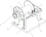
Fig. 1 is a schematic perspective view of the present invention;
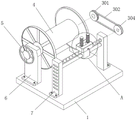
FIG. 2 is a schematic view of the three-dimensional splitting structure of the present invention;
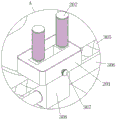
FIG. 3 is an enlarged schematic view of part A of the present invention;
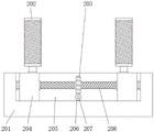
fig. 4 is a schematic side view of the tightening assembly of the present invention.
Illustration of the drawings: 1. a base plate; 2. a tightening assembly; 201. connecting blocks; 202. a laminating roller; 203. a worm gear; 204. a first lead screw base; 205. a groove; 206. a worm; 207. rotating the rod; 208. adjusting a screw rod; 209. a knob; 3. a wiring assembly; 301. a driving wheel; 302. a transmission belt; 303. a driven wheel; 304. a reciprocating screw; 305. a slide bar; 306. a second lead screw base; 4. rolling a roller; 5. rotating the disc; 6. a first bracket; 7. a second bracket; 8. a main rotating shaft.
Detailed Description
The technical solutions in the embodiments of the present invention will be described clearly and completely with reference to the accompanying drawings in the embodiments of the present invention, and it is obvious that the described embodiments are only some embodiments of the present invention, not all embodiments. Based on the embodiments of the present invention, all other embodiments obtained by a person skilled in the art without making creative efforts belong to the protection scope of the present invention.
Referring to fig. 1-4, the present invention provides a technical solution: the utility model provides an aluminum alloy waste wire retrieves and uses rewinder, comprising a base plate 1, two first supports 6 of 1 top one side fixedly connected with of bottom plate, and rotate through main pivot 8 and bearing between two supports and be connected with rolling roller bearing 4, two second supports 7 of 1 one side fixedly connected with of bottom plate, and rotate between two second supports 7 and be connected with wiring assembly 3, the subassembly 2 is tightened to 3 top fixed connection of wiring assembly, 8 one end of main pivot extends to the 6 outsides of first support and fixedly connected with rolling disc 5, the 5 outsides of rolling disc are provided with the slipmat.
The wiring assembly 3 comprises a reciprocating screw 304, the reciprocating screw 304 is rotatably connected between two second supports 7, a first screw seat 204 is connected to the outer surface of the reciprocating screw 304 in a threaded manner, a slide rod 305 is fixedly connected between the two second supports 7, the slide rod 305 is positioned below the reciprocating screw 304, a slide sleeve is embedded in the first screw seat 204, the slide rod 305 is slidably connected in the slide sleeve, one end of the reciprocating screw 304 extends to one side of each second support 7 through a rotating shaft and is fixedly connected with a driven wheel 303, one end of a main rotating shaft 8 extends to one side of each first support 6 and is fixedly connected with a driving wheel 301, a transmission belt 302 is connected between the driving wheel 301 and the driven wheel 303, the driving wheel 301 drives the driven wheel 303 to rotate through the transmission belt 302 by virtue of the arrangement of the wiring assembly 3, the driven wheel 303 drives the reciprocating screw 304 to rotate, the reciprocating screw 304 drives the second screw seat 306 to reciprocate, the second screw seat 306 drives the tightening assembly 2 to drive the aluminum alloy waste wire to reciprocate in the transverse direction of the slide rod 305, the winding position of the aluminum alloy waste wire can be continuously adjusted in the winding process, and the aluminum alloy waste wire can be orderly arranged.
The tightening assembly 2 comprises a connecting block 201, the bottom of the connecting block 201 is fixedly connected with the top of a first lead screw seat 204, a groove 205 is formed in the top of the connecting block 201, two adjusting lead screws 208 are connected in the groove 205 in a rotating mode, the two adjusting lead screws 208 are symmetrically distributed along the central position of a worm wheel 203, the thread directions of the two adjusting lead screws 208 are opposite, a second lead screw seat 306 is connected to the outer surface of each adjusting lead screw 208 in a threaded mode, the top of the second lead screw seat 306 is connected with a fitting roller 202 through a rotating shaft and a bearing in a rotating mode, a worm wheel 203 is fixedly connected between the two adjusting lead screw seats 208, a worm 206 is meshed at the bottom of the worm wheel 203, a rotating rod 207 is clamped inside the worm 206, one end of the rotating rod 207 extends to the outside of the groove 205 and is fixedly connected with a knob 209, the tightening assembly 2 is arranged, a worker drives the rotating rod 207 to rotate through the worm wheel 206, the rotating rod 207 drives the worm wheel 203 to rotate through the two adjusting lead screw seats 204, the two first lead screw seats 204 are driven by the two first lead screw seats 204, the two fitting rollers 202 are driven to be close to each other and tightly fit the aluminum alloy waste wire, so that the aluminum alloy waste wire is easily tightened between the rolling shaft and the waste wire and the rolling shaft is easily loosened.
The working principle is as follows: during the use, the staff is convoluteed aluminum alloy waste wire one end in 4 surfaces of rolling roller bearing, later, pass two laminating with aluminum alloy waste wire one side and roll between, the staff rotates knob 209, knob 209 drives dwang 207 and rotates, dwang 207 drives worm 206 and rotates, worm 206 drives worm wheel 203 and rotates, worm wheel 203 drives two adjustment lead screws 208 and rotates, two adjustment lead screws 208 drive two first lead screw seats 204 and are close to each other, two first lead screw seats 204 drive two laminating rollers 202 and are close to each other and closely laminate with the aluminum alloy waste wire.
After the limitation of the aluminum alloy waste wire is completed, the working personnel rotate the rotating disc 5, the rotating disc 5 drives the main rotating shaft 8 to rotate, the main rotating shaft 8 drives the rolling roller 4 to rotate, the rolling roller 4 drives the aluminum alloy waste wire to be wound on the outer surface of the rolling roller 4, in the process, the rolling roller 4 drives the driving wheel 301 to rotate through the main rotating shaft 8, the driving wheel 301 drives the driven wheel 303 to rotate through the transmission belt 302, the driven wheel 303 drives the reciprocating screw 304 to rotate, the reciprocating screw 304 drives the second screw seat 306 to reciprocate, and the second screw seat 306 drives the tightening component 2 to drive the aluminum alloy waste wire to reciprocate in the transverse direction of the sliding rod 305.
The above, only be the concrete implementation of the preferred embodiment of the present invention, but the protection scope of the present invention is not limited thereto, and any person skilled in the art is in the technical scope of the present invention, according to the technical solution of the present invention and the utility model, the concept of which is equivalent to replace or change, should be covered within the protection scope of the present invention.
Claims (6)
1. The utility model provides an aluminum alloy waste wire retrieves uses rewinder, includes bottom plate (1), its characterized in that: two first supports (6) are fixedly connected to one side of the top of the bottom plate (1), a winding roller (4) is rotatably connected between the two supports through a main rotating shaft (8) and a bearing, two second supports (7) are fixedly connected to one side of the bottom plate (1), a wiring assembly (3) is rotatably connected between the two second supports (7), and the top of the wiring assembly (3) is fixedly connected with a tightening assembly (2);
the wiring assembly (3) comprises a reciprocating lead screw (304), the reciprocating lead screw (304) is rotatably connected between two second supports (7), the outer surface of the reciprocating lead screw (304) is in threaded connection with a first lead screw seat (204), a sliding rod (305) is fixedly connected between the two second supports (7), the sliding rod (305) is located below the reciprocating lead screw (304), a sliding sleeve is embedded in the first lead screw seat (204), and the sliding rod (305) is slidably connected in the sliding sleeve.
2. The rewinding machine for recycling aluminum alloy scrap wires according to claim 1, characterized in that: reciprocal lead screw (304) one end extends to second support (7) one side and fixedly connected with from driving wheel (303) through the pivot, and main pivot (8) one end extends to first support (6) one side and fixedly connected with action wheel (301), the transmission is connected with drive belt (302) between action wheel (301) and follow driving wheel (303).
3. The rewinding machine for recycling aluminum alloy scrap wires according to claim 1, characterized in that: the tightening assembly (2) comprises a connecting block (201), the bottom of the connecting block (201) is fixedly connected with the top of a first lead screw seat (204), a groove (205) is formed in the top of the connecting block (201), two adjusting lead screws (208) are connected to the groove (205) in a rotating mode, a second lead screw seat (306) is connected to the outer surface of each adjusting lead screw (208) in a threaded mode, and the top of the second lead screw seat (306) is connected with a laminating roller (202) in a rotating mode through a rotating shaft and a bearing.
4. The rewinding machine for recycling aluminum alloy scrap wires according to claim 3, characterized in that: two fixedly connected with worm wheel (203) between adjustment lead screw (208) seat, worm wheel (203) bottom meshing has worm (206), the inside joint of worm (206) has dwang (207), dwang (207) one end extends to recess (205) outside and fixedly connected with knob (209).
5. The rewinding machine for recycling aluminum alloy scrap wires according to claim 4, characterized in that: the two adjusting screw rods (208) are symmetrically distributed along the center of the worm wheel (203), and the thread directions of the two adjusting screw rods (208) are opposite.
6. The rewinding machine for recycling aluminum alloy scrap wires according to claim 1, characterized in that: one end of the main rotating shaft (8) extends to the outer side of the first support (6) and is fixedly connected with a rotating disc (5), and an anti-skid pad is arranged on the outer side of the rotating disc (5).
Priority Applications (1)
| Application Number | Priority Date | Filing Date | Title |
|---|---|---|---|
| CN202223469816.8U CN218809575U (en) | 2022-12-23 | 2022-12-23 | Rewinding machine for recycling aluminum alloy waste wire |
Applications Claiming Priority (1)
| Application Number | Priority Date | Filing Date | Title |
|---|---|---|---|
| CN202223469816.8U CN218809575U (en) | 2022-12-23 | 2022-12-23 | Rewinding machine for recycling aluminum alloy waste wire |
Publications (1)
| Publication Number | Publication Date |
|---|---|
| CN218809575U true CN218809575U (en) | 2023-04-07 |
Family
ID=87272911
Family Applications (1)
| Application Number | Title | Priority Date | Filing Date |
|---|---|---|---|
| CN202223469816.8U Active CN218809575U (en) | 2022-12-23 | 2022-12-23 | Rewinding machine for recycling aluminum alloy waste wire |
Country Status (1)
| Country | Link |
|---|---|
| CN (1) | CN218809575U (en) |
-
2022
- 2022-12-23 CN CN202223469816.8U patent/CN218809575U/en active Active
Similar Documents
| Publication | Publication Date | Title |
|---|---|---|
| CN107553263A (en) | A kind of sheet metal surface flatness process equipment | |
| CN110712081A (en) | Copper line drawing machine is used in production of mineral substance insulation fireproof cable | |
| CN111975525A (en) | Two-sided grinding device of corrosion resistant plate edge burr | |
| CN218809575U (en) | Rewinding machine for recycling aluminum alloy waste wire | |
| CN213054058U (en) | Square steel sheet edge burnishing and polishing device | |
| CN113955540A (en) | High performance aluminium foil production is with rolling up device | |
| CN211104221U (en) | Novel L DPE composite sheet slitting device | |
| CN211414640U (en) | Steel band trimming machine | |
| CN205167547U (en) | Rubber roller three -roller rubber coating machine | |
| CN219542258U (en) | Special alloy steel pipe making machine | |
| CN216127028U (en) | Burnishing device is used in coil of strip processing | |
| CN216189658U (en) | High performance aluminium foil production is with rolling up device | |
| CN113400159B (en) | Finish machining equipment for manufacturing and forming power accessories of power transmission line | |
| CN211414589U (en) | Copper line drawing machine is used in production of mineral substance insulation fireproof cable | |
| CN210755977U (en) | Gantry type double-arm welding machine | |
| CN204608472U (en) | Base cloth press | |
| CN210147679U (en) | Device convenient to timber is polished | |
| CN207239880U (en) | A kind of sheet metal surface flatness process equipment | |
| CN214213339U (en) | Energy-saving type rolled steel plate surface polishing processing device | |
| CN210703573U (en) | High-precision hydraulic gate type plate shearing machine | |
| CN218925797U (en) | Small sheet metal rolling and bending dual-purpose device | |
| CN211218953U (en) | Diamond wire cutting machine tool | |
| CN220665771U (en) | Cutting structure for panty hose production | |
| CN218507140U (en) | Ultrasonic embossing machine | |
| CN210306524U (en) | Roller carrier pressing device |
Legal Events
| Date | Code | Title | Description |
|---|---|---|---|
| GR01 | Patent grant | ||
| GR01 | Patent grant | ||
| TR01 | Transfer of patent right |
Effective date of registration: 20230905 Address after: 454350 grinding village, five Li Yuan Township, Xiu Wu County, Jiaozuo, Henan Patentee after: Xiuwu Shenghao Aluminum Industry Co.,Ltd. Address before: No. L098, Luocheng Brand, Nanhai District, Foshan City, Guangdong Province, 528,000 Patentee before: Guo Guandi |
|
| TR01 | Transfer of patent right |