CN218791107U - Foot pad device for table and chair - Google Patents
Foot pad device for table and chair Download PDFInfo
- Publication number
- CN218791107U CN218791107U CN202222619996.7U CN202222619996U CN218791107U CN 218791107 U CN218791107 U CN 218791107U CN 202222619996 U CN202222619996 U CN 202222619996U CN 218791107 U CN218791107 U CN 218791107U
- Authority
- CN
- China
- Prior art keywords
- foot pad
- callus
- main part
- fixedly connected
- sole main
- Prior art date
- Legal status (The legal status is an assumption and is not a legal conclusion. Google has not performed a legal analysis and makes no representation as to the accuracy of the status listed.)
- Expired - Fee Related
Links
Images



Landscapes
- Finger-Pressure Massage (AREA)
Abstract
本实用新型公开了一种桌椅的脚垫装置,涉及桌椅脚垫装置技术领域,包括脚垫主体,所述脚垫主体的内部设置有辅助移动机构,所述辅助移动机构包括连接杆,所述连接杆的外表面转动连接有移动轮,所述连接杆的两端均固定连接有连接块,两个所述连接块的外表面均开设有一组限位孔,两个所述连接块相互远离的一侧面均固定连接有六角块,两个所述连接块的外表面均固定连接有相对称的限位板。它能够通过脚垫主体和辅助移动机构之间的配合设置,能够使得人们较为方便的对桌子进行移动,避免了由于桌重量较大而导致的人们在对其进行移动的过程中较为麻烦的情况,进一步的节约了人力,减少了人们的在对桌子进行移动过程中的麻烦。

The utility model discloses a foot pad device for tables and chairs, relates to the technical field of table and chair foot pad devices, and comprises a foot pad main body, an auxiliary moving mechanism is arranged inside the foot pad main body, and the auxiliary moving mechanism includes a connecting rod, The outer surface of the connecting rod is rotatably connected with a moving wheel, the two ends of the connecting rod are fixedly connected with connecting blocks, and the outer surfaces of the two connecting blocks are provided with a group of limiting holes, and the two connecting blocks The side faces away from each other are fixedly connected with hexagonal blocks, and the outer surfaces of the two connecting blocks are fixedly connected with symmetrical limiting plates. It can be set through the cooperation between the main body of the foot pad and the auxiliary moving mechanism, so that people can move the table more conveniently, avoiding the troublesome situation in the process of moving the table due to the heavy weight of the table , which further saves manpower and reduces people's troubles in the process of moving the table.
Description
技术领域technical field
本实用新型涉及桌椅脚垫装置技术领域,具体是一种桌椅的脚垫装置。The utility model relates to the technical field of table and chair foot pad devices, in particular to a table and chair foot pad device.
背景技术Background technique
桌椅是我们日常生活中较常见的一种居家或者办公用品,对于桌子而言,是由桌腿和桌板组成,在我们生活中较常见的桌腿通常为金属材质或者木质材质,如果使用金属材质有可能会对室内的地砖造成划伤,但是当使用木质材质的话可能会由于日常拖地的原因导致地砖上潮湿,从而导致木质的桌腿被腐蚀,为了避免上述两种情况,人们需要使用一种脚垫来对其进行保护。Tables and chairs are a kind of household or office supplies that are more common in our daily life. For a table, it is composed of a table leg and a table board. The table legs that are more common in our life are usually made of metal or wood. If you use Metal materials may cause scratches to the indoor floor tiles, but when using wooden materials, the floor tiles may be damp due to daily mopping, which will cause the wooden table legs to be corroded. In order to avoid the above two situations, people need Use a mat to protect it.
根据专利号为CN107981592B的专利中公开的一种用于户外餐桌椅的脚垫装置,该装置包括滑移设置在储物桶内的加压板,加压板的上表面转动连接有工作杆,储物桶的顶部固定设有盖体,工作杆螺纹贯穿盖体与外部相通;本脚垫装置利用磁泥的柔软性可以较好的填补地面中的各种物体间的间隙,改善桌椅放置的环境,保证桌椅在任何环境下放置平稳性。According to a foot pad device for outdoor dining tables and chairs disclosed in the patent No. CN107981592B, the device includes a pressure plate slidingly arranged in the storage bucket, and the upper surface of the pressure plate is rotatably connected with a working rod , the top of the storage bucket is fixed with a cover, and the thread of the working rod runs through the cover to communicate with the outside; this foot pad device uses the softness of magnetic mud to better fill the gaps between various objects in the ground and improve the table and chairs. The environment in which the tables and chairs are placed ensures the stability of the tables and chairs in any environment.
在人们使用脚垫装置对桌子的桌腿进行保护的时候,首先须将桌子抬起,然后将脚垫装置固定于桌腿的底端,以此防止桌腿直接与室内的地砖或者地面直接接触,由于桌子的重量较大,会使得人们在对其进行移动的过程中较为费力,但是上述装置在使用的过程中,不具备辅助移动的功能,从而导致桌子不能够较为方便的移动,因此需要人们在移动桌子的时候仍然需要耗费较多的人力,不方便人们使用;为此,我们提供了一种桌椅的脚垫装置解决以上问题。When people use the foot pad device to protect the table legs of the table, the table must be lifted first, and then the foot pad device is fixed to the bottom of the table leg, so as to prevent the table leg from directly contacting the indoor floor tiles or the ground , due to the heavy weight of the table, people will be more laborious in the process of moving it, but the above-mentioned device does not have the function of assisting the movement during use, so that the table cannot be moved more conveniently, so it is necessary to People still need to consume more manpower when moving the table, which is inconvenient for people to use; for this reason, we provide a foot pad device for tables and chairs to solve the above problems.
实用新型内容Utility model content
本实用新型的目的就是为了弥补现有技术的不足,提供了一种桌椅的脚垫装置。The purpose of the utility model is to provide a foot pad device for tables and chairs in order to make up for the deficiencies of the prior art.
为实现上述目的,本实用新型提供如下技术方案:一种桌椅的脚垫装置,包括脚垫主体,脚垫主体的材质为较硬的塑胶材质,所述脚垫主体的内部设置有辅助移动机构,所述辅助移动机构包括连接杆,所述连接杆的外表面转动连接有移动轮,移动轮通过连接杆外表面所安装的轴承实现与连接杆的转动连接,所述连接杆的两端均固定连接有连接块,两个所述连接块均延伸至脚垫主体的外部且与脚垫主体滑动连接,两个所述连接块的外表面均开设有一组限位孔,每组限位孔的数量为三个,两个所述连接块相互远离的一侧面均固定连接有六角块,通过设置六角块能够使得人们较为方便的向下滑动连接块,两个所述连接块的外表面均固定连接有相对称的限位板,两个所述连接块的上表面均固定连接有弹簧一,通过设置弹簧一能够起到复位作用,且在弹簧一处于原始状态下,移动轮位于脚垫主体的内部。In order to achieve the above purpose, the utility model provides the following technical solutions: a foot pad device for tables and chairs, including a foot pad main body, the material of the foot pad main body is a relatively hard plastic material, and the interior of the foot pad main body is provided with an auxiliary moving mechanism, the auxiliary moving mechanism includes a connecting rod, the outer surface of the connecting rod is rotatably connected with a moving wheel, and the moving wheel realizes the rotational connection with the connecting rod through the bearing installed on the outer surface of the connecting rod, and the two ends of the connecting rod Both are fixedly connected with connecting blocks, and the two connecting blocks extend to the outside of the main body of the foot pad and are slidably connected with the main body of the foot pad. The outer surfaces of the two connecting blocks are provided with a set of limiting holes, each set of limiting The number of holes is three, and the sides of the two connecting blocks away from each other are fixedly connected with a hexagonal block. By setting the hexagonal block, people can slide the connecting block down more conveniently. The outer surfaces of the two connecting blocks Both are fixedly connected with symmetrical limit plates, and the upper surfaces of the two connecting blocks are fixedly connected with a spring one, which can play a reset role by setting the spring one, and when the spring one is in the original state, the moving wheel is located on the foot. Pad the inside of the main body.
进一步的,所述脚垫主体的内壁固定连接有支撑板,两个所述弹簧一均固定连接于支撑板的底面,通过设置支撑板能够对桌腿起到支撑作用,在安装该装置的时候须保证桌腿的底端与支撑板的上表面相接触。Further, the inner wall of the main body of the foot pad is fixedly connected with a support plate, and one of the two springs is fixedly connected to the bottom surface of the support plate. By setting the support plate, the table legs can be supported. When the device is installed Make sure that the bottom end of the table leg is in contact with the upper surface of the support plate.
进一步的,所述脚垫主体的内壁开设有一组限位槽,所述限位板滑动连接于限位槽的内壁,通过将限位板滑动与限位槽的内壁,能够防止连接块在脚垫主体的内部左右移动。Further, the inner wall of the main body of the foot pad is provided with a set of limiting grooves, the limiting plate is slidably connected to the inner wall of the limiting groove, and by sliding the limiting plate to the inner wall of the limiting groove, the connecting block can be prevented from The inside of the pad body moves left and right.
进一步的,所述脚垫主体的内壁滑动连接有相对称的夹持板,两个所述夹持板相互远离的一侧面均转动连接有螺纹杆,夹持板的两侧壁与脚垫主体的内壁相接触,通过两个夹持板的夹持作用能够实现对桌腿底端的夹持固定。Further, the inner wall of the main body of the foot pad is slidably connected with a symmetrical clamping plate, and the sides of the two clamping plates away from each other are rotatably connected with threaded rods, and the two side walls of the clamping plate are connected to the main body of the foot pad. The inner wall of the table leg is in contact, and the clamping and fixing of the bottom end of the table leg can be realized through the clamping action of the two clamping plates.
进一步的,两个所述螺纹杆均延伸至脚垫主体的外部且与脚垫主体螺纹连接,两个所述螺纹杆相互远离的一端均固定连接有手柄,通过设置手柄能够使得人们较为方便的转动螺纹杆,通过转动螺纹杆能够带动两个夹持板相互靠近,以此来实现对桌腿的夹持固定,便于将该装置安装于桌腿的底端。Further, both of the two threaded rods extend to the outside of the main body of the foot pad and are threadedly connected with the main body of the foot pad. The ends of the two threaded rods that are far away from each other are fixedly connected with handles. Rotating the threaded rod can drive the two clamping plates to approach each other, so as to realize the clamping and fixing of the table leg, and facilitate the installation of the device on the bottom end of the table leg.
进一步的,所述脚垫主体的正面设置有活动板,所述活动板靠近脚垫主体的一侧面固定连接有一组限位杆,所述限位杆与限位孔相适配,通过将限位杆插入限位孔的内部能够实现对连接块的固定,从而使得能够将移动轮从脚垫主体的底部伸出,来实现对桌子的移动。Further, the front of the main body of the foot pad is provided with a movable plate, and a side of the movable plate close to the main body of the foot pad is fixedly connected with a set of limit rods, and the limit rods are adapted to the limit holes. Inserting into the inside of the limiting hole can realize the fixing of the connecting block, so that the moving wheel can be stretched out from the bottom of the foot pad main body to realize the movement of the table.
进一步的,所述活动板靠近脚垫主体的一侧面均固定连接有相对称的滑动杆,两个所述滑动杆均与脚垫主体滑动连接且延伸至脚垫主体的内部,两个所述滑动杆的外表面均固定连接有限位垫,两个所述滑动杆的外表面均套设有弹簧二,两个所述弹簧二均固定连接于脚垫主体的内壁,通过设置限位垫能够防止滑动杆脱离脚垫主体,且通过活动板向外移动能够带动滑动杆向外移动,随着滑动杆的向外移动能够带动限位垫向外移动,此时弹簧二处于压缩状态。Further, one side of the movable plate close to the main body of the foot pad is fixedly connected with a symmetrical sliding rod, and the two sliding rods are slidably connected with the main body of the foot pad and extend to the inside of the main body of the foot pad. The outer surfaces of the sliding rods are all fixedly connected to the limit pads, and the outer surfaces of the two sliding rods are all sleeved with springs two, and the two springs are fixedly connected to the inner wall of the main body of the foot pads. Prevent the sliding bar from breaking away from the main body of the foot pad, and the outward movement of the movable plate can drive the sliding bar to move outward, and the outward movement of the sliding bar can drive the limit pad to move outward. At this time, the second spring is in a compressed state.
与现有技术相比,该桌椅的脚垫装置具备如下有益效果:Compared with the prior art, the foot pad device of the table and chair has the following beneficial effects:
1、本实用新型通过脚垫主体和辅助移动机构之间的配合设置,能够使得人们较为方便的对桌子进行移动,从而有效的避免了由于桌重量较大而导致的人们在对其进行移动的过程中较为麻烦的情况,进一步的节约了人力,并且减少了人们的在对桌子进行移动过程中的麻烦,方便人们使用。1. The utility model enables people to move the table more conveniently through the cooperative arrangement between the main body of the foot pad and the auxiliary moving mechanism, thus effectively avoiding people's trouble of moving the table due to the heavy weight of the table. The more troublesome situation in the process further saves manpower, and reduces people's troubles in the process of moving the table, which is convenient for people to use.
2、本实用新型通过活动板、限位杆、连接块、限位孔和移动轮之间的配合设置,能够使得人们在对桌子进行移动的过程中较为方便的移动轮进行定位,通过将限位杆插入限位孔内,能够实现对连接块的定位,以此来实现对移动轮的定位,能够使得在移动轮的辅助下较为方便的对桌子进行移动。2. The utility model can enable people to locate the moving wheel more conveniently in the process of moving the table through the cooperation between the movable plate, the limit rod, the connecting block, the limit hole and the moving wheel. The position bar is inserted into the position-limiting hole to realize the positioning of the connecting block, thereby realizing the positioning of the moving wheel, and enabling the table to be moved more conveniently with the assistance of the moving wheel.
附图说明Description of drawings
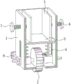
图1为本实用新型的立体结构正视示意图;Fig. 1 is the schematic diagram of the front view of the three-dimensional structure of the utility model;
图2为本实用新型脚垫主体的内部结构示意图;Fig. 2 is a schematic diagram of the internal structure of the utility model foot pad main body;
图3为本实用新型辅助移动机构的立体结构示意图;Fig. 3 is a three-dimensional structural schematic diagram of the auxiliary moving mechanism of the utility model;
图4为本实用新型的部分结构示意图。Fig. 4 is a partial structural diagram of the utility model.
图中:1、脚垫主体;2、辅助移动机构;201、连接杆;202、移动轮;203、连接块;204、限位孔;205、六角块;206、限位板;207、弹簧一;3、支撑板;4、限位槽;5、夹持板;6、螺纹杆;7、手柄;8、活动板;9、限位杆;10、滑动杆;11、限位垫;12、弹簧二。Among the figure: 1, foot pad main body; 2, auxiliary moving mechanism; 201, connecting rod; 202, moving wheel; 203, connecting block; 204, limiting hole; 205, hexagonal block; 206, limiting plate; 207,
具体实施方式Detailed ways
以下结合附图对本实用新型的原理和特征进行描述,所举实例只用于解释本实用新型,并非用于限定本实用新型的范围。The principles and features of the present utility model are described below in conjunction with the accompanying drawings, and the examples given are only used to explain the utility model, and are not used to limit the scope of the utility model.
本实施例提供了一种桌椅的脚垫装置,该装置通过脚垫主体1和辅助移动机构2之间的配合设置,能够使得人们较为方便的对桌子进行移动,从而有效的避免了由于桌重量较大而导致的人们在对其进行移动的过程中较为麻烦的情况,进一步的节约了人力,并且减少了人们的在对桌子进行移动过程中的麻烦,方便人们使用。This embodiment provides a foot pad device for tables and chairs. Through the cooperation between the foot pad
参见图1、图2和图3,一种桌椅的脚垫装置,包括脚垫主体1,脚垫主体1的材质为较硬的塑胶材质,脚垫主体1的内部设置有辅助移动机构2,辅助移动机构2包括连接杆201,连接杆201的外表面转动连接有移动轮202,移动轮202通过连接杆201外表面所安装的轴承实现与连接杆201的转动连接。Referring to Fig. 1, Fig. 2 and Fig. 3, a foot pad device for tables and chairs includes a foot pad
连接杆201的两端均固定连接有连接块203,两个连接块203均延伸至脚垫主体1的外部且与脚垫主体1滑动连接,两个连接块203的外表面均开设有一组限位孔204,每组限位孔204的数量为三个。Both ends of the connecting
两个连接块203相互远离的一侧面均固定连接有六角块205,通过设置六角块205能够使得人们较为方便的向下滑动连接块203,两个连接块203的外表面均固定连接有相对称的限位板206,两个连接块203的上表面均固定连接有弹簧一207,通过设置弹簧一207能够起到复位作用,且在弹簧一207处于原始状态下,移动轮202位于脚垫主体1的内部。The sides of the two connecting
脚垫主体1的内壁固定连接有支撑板3,两个弹簧一207均固定连接于支撑板3的底面,通过设置支撑板3能够对桌腿起到支撑作用,在安装该装置的时候须保证桌腿的底端与支撑板3的上表面相接触。The inner wall of the
参见图1、图2和图4,脚垫主体1的内壁开设有一组限位槽4,限位板206滑动连接于限位槽4的内壁,通过将限位板206滑动与限位槽4的内壁,能够防止连接块203在脚垫主体1的内部左右移动,脚垫主体1的内壁滑动连接有相对称的夹持板5,两个夹持板5相互远离的一侧面均转动连接有螺纹杆6,夹持板5的两侧壁与脚垫主体1的内壁相接触,通过两个夹持板5的夹持作用能够实现对桌腿底端的夹持固定。Referring to Fig. 1, Fig. 2 and Fig. 4, the inner wall of the main body of the
两个螺纹杆6均延伸至脚垫主体1的外部且与脚垫主体1螺纹连接,两个螺纹杆6相互远离的一端均固定连接有手柄7,通过设置手柄7能够使得人们较为方便的转动螺纹杆6,通过转动螺纹杆6能够带动两个夹持板5相互靠近,以此来实现对桌腿的夹持固定,便于将该装置安装于桌腿的底端。Two threaded
脚垫主体1的正面设置有活动板8,活动板8靠近脚垫主体1的一侧面固定连接有一组限位杆9,限位杆9与限位孔204相适配,通过将限位杆9插入限位孔204的内部能够实现对连接块203的固定,从而使得能够将移动轮202从脚垫主体1的底部伸出,来实现对桌子的移动。The front of foot pad
活动板8靠近脚垫主体1的一侧面均固定连接有相对称的滑动杆10,两个滑动杆10均与脚垫主体1滑动连接且延伸至脚垫主体1的内部,两个滑动杆10的外表面均固定连接有限位垫11,两个滑动杆10的外表面均套设有弹簧二12,两个弹簧二12均固定连接于脚垫主体1的内壁,通过设置限位垫11能够防止滑动杆10脱离脚垫主体1,且通过活动板8向外移动能够带动滑动杆10向外移动,随着滑动杆10的向外移动能够带动限位垫11向外移动,此时弹簧二12处于压缩状态。The
工作原理:在该装置使用的过程中,首先将桌子抬起,然后将桌腿的底端插入脚垫主体1内,直至与支撑板3的上表面相接触,然后通过手柄7转动螺纹杆6,直至夹持板5与桌腿的外表面相接触,以此来实现对该装置的安装,当需要对桌子进行移动的过程中,人们首先通过活动板8上的把手向外拉动活动板8,随着活动板8的向外拉动能够带动限位杆9向外滑动,然后人们通过六角块205向下滑动连接块203,随着连接块203的向下滑动能够带动连接杆201的向下滑动,进而带动移动轮202向下滑动,直至能够将限位杆9插入限位孔204内,此时移动轮202漏出脚垫主体1的底面,然后通过移动轮202的辅助作用能够使得人们较为方便的移动桌子,从而有效的避免了由于桌重量较大而导致的人们在对其进行移动的过程中较为麻烦的情况,进一步的节约了人力,并且减少了人们的在对桌子进行移动过程中的麻烦,方便人们使用。Working principle: in the process of using the device, first lift the table, then insert the bottom end of the table leg into the main body of the
以上所述仅为本实用新型的较佳实施例,并不用以限制本实用新型,凡在本实用新型的精神和原则之内,所作的任何修改、等同替换、改进等,均应包含在本实用新型的保护范围之内。The above descriptions are only preferred embodiments of the present utility model, and are not intended to limit the present utility model. Any modifications, equivalent replacements, improvements, etc. made within the spirit and principles of the present utility model shall be included in this utility model. within the scope of protection of utility models.
Claims (7)
Priority Applications (1)
| Application Number | Priority Date | Filing Date | Title |
|---|---|---|---|
| CN202222619996.7U CN218791107U (en) | 2022-10-08 | 2022-10-08 | Foot pad device for table and chair |
Applications Claiming Priority (1)
| Application Number | Priority Date | Filing Date | Title |
|---|---|---|---|
| CN202222619996.7U CN218791107U (en) | 2022-10-08 | 2022-10-08 | Foot pad device for table and chair |
Publications (1)
| Publication Number | Publication Date |
|---|---|
| CN218791107U true CN218791107U (en) | 2023-04-07 |
Family
ID=87271227
Family Applications (1)
| Application Number | Title | Priority Date | Filing Date |
|---|---|---|---|
| CN202222619996.7U Expired - Fee Related CN218791107U (en) | 2022-10-08 | 2022-10-08 | Foot pad device for table and chair |
Country Status (1)
| Country | Link |
|---|---|
| CN (1) | CN218791107U (en) |
-
2022
- 2022-10-08 CN CN202222619996.7U patent/CN218791107U/en not_active Expired - Fee Related
Similar Documents
| Publication | Publication Date | Title |
|---|---|---|
| CN207125543U (en) | Lift environmental protection sofa | |
| CN209448264U (en) | A kind of base used specially of regulated power supply cabinet | |
| CN215776989U (en) | Design drawing show shelf for indoor decoration | |
| CN211572467U (en) | Connecting device is laid to rubber floor | |
| CN220365320U (en) | Engineering construction trowelling device | |
| CN211323584U (en) | Special table of architectural design | |
| CN210865638U (en) | an instrument box | |
| CN216287287U (en) | Model connection structure for architectural design | |
| CN211269539U (en) | Office chair armrest fixing device | |
| CN217852317U (en) | Household folding shoe-wearing stool | |
| CN220247801U (en) | A building construction fence | |
| CN218606331U (en) | Novel elastic tissue box | |
| CN208763831U (en) | A kind of hydraulic hand-pump with foot pedal apparatus | |
| CN211271825U (en) | Bedding support device for ward | |
| CN221229010U (en) | Cabinet handle with stable installation | |
| CN222894876U (en) | A connection base for machining | |
| CN217494026U (en) | A mounting support for fixing the position of a container floor | |
| CN219165880U (en) | Movable steel-wood furniture | |
| CN222622433U (en) | Design showcase | |
| CN221671184U (en) | Height-adjustable desk | |
| CN222787318U (en) | A combined office desk and chair | |
| CN219794556U (en) | Skirting line fixing device | |
| CN224193134U (en) | Multifunctional shoe rack with storage stool | |
| CN220483964U (en) | Equipment case appurtenance loses detection mechanism | |
| CN217365126U (en) | Movable foldable dining chair with round stool |
Legal Events
| Date | Code | Title | Description |
|---|---|---|---|
| GR01 | Patent grant | ||
| GR01 | Patent grant | ||
| CF01 | Termination of patent right due to non-payment of annual fee | ||
| CF01 | Termination of patent right due to non-payment of annual fee |
Granted publication date: 20230407 |