CN218780002U - Heavy object reinforcing structure of assembled partition wall module - Google Patents
Heavy object reinforcing structure of assembled partition wall module Download PDFInfo
- Publication number
- CN218780002U CN218780002U CN202222072042.9U CN202222072042U CN218780002U CN 218780002 U CN218780002 U CN 218780002U CN 202222072042 U CN202222072042 U CN 202222072042U CN 218780002 U CN218780002 U CN 218780002U
- Authority
- CN
- China
- Prior art keywords
- keel
- fossil fragments
- sides
- keels
- vertical
- Prior art date
- Legal status (The legal status is an assumption and is not a legal conclusion. Google has not performed a legal analysis and makes no representation as to the accuracy of the status listed.)
- Active
Links
Images


Classifications
-
- Y—GENERAL TAGGING OF NEW TECHNOLOGICAL DEVELOPMENTS; GENERAL TAGGING OF CROSS-SECTIONAL TECHNOLOGIES SPANNING OVER SEVERAL SECTIONS OF THE IPC; TECHNICAL SUBJECTS COVERED BY FORMER USPC CROSS-REFERENCE ART COLLECTIONS [XRACs] AND DIGESTS
- Y02—TECHNOLOGIES OR APPLICATIONS FOR MITIGATION OR ADAPTATION AGAINST CLIMATE CHANGE
- Y02B—CLIMATE CHANGE MITIGATION TECHNOLOGIES RELATED TO BUILDINGS, e.g. HOUSING, HOUSE APPLIANCES OR RELATED END-USER APPLICATIONS
- Y02B30/00—Energy efficient heating, ventilation or air conditioning [HVAC]
- Y02B30/90—Passive houses; Double facade technology
Landscapes
- Joining Of Building Structures In Genera (AREA)
Abstract
The utility model discloses an assembled partition wall module heavy object reinforced structure, including consolidating fossil fragments, support piece, hanging the dress board, many consolidate the parallel setting of fossil fragments and stand between top layer, bottom, it is a plurality of support piece transversely erects in consolidate between the fossil fragments and form bearing frame with the fossil fragments frame attach of both sides, it is located to hang the dress board bearing frame's front and at least two consolidate the fossil fragments rigid coupling, just hang the rigid coupling position of dress board with support piece's mounted position does not overlap. The utility model discloses set up at the carry position and hang special skeleton to use this skeleton to lay conventional wall module to both sides as the center, provide good hoist and mount basic unit.
Description
Technical Field
The utility model relates to a fitment technical field especially relates to an assembled partition wall module heavy object reinforced structure.
Background
The background wall is a decoration wall widely applied to indoor space, is not only suitable for home decoration of a television background wall, a sofa background wall, a hallway, a bedroom wall and the like in a family living room, but also can be applied to decoration of entertainment places such as hotel restaurants, song halls KTV, night clubs and the like.
With the wide application of background walls, the devices mounted on the background walls are more and more diversified, and when a conventional framework structure is used for carrying out larger and heavier objects and electric appliances, the framework has weak structural stability and insufficient bearing capacity
SUMMERY OF THE UTILITY MODEL
For solving the problem that exists among the prior art, the utility model provides an assembled partition wall module heavy object reinforced structure sets up at the carry position and hangs special skeleton to use this skeleton to lay conventional wall module to both sides as the center, provide good hoist and mount basic unit.
The utility model provides a technical scheme of problem does, provides an assembled partition wall module heavy object reinforced structure, including consolidating fossil fragments, support piece, hanging the dress board, many consolidate the parallel setting of fossil fragments and stand between top layer, bottom, it is a plurality of support piece transversely erects in consolidate between the fossil fragments and form bearing frame with the fossil fragments frame attach of both sides, it is located to hang the dress board bearing frame's front and at least two consolidate the fossil fragments rigid coupling, just hang the rigid coupling position of dress board with support piece's the position of erectting does not overlap.
Furthermore, the keel frame comprises a top keel, a bottom keel, a transverse keel and a vertical keel, wherein the vertical keel is provided with a through hole, so that the transverse keel can be inserted into the vertical keel; the grooves of the top keel and the bottom keel are oppositely arranged, and the upper end and the lower end of the vertical keel are respectively inserted into the grooves of the top keel and the bottom keel.
Furthermore, the top keel comprises a group of L-shaped upper clamping pieces, each upper clamping piece comprises an upper inner clamping piece and an upper outer clamping piece, and the upper inner clamping pieces and the upper outer clamping pieces are fixed on the top layer at intervals in parallel, so that a groove can be formed between the upper inner clamping pieces and the upper outer clamping pieces; the bottom keel comprises a group of L-shaped lower clamping pieces, each lower clamping piece comprises a lower inner clamping piece and a lower outer clamping piece, and the lower inner clamping pieces and the lower outer clamping pieces are fixed on the bottom layer at intervals in parallel, so that a groove can be formed between the lower inner clamping pieces and the lower outer clamping pieces. The top keel is inverted to form a top groove, and the upper ends of the vertical keels are clamped into the top groove; the bottom keel is rightly arranged to form a bottom groove, and the lower ends of the vertical keels are all clamped in the bottom groove. The width of the groove is not less than the width of the vertical keel.
Further, the vertical keel further comprises edge-closing keels located on two sides of the keel frame, and the two grooves of the edge-closing keels are arranged oppositely, so that two ends of the transverse keel are respectively inserted into the grooves of the edge-closing keels on the two sides.
Furthermore, the two ends of the supporting piece are bent downwards to form abutting plates, and the abutting plates at the two ends of the supporting piece are respectively fixedly connected with top plates of the edge-closing keels of the keel frames, which are positioned on the two sides of the bearing frame.
Furthermore, the fixed connection positions of the bearing frame and the hanging plate are provided with cross beams and vertical beams, two cross beams are transversely fixed with the plurality of reinforcing keels, two ends of each vertical beam are respectively fixed with the two cross beams, and two ends of each cross beam are respectively fixed with the keel frames positioned on two sides of the bearing frame; the hanging plate is fixed on the two cross beams.
Furthermore, a through hole is formed in the reinforcing keel, so that the supporting piece can be sequentially inserted into the plurality of reinforcing keels along the through hole.
Further, consolidate the fossil fragments set up in support piece's the place ahead and with the support piece rigid coupling, just consolidate the front surface and the both sides of fossil fragments frame parallel and level.
Furthermore, the supporting piece is located at the top end of the reinforcing keel, the line passing box is arranged on the supporting piece and located in the ceiling layer of the top layer, and therefore the line passing box can be in butt joint communication with the distributing box in the ceiling layer.
Further, the supporting piece is located on the lower portion of the reinforcing keel, a switch box is arranged on the supporting piece, and the switch box is located below the top layer.
Furthermore, a group of L-shaped upper fixing pieces are arranged at the upper end of the reinforcing keel, and the two upper fixing pieces are respectively arranged on two sides of the top end of the reinforcing keel and fixedly connected with the top layer; the lower extreme of consolidating the fossil fragments is provided with the lower firmware of a set of L type, two down the firmware branch is located consolidate the both sides of fossil fragments bottom and with bottom rigid coupling
Furthermore, the apex angle butt of going up the firmware extremely consolidate the butt joint angle of fossil fragments and top layer, go up the horizontal right angle board of firmware with the top layer passes through expansion bolts to be fixed, the vertical right angle board of going up the firmware with it passes through the bolt fastening to consolidate the fossil fragments. Furthermore, the vertical right-angle plates of the two upper fixing pieces on the two sides of the reinforced keel can share one bolt to realize fixed connection. The firmware can be set similarly.
The utility model has the advantages that:
the utility model relates to an assembled partition wall module heavy object reinforced structure is applicable to the great electrical apparatus of some weight, article etc. possesses great bearing capacity, provides good hoist and mount basic unit to this reinforced structure carries out laying of conventional partition wall module to both sides as the center, does not influence whole effect.
The utility model is provided with the reinforced square steel in advance at the position needing to be reinforced, and the heavy object hanging position can be directly arranged with the square steel or attached to the square steel; the nonstandard partition wall module is installed between two vertical square steel, and the sound insulation and the mechanical property of the partition wall are not influenced by the aluminum foil glass wool in the partition wall module, and meanwhile, the partition wall module is convenient to package. After the reinforcing structure is installed, standard framework partition wall modules or non-standard partition wall modules are sequentially installed on two sides.
The utility model discloses a square steel directly utilizes expansion bolts to link to each other with original smallpox, bottom plate, effectively improves and consolidates intensity.
Drawings
The accompanying drawings, which are incorporated in and constitute a part of the specification, illustrate embodiments of the invention and together with the description, serve to explain the principles of the invention. In the drawings, like reference numerals are used to indicate like elements. The drawings in the following description are directed to some, but not all embodiments of the invention. To a person skilled in the art, without inventive effort, other figures can be derived from these figures.
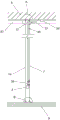
Fig. 1 is a back schematic view of a fabricated partition module weight reinforcement structure according to an embodiment of the present invention;
fig. 2 is a schematic front view of a weight reinforcement structure of an assembled partition wall module according to an embodiment of the present invention;
fig. 3 is a schematic side view of a fabricated partition module weight reinforcement structure according to an embodiment of the present invention;
fig. 4 is a schematic side view of a conventional partition wall module according to an embodiment of the present invention;
fig. 5 is an enlarged view of the structure at a in fig. 4 according to an embodiment of the present invention;
fig. 6 is an enlarged view of a structure at B in fig. 4 according to an embodiment of the present invention.
In the figure: 1. a keel frame; 2. reinforcing the keel; 3. a support member; 4. hanging a plate; 5. uploading firmware; 6. a firmware-down part; 7. plaque; 8. a top layer; 9. a bottom layer; 11. a top keel; 12. a bottom keel; 13. a transverse keel; 14. a vertical keel; 21. a cross beam; 22. erecting a beam; 31. a wire passing box; 32. a switch box; 33. a hose; 34. a junction box; 35. a conduit; 36. a blocking cover; 81. and (6) hanging a top layer.
Detailed Description
To make the purpose, technical solution and advantages of the embodiments of the present invention clearer, the technical solution in the embodiments of the present invention will be clearly and completely described below with reference to the accompanying drawings in the embodiments of the present invention, and obviously, the described embodiments are some, but not all, embodiments of the present invention. Based on the embodiments in the present invention, all other embodiments obtained by a person skilled in the art without creative efforts belong to the protection scope of the present invention.
In order to solve the problem, the utility model provides an assembled partition wall module heavy object reinforced structure, please refer to fig. 1, fig. 2, fig. 3, fig. 4, fig. 5, fig. 6, mainly including consolidating fossil fragments 2, support piece 3, hang dress board 4, many are consolidated fossil fragments 2 and are parallelly arranged and stand in top layer 8, between the bottom 9, a plurality of support piece 3 transversely erect between consolidating fossil fragments 2 and be connected with the fossil fragments frame 1 of both sides and form bearing frame, hang dress board 4 and be located bearing frame's front and two piece at least reinforcement fossil fragments 2 rigid couplings, and hang the rigid coupling position of dress board 4 and support piece 3's the position of erectting and do not overlap.
The utility model discloses a reinforced structure when using, can take the lead to accomplish reinforced structure's frame mount, again in proper order to the fossil fragments frame 1 of both sides installation standard partition wall. The keel frame 1 can be filled with glass wool, and the bearing frame is internally treated in the same way. When the decoration plate 7 is laid, the mounting area of the hanging and carrying plate 4 is removed from the bearing frame, and other positions can be laid together with the keel frame 1, or a non-standard decoration plate 7 is cut out for laying.
The keel frame 1 comprises a top keel 11, a bottom keel 12, a transverse keel 13 and a vertical keel 14, wherein the vertical keel 14 is provided with a through hole, so that the transverse keel 13 can be inserted into the vertical keel 14; the grooves of the top keel 11 and the bottom keel 12 are oppositely arranged, and the upper end and the lower end of the vertical keel 14 are respectively inserted into the grooves of the top keel 11 and the bottom keel 12.
Specifically, the top keel 11 comprises a group of L-shaped upper clamping pieces, each upper clamping piece comprises an upper inner clamping piece and an upper outer clamping piece, and the upper inner clamping pieces and the upper outer clamping pieces are fixed on the top layer 8 at intervals in parallel, so that a groove can be formed between the upper inner clamping pieces and the upper outer clamping pieces; the top keel 11 is inverted to form a top groove, and the upper ends of the vertical keels 14 are clamped in the top groove; the bottom keel 12 comprises a group of L-shaped lower clamping pieces, each lower clamping piece comprises a lower inner clamping piece and a lower outer clamping piece, and the lower inner clamping pieces and the lower outer clamping pieces are fixed on the bottom layer 9 at intervals in parallel, so that a groove can be formed between the lower inner clamping pieces and the lower outer clamping pieces; the bottom keel 12 is upright to form a bottom groove, and the lower ends of the vertical keels 14 are clamped into the bottom groove. The width of the groove is not less than the width of the vertical keel 14, so that the two ends of the vertical keel 14 can be inserted into the top keel 11 and the bottom keel 12 respectively.
It can be understood that a keel frame 1 can include a plurality of vertical keels 14, and through holes on the vertical keels 14 in the keel frame 1 are arranged at the same height; the vertical keels 14 at the two sides of the keel frame 1 are edge-closing keels, and no through hole is formed in the edge-closing keels. The grooves of the two edge-closing keels are oppositely arranged, so that the two ends of the transverse keel 13 are respectively inserted into the grooves of the edge-closing keels on the two sides.
The embodiment of the utility model provides an in, the downward bending type in both ends of support piece 3 becomes butt board, the butt board at support piece 3's both ends respectively with the roof fixed connection who is located the limit fossil fragments of the fossil fragments frame 1 of bearing frame both sides, can make and establish the relation of connection between fossil fragments frame 1 and the bearing frame, be favorable to improving the installation stability of standard partition wall.
In the utility model, the height of the hanging plate 4 can be designed according to actual requirements, and as an embodiment, the hanging plate 4 can be directly fixed on the reinforcing keels 2 and fixed with at least two reinforcing keels 2, so that the bearing stability of the hanging plate 4 is ensured; the form is suitable for a narrower hanging structure; as another embodiment, the cross beams 21 and the vertical beams 22 can be arranged at the fixed connection positions of the hanging plate 4 and the bearing frame, the two cross beams 21 are transversely and fixedly connected with the reinforcing keels 2, the two ends of the vertical beam 22 are respectively and fixedly connected with the two cross beams 21, the two cross beams 21 can provide wider fixed connection positions for the hanging plate 4, and meanwhile, the structural strength of the hanging plate 4 can be enhanced, so that the structure of the hanging plate 4 does not excessively deform when a heavy object is loaded; this form is suitable for longer hanging structure.
It can be understood that both ends of the cross beam 21 can be respectively fixedly connected with the keel frames 1 positioned at both sides of the bearing frame, and the structural stability of the keel frames 1 at both sides can be synchronously enhanced. The front end surfaces of the cross beam 21 and the vertical beam 22 are flush with the front surface of the keel frame 1, so that the hanging plate 4 fixedly connected to the front end surface of the cross beam 21 and the decorative plate 7 laid on the front surface of the keel frame 1 can be flush and butted; the hanging plate 4 may be covered with a trim plate 7, if necessary.
The embodiment of the utility model provides an in, support piece 3 erects between reinforcing keel 2, as an embodiment, can seted up the perforating hole on reinforcing keel 2 for support piece 3 can follow the perforating hole and peg graft a plurality of reinforcing keels 2 in proper order, accomplishes reinforcing keel 2 and support piece 3's basic structure and builds. As another embodiment, the reinforcing keels 2 are disposed in front of the supporting members 3 in a staggered manner and are fixedly connected to the supporting members 3, and the front surfaces of the reinforcing keels 2 are flush with the keel frames 1 on both sides.
A plurality of support pieces 3 are distributed between the reinforced keels 2, a wire passing box 31 and a switch box 32 can be installed on the support pieces, and a wire pipe 35 is arranged between the wire passing box 31 and the switch box 32 for butt joint and communication, so that cables can be conveniently laid.
At least one support piece 3 is located the top of consolidating fossil fragments 2, is provided with on the support piece 3 and crosses line box 31, crosses line box 31 and is located the furred ceiling layer 81 of top layer 8 for cross line box 31 and can dock the intercommunication with branch box 34 in the furred ceiling layer 81.
The wire passing box 31 is provided with a butt joint pipe in the ceiling layer 81, the butt joint pipe can be formed by a wire pipe 35, and a sealing cover 36 is arranged at the port of the wire passing box 31 for fixing. The butt joint pipe and the distribution box 34 can be in butt joint communication through a hose 33.
The keel structure is characterized by further comprising at least one supporting piece 3 positioned at the lower part of the reinforcing keel 2, a switch box 32 is arranged on the supporting piece 3, the switch box 32 is positioned below the top layer 8, the external switch box 32 is convenient for external personnel to directly operate, and a socket, a transmission interface and the like can be installed in the switch box 32.
In the embodiment of the utility model, a group of L-shaped upper fixing pieces 5 are arranged at the upper end of the reinforcing keel 2, and two upper fixing pieces 5 are respectively arranged at the two sides of the top end of the reinforcing keel 2 and are fixedly connected with the top layer 8; the lower extreme of consolidating fossil fragments 2 is provided with the lower firmware 6 of a set of L type, and two lower firmware 6 are located the both sides of consolidating fossil fragments 2 bottom respectively and with bottom 9 rigid couplings.
Specifically, the apex angle butt joint of going up firmware 5 connects to the butt joint angle department of consolidating fossil fragments and top layer 8, and the horizontal right-angle board of going up firmware 5 passes through expansion bolts with top layer 8 and fixes, and the vertical right-angle board of going up firmware 5 passes through the bolt fastening with consolidating fossil fragments 2. Furthermore, the vertical right-angle plates of the two upper fixing pieces 5 arranged on the two sides of the reinforced keel 2 can share one bolt to realize fixed connection. The lower firmware 6 can be similarly set.
The above-described embodiments can be implemented individually or in various combinations, and such variations are within the scope of the present invention.
It should be noted that, in this document, relational terms such as first and second, and the like are used solely to distinguish one entity or action from another entity or action without necessarily requiring or implying any actual such relationship or order between such entities or actions. Also, the terms "comprises," "comprising," or any other variation thereof, are intended to cover a non-exclusive inclusion, such that a process, method, article, or apparatus that comprises a list of elements does not include only those elements but may include other elements not expressly listed or inherent to such process, method, article, or apparatus. Without further limitation, an element defined by the phrase "comprising a component of 8230means that the element does not exclude the presence of another like element in a process, method, article, or apparatus that comprises the element.
The foregoing is a more detailed description of the invention, taken in conjunction with the specific preferred embodiments thereof, and it is not intended to limit the invention to the specific embodiments thereof. To the utility model belongs to the technical field of ordinary technical personnel, do not deviate from the utility model discloses under the prerequisite of design, can also make a plurality of simple deductions or replacement, all should regard as belonging to the utility model discloses a protection scope.
Claims (10)
1. The utility model provides an assembled partition wall module heavy object reinforced structure, its characterized in that, is including consolidating fossil fragments (2), support piece (3), hanging board (4), many consolidate fossil fragments (2) and set up in parallel and stand between top layer (8), bottom (9), and is a plurality of support piece (3) transversely erect in consolidate between fossil fragments (2) and be connected with keel frame (1) of both sides and form bearing frame, hanging board (4) are located bearing frame's front and at least two consolidate fossil fragments (2) rigid coupling, just the rigid coupling position of hanging board (4) with the position of erectting of support piece (3) does not overlap.
2. The weight reinforcement structure for the fabricated partition wall module according to claim 1, wherein the keel frame (1) comprises a top keel (11), a bottom keel (12), a cross keel (13) and a vertical keel (14), the vertical keel (14) is provided with a through hole, so that the cross keel (13) can be inserted into the vertical keel (14); the grooves of the top keel (11) and the bottom keel (12) are oppositely arranged, and the upper end and the lower end of the vertical keel (14) are respectively inserted into the grooves of the top keel (11) and the bottom keel (12).
3. The weight reinforcement structure for the assembled partition wall module according to claim 2, wherein the vertical keels (14) further comprise edge-closing keels at two sides of the keel frame (1), and grooves of the two edge-closing keels are oppositely arranged, so that two ends of the transverse keel (13) are respectively inserted into the grooves of the edge-closing keels at two sides.
4. The fabricated partition module weight reinforcement structure of claim 3, wherein two ends of the supporting member (3) are bent downwards to form abutting plates, and the abutting plates at two ends of the supporting member (3) are respectively fixedly connected with the top plates of the edge keel of the keel frame (1) at two sides of the bearing frame.
5. The weight reinforcement structure for the fabricated partition wall module is characterized in that cross beams (21) and vertical beams (22) are arranged at the fixing positions of the bearing frame and the hanging plates (4), two cross beams (21) are transversely fixed with a plurality of reinforcement keels (2), two ends of each vertical beam (22) are respectively fixed with the two cross beams (21), and two ends of each cross beam (21) are respectively fixed with keel frames (1) positioned at two sides of the bearing frame; the hanging plate (4) is fixed on the two cross beams (21).
6. The fabricated partition module weight reinforcement structure of claim 1, wherein the reinforcement keel (2) is provided with a through hole, so that the support member (3) can be sequentially inserted into a plurality of reinforcement keels (2) along the through hole.
7. An assembled partition module weight reinforcement structure according to claim 1, characterized in that the reinforcement keel (2) is arranged in front of the support member (3) and fixedly connected to the support member (3), and the front surface of the reinforcement keel (2) is flush with the keel frames (1) on both sides.
8. The fabricated partition module weight reinforcement structure of claim 1, wherein the support member (3) is located at the top end of the reinforcement keel (2), the support member (3) is provided with a wire box (31), and the wire box (31) is located in a ceiling layer (81) of the top layer (8), so that the wire box (31) can be in butt communication with a wire distribution box (34) in the ceiling layer (81).
9. An assembled partition module weight reinforcement structure according to claim 1, characterized in that the support member (3) is located at the lower part of the reinforcement keel (2), and a switch box (32) is arranged on the support member (3), and the switch box (32) is located under the top layer (8).
10. The weight reinforcement structure for the fabricated partition module according to claim 1, wherein a group of L-shaped upper fixing pieces (5) are arranged at the upper end of the reinforcing keel (2), and two upper fixing pieces (5) are respectively arranged at two sides of the top end of the reinforcing keel (2) and fixedly connected with the top layer (8); the lower extreme of consolidating fossil fragments (2) is provided with lower firmware (6) of a set of L type, two firmware (6) branch is located down consolidate both sides of fossil fragments (2) bottom and with bottom (9) rigid coupling.
Priority Applications (1)
| Application Number | Priority Date | Filing Date | Title |
|---|---|---|---|
| CN202222072042.9U CN218780002U (en) | 2022-08-08 | 2022-08-08 | Heavy object reinforcing structure of assembled partition wall module |
Applications Claiming Priority (1)
| Application Number | Priority Date | Filing Date | Title |
|---|---|---|---|
| CN202222072042.9U CN218780002U (en) | 2022-08-08 | 2022-08-08 | Heavy object reinforcing structure of assembled partition wall module |
Publications (1)
| Publication Number | Publication Date |
|---|---|
| CN218780002U true CN218780002U (en) | 2023-03-31 |
Family
ID=85708671
Family Applications (1)
| Application Number | Title | Priority Date | Filing Date |
|---|---|---|---|
| CN202222072042.9U Active CN218780002U (en) | 2022-08-08 | 2022-08-08 | Heavy object reinforcing structure of assembled partition wall module |
Country Status (1)
| Country | Link |
|---|---|
| CN (1) | CN218780002U (en) |
-
2022
- 2022-08-08 CN CN202222072042.9U patent/CN218780002U/en active Active
Similar Documents
| Publication | Publication Date | Title |
|---|---|---|
| CN110512790B (en) | High and large space multi-curvature suspended ceiling structure and construction method thereof | |
| GB1477754A (en) | Prefabricated buildings | |
| CN108661178A (en) | A kind of Combined container house room | |
| EP0306463B1 (en) | Suspended ceiling structure | |
| CN218780002U (en) | Heavy object reinforcing structure of assembled partition wall module | |
| US3786602A (en) | Modular ceiling assembly | |
| WO2018167555A2 (en) | High strength grid member for suspended ceilings | |
| CN216973984U (en) | Pull rod supporting and decorating system for sun-shading truss of station house | |
| CN115306176A (en) | Heavy object reinforcing structure of assembled partition wall module | |
| CN113622581B (en) | Special-shaped ceiling formed by combining triangular grating splicing units and installation method | |
| CN218492913U (en) | Prefabricated wall module of assembled pipeline | |
| CN212317254U (en) | Large-span curtain wall system | |
| CN109322435B (en) | Smallpox system | |
| CN207827663U (en) | A kind of single-row staircase decorative board mounting structure and staircase | |
| CN209066794U (en) | A kind of fastener veneer wall system | |
| KR20180125692A (en) | Modular unit for container | |
| CN207727811U (en) | A kind of steel wire keel partition wall fixed structure | |
| CN220414512U (en) | Top plate for integrated house | |
| CN211666080U (en) | Electrical pre-embedded structure of light partition wall | |
| CN220341980U (en) | Fixing structure for electromechanical pipeline of high-low difference floor roof | |
| CN211239226U (en) | Electrical socket mounting structure | |
| CN211690983U (en) | Floor board frame and floor board structure | |
| CN115370084A (en) | Prefabricated background wall module for assembly type pipeline and installation method of prefabricated background wall module | |
| CN218508875U (en) | Adjustable precast concrete molding hanging plate system | |
| CN220394973U (en) | Building roof and modularized building system |
Legal Events
| Date | Code | Title | Description |
|---|---|---|---|
| GR01 | Patent grant | ||
| GR01 | Patent grant |