CN218747393U - Processing jig with vacuum profiling positioning structure - Google Patents
Processing jig with vacuum profiling positioning structure Download PDFInfo
- Publication number
- CN218747393U CN218747393U CN202223313128.2U CN202223313128U CN218747393U CN 218747393 U CN218747393 U CN 218747393U CN 202223313128 U CN202223313128 U CN 202223313128U CN 218747393 U CN218747393 U CN 218747393U
- Authority
- CN
- China
- Prior art keywords
- fixedly provided
- fixed
- tool
- worm
- base
- Prior art date
- Legal status (The legal status is an assumption and is not a legal conclusion. Google has not performed a legal analysis and makes no representation as to the accuracy of the status listed.)
- Active
Links
Images


Landscapes
- Jigs For Machine Tools (AREA)
Abstract
The utility model relates to a tool technical field just discloses a processing tool with vacuum profile modeling location structure, the on-line screen storage device comprises a base, the top fixed mounting of base has quantity to be two and be the bracing piece that bilateral symmetry distributes, two the inboard of bracing piece is all rotated and is connected with the rotation and is connected with the pivot, two relative one side fixed mounting of pivot has same fixed frame. This processing tool with vacuum profile modeling location structure possesses the advantage such as being convenient for adjust the direction of processing, has solved at some electronic processing factory, need assemble not unidimensional work piece, need assist the equipment with the help of the tool, to various a small amount of production modes, often need use a plurality of tools, traditional tool can't be adjusted according to actual need, cause the shortcoming that manufacturing cost improved on the contrary, and the unable multi-angle of traditional tool is adjusted, the inconvenient problem of use operation.
Description
Technical Field
The utility model relates to a tool technical field specifically is a processing tool with vacuum profile modeling location structure.
Background
The jig is a large tool for carpenters, ironmen, pincers, machines, electric controls and other handicrafts, and is mainly used as a tool for assisting in controlling positions or actions (or both), and the jig can be divided into a process assembly jig, a project test jig and a circuit board test jig.
In some electronic processing factory, need assemble the work piece of unidimensional not, need assist the equipment with the help of the tool, to various a small amount of production modes, often need use a plurality of tools, traditional tool can't adjust according to actual need, causes the shortcoming that manufacturing cost improves on the contrary, and the unable multi-angle of traditional tool is adjusted, uses the operation inconvenient, so proposes a processing tool that has vacuum profile modeling location structure and solves the above-mentioned problem of proposing.
SUMMERY OF THE UTILITY MODEL
Technical problem to be solved
The utility model provides a not enough to prior art, the utility model provides a processing tool with vacuum profile modeling location structure possesses the advantage such as being convenient for adjust the direction of processing, solved at some electronic processing factory, need assemble the work piece of not unidimensional, need be with the help of tool auxiliary assembly, to various a small amount of production modes, often need use a plurality of tools, traditional tool can't be adjusted according to actual need, cause the shortcoming that manufacturing cost improved on the contrary, and the unable multi-angle of traditional tool is adjusted, use the inconvenient problem of operation.
(II) technical scheme
The utility model provides an above-mentioned technical problem's technical scheme as follows: the utility model provides a processing tool with vacuum profile modeling location structure, includes the base, the top fixed mounting of base has quantity to be two and be the bracing piece that bilateral symmetry distributes, two the inboard of bracing piece is all rotated and is connected with the rotation and is connected with the pivot, two relative one side fixed mounting of pivot has same fixed frame, the inboard fixed mounting of fixed frame has quantity to be two and be the slide bar that bilateral symmetry distributes, the top fixed mounting of fixed frame has the cylinder, the output fixed mounting of cylinder has the slide that is located two slide bar outsides, the bottom of slide is rotated and is connected with first centre gripping dish, the bottom fixed mounting of fixed frame has fixed storehouse, the inner chamber diapire fixed mounting of fixed storehouse has the motor, the output fixed mounting worm of motor, the inner chamber diapire fixed mounting of worm fixed storehouse has the worm wheel, worm wheel and worm intermeshing, the top fixed mounting of worm wheel has one end to extend to the major axis at fixed storehouse top, the top fixed mounting of major axis has second centre gripping dish, two the equal threaded connection screw rod in top of bracing piece.
The utility model has the advantages that: the workpiece is placed between the first clamping disc and the second clamping disc, the air cylinder is started to enable the sliding plate to move downwards along the two sliding rods, the workpiece is clamped, the motor is started to enable the worm to drive the worm wheel to rotate, the worm wheel drives the workpiece to transversely rotate through the long shaft, the two screw rods are driven to rotate, the fixing frame is rotated to adjust the longitudinal angle of the workpiece, and the workpiece is enabled to be in contact with the rotating shaft to be limited by rotating the two screw rods.
This processing tool with vacuum profile modeling location structure has possessed the advantage of being convenient for adjust the machine direction.
On the basis of the technical scheme, the utility model discloses can also do following improvement.
Furthermore, the rear side of the worm is rotatably connected with the fixed bin, and the sliding plate is slidably connected with the two sliding rods.
Adopt above-mentioned further scheme's beneficial effect to be connected through worm wheel and fixed storehouse rotation, make worm pivoted more stable, through slide and slide bar sliding connection, can make the slide from top to bottom along the slide bar.
Furthermore, the bottom of base fixed mounting has the slipmat, the slipmat is with base looks adaptation.
Adopt above-mentioned further scheme's beneficial effect be, can prevent through the slipmat that the base from sliding.
Furthermore, the outer side of the fixed bin is provided with four heat dissipation holes.
Adopt above-mentioned further scheme's beneficial effect to be, can prevent through the louvre that the inside high temperature of motor.
Further, a rotary table is fixedly mounted at the top of the screw, and an anti-skid groove is formed in the outer side of the rotary table.
Adopt the beneficial effect of above-mentioned further scheme to be convenient for rotate the screw rod through the carousel, the carousel is convenient for rotate to multiplicable hand frictional force in antiskid groove.
Further, two the interval and the fixed frame looks adaptation of bracing piece, two the screw rod contacts with the pivot.
The beneficial effect who adopts above-mentioned further scheme is that, the fixed frame is convenient for rotate to the interval and the fixed frame looks adaptation of two bracing pieces, and two screw rods contact with the pivot, are convenient for carry on spacingly through the screw rod to the pivot.
Drawings
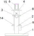
FIG. 1 is a schematic structural view of the present invention;
FIG. 2 is a side view of the connecting structure of the cylinder and the slide plate of the present invention;
FIG. 3 is a front view of the connection structure of the fixing frame and the fixing bin of the present invention;
fig. 4 is a side view of the connection structure of the support rod and the rotating shaft of the present invention.
In the figure: 1. a base; 2. a support bar; 3. a rotating shaft; 4. a fixing frame; 5. a slide bar; 6. a cylinder; 7. a slide plate; 8. a first chuck plate; 9. fixing the bin; 10. a motor; 11. a worm; 12. a worm gear; 13. a long axis; 14. a second chuck plate; 15. a screw.
Detailed Description
The technical solutions in the embodiments of the present invention will be described clearly and completely with reference to the accompanying drawings in the embodiments of the present invention, and it is obvious that the described embodiments are only some embodiments of the present invention, not all embodiments. Based on the embodiments in the present invention, all other embodiments obtained by a person skilled in the art without creative work belong to the protection scope of the present invention.
In the embodiment, as shown in fig. 1-4, a processing jig with a vacuum profiling positioning structure, the utility model discloses a base 1, the top of base 1 is fixedly provided with two support rods 2 which are distributed bilaterally symmetrically, the inner sides of the two support rods 2 are rotatably connected with a rotating shaft 3, one opposite side of the two rotating shafts 3 is fixedly provided with a fixed frame 4, the inner side of the fixed frame 4 is fixedly provided with two slide rods 5 which are distributed bilaterally symmetrically, the top of the fixed frame 4 is fixedly provided with a cylinder 6, the output end of the cylinder 6 is fixedly provided with a sliding plate 7 which is positioned at the outer side of the two slide rods 5, the bottom of the sliding plate 7 is rotatably connected with a first clamping disc 8, the bottom of the fixed frame 4 is fixedly provided with a fixed bin 9, the bottom wall of the inner cavity of the fixed bin 9 is fixedly provided with a motor 10, the output end of the motor 10 is fixedly provided with a worm 11, the bottom wall of the inner cavity of the worm fixed bin 9 is fixedly provided with a worm wheel 12, the worm wheel 12 is mutually meshed with a worm 11, the top of the worm wheel 12 is fixedly provided with a long shaft 13, one end of which extends to the top of the fixed bin 9, the top of the long shaft 13 is fixedly provided with a second clamping disc 14, and the top of the two support rods 2 are connected with a screw 15;
the rear side of the worm 11 is rotationally connected with the fixed bin 9, and the sliding plate 7 is slidably connected with the two sliding rods 5;
the worm 11 is rotatably connected with the fixed bin 9, so that the worm 11 rotates more stably, and the sliding plate 7 can slide up and down along the sliding rod 5 through the sliding connection of the sliding plate 7 and the sliding rod 5;
the bottom of the base 1 is fixedly provided with an anti-skid pad, and the anti-skid pad is matched with the base 1;
the friction force at the bottom of the base 1 can be increased through the anti-slip mat, so that the base 1 is prevented from sliding in use;
the outer side of the fixed bin 9 is provided with four heat dissipation holes;
the heat inside the fixed bin 9 can be dissipated through the heat dissipation holes, so that the motor 10 can be prevented from being too high in temperature when in use and influencing work;
a rotary table is fixedly arranged at the top of the screw 15, and an anti-skidding groove is formed in the outer side of the rotary table;
the screw 15 is convenient to rotate through the turntable, the anti-slip groove can increase the friction force of hands, and the turntable is convenient to rotate;
the space between the two support rods 2 is matched with the fixed frame 4, and the two screw rods 15 are in contact with the rotating shaft 3;
the interval and the fixed frame 4 looks adaptation of two bracing pieces 2 are convenient for rotate fixed frame 4, and two screw rods 15 contact with pivot 3, are convenient for carry on spacingly through screw rod 15 to pivot 3.
The working principle is as follows:
the first step is as follows: placing a workpiece between the first clamping disc 8 and the second clamping disc 14, and starting the air cylinder 6 to enable the sliding plate 7 to move downwards along the two sliding rods 5 to clamp the workpiece;
the second step: starting the motor 10 to enable the worm 11 to drive the worm wheel 12 to rotate, and the worm wheel 12 drives the workpiece to transversely rotate through the long shaft 13;
the third step: the two screw rods 15 are driven, the fixing frame 4 is rotated to adjust the longitudinal angle of the workpiece, and the two screw rods 15 are rotated to be in contact with the rotating shaft 3 to limit the position.
It should be noted that, in this document, relational terms such as first and second, and the like are used solely to distinguish one entity or action from another entity or action without necessarily requiring or implying any actual such relationship or order between such entities or actions. Also, the terms "comprises," "comprising," or any other variation thereof, are intended to cover a non-exclusive inclusion, such that a process, method, article, or apparatus that comprises a list of elements does not include only those elements but may include other elements not expressly listed or inherent to such process, method, article, or apparatus. Without further limitation, an element defined by the phrase "comprising a … …" does not exclude the presence of another identical element in a process, method, article, or apparatus that comprises the element.
Although embodiments of the present invention have been shown and described, it will be appreciated by those skilled in the art that changes, modifications, substitutions and alterations can be made in these embodiments without departing from the principles and spirit of the invention, the scope of which is defined in the appended claims and their equivalents.
Claims (6)
1. The utility model provides a processing tool with vacuum profile modeling location structure, includes base (1), its characterized in that: the top of the base (1) is fixedly provided with two supporting rods (2) which are distributed in a bilateral symmetry manner, the inner sides of the two supporting rods (2) are rotatably connected with rotating shafts (3), one opposite side of the two rotating shafts (3) is fixedly provided with the same fixed frame (4), the inner side of the fixed frame (4) is fixedly provided with two slide bars (5) which are distributed in bilateral symmetry, the top of the fixed frame (4) is fixedly provided with a cylinder (6), the output end of the cylinder (6) is fixedly provided with a sliding plate (7) positioned at the outer side of the two sliding rods (5), the bottom of the sliding plate (7) is rotationally connected with a first clamping disc (8), a fixed bin (9) is fixedly arranged at the bottom of the fixed frame (4), a motor (10) is fixedly arranged on the bottom wall of the inner cavity of the fixed bin (9), the output end of the motor (10) is fixedly provided with a worm (11), a worm wheel (12) is fixedly arranged on the bottom wall of the inner cavity of the fixed bin (9), the worm wheel (12) is meshed with the worm (11), the top of the worm wheel (12) is fixedly provided with a long shaft (13) one end of which extends to the top of the fixed bin (9), the top of major axis (13) fixed mounting have second centre gripping dish (14), two equal threaded connection screw rod (15) in top of bracing piece (2).
2. The processing jig with the vacuum profiling positioning structure as claimed in claim 1, wherein: the rear side of the worm (11) is rotatably connected with the fixed bin (9), and the sliding plate (7) is slidably connected with the two sliding rods (5).
3. The processing jig with the vacuum profiling positioning structure as claimed in claim 1, wherein: the bottom of base (1) is fixed with the slipmat, the slipmat is with base (1) looks adaptation.
4. The processing jig with the vacuum profiling positioning structure as claimed in claim 1, wherein: the outer side of the fixed bin (9) is provided with four heat dissipation holes.
5. The processing jig with the vacuum profiling positioning structure as claimed in claim 1, wherein: the top of the screw rod (15) is fixedly provided with a turntable, and the outer side of the turntable is provided with an anti-slip groove.
6. The processing jig with the vacuum profiling positioning structure as claimed in claim 1, wherein: two the interval and the fixed frame (4) looks adaptation of bracing piece (2), two screw rod (15) contact with pivot (3).
Priority Applications (1)
| Application Number | Priority Date | Filing Date | Title |
|---|---|---|---|
| CN202223313128.2U CN218747393U (en) | 2022-12-09 | 2022-12-09 | Processing jig with vacuum profiling positioning structure |
Applications Claiming Priority (1)
| Application Number | Priority Date | Filing Date | Title |
|---|---|---|---|
| CN202223313128.2U CN218747393U (en) | 2022-12-09 | 2022-12-09 | Processing jig with vacuum profiling positioning structure |
Publications (1)
| Publication Number | Publication Date |
|---|---|
| CN218747393U true CN218747393U (en) | 2023-03-28 |
Family
ID=85681629
Family Applications (1)
| Application Number | Title | Priority Date | Filing Date |
|---|---|---|---|
| CN202223313128.2U Active CN218747393U (en) | 2022-12-09 | 2022-12-09 | Processing jig with vacuum profiling positioning structure |
Country Status (1)
| Country | Link |
|---|---|
| CN (1) | CN218747393U (en) |
-
2022
- 2022-12-09 CN CN202223313128.2U patent/CN218747393U/en active Active
Similar Documents
| Publication | Publication Date | Title |
|---|---|---|
| CN218747393U (en) | Processing jig with vacuum profiling positioning structure | |
| CN212682513U (en) | Drilling machine convenient to clamping | |
| CN109434582B (en) | Work piece is polished and is used frock tool | |
| CN209775985U (en) | Clamping device of woodworking engraving machine | |
| CN214134042U (en) | Drilling equipment for machining hardware | |
| CN215356557U (en) | Gear machining clamping tool wide in application range | |
| CN215203305U (en) | Injection molding transfer device for automobile plastic parts | |
| CN215433678U (en) | Novel automatic grabbing device of mechanical arm | |
| CN212398844U (en) | Turning device for mechanical automation processing | |
| CN210817726U (en) | Aluminum product corner cut frock | |
| CN220372697U (en) | Device for realizing quick positioning of machine tool workbench | |
| CN220613067U (en) | Square workpiece clamping mechanism | |
| CN219404015U (en) | Positioning tool for mold processing | |
| CN218110225U (en) | Internal and external surface deburring device for lifting short section | |
| CN219725690U (en) | Grinding tool for mechanical production | |
| CN218808916U (en) | Automatic feeding device for three-coordinate measuring instrument | |
| CN220216783U (en) | Radial drilling machine capable of machining metal molds of different sizes | |
| CN211662236U (en) | Fixing device for router | |
| CN220073995U (en) | Vertical milling machine fixture | |
| CN220093825U (en) | Anchor clamps and digit control machine tool for digit control machine tool | |
| CN217344540U (en) | Clamping device of precision mold | |
| CN210755393U (en) | Plane milling machine with side presss from both sides function | |
| CN219926286U (en) | Clamp for wood processing | |
| CN220373598U (en) | Grooving device and double-shaft cylindrical polishing machine | |
| CN214023669U (en) | High-efficient stable numerically controlled fraise machine |
Legal Events
| Date | Code | Title | Description |
|---|---|---|---|
| GR01 | Patent grant | ||
| GR01 | Patent grant |