CN218742341U - Fiber crushing and pulping machine - Google Patents
Fiber crushing and pulping machine Download PDFInfo
- Publication number
- CN218742341U CN218742341U CN202223171598.XU CN202223171598U CN218742341U CN 218742341 U CN218742341 U CN 218742341U CN 202223171598 U CN202223171598 U CN 202223171598U CN 218742341 U CN218742341 U CN 218742341U
- Authority
- CN
- China
- Prior art keywords
- blade
- grind
- grinding
- mill
- cutting
- Prior art date
- Legal status (The legal status is an assumption and is not a legal conclusion. Google has not performed a legal analysis and makes no representation as to the accuracy of the status listed.)
- Active
Links
Images


Abstract
The utility model relates to a grind the field, disclose a fibre grinds pulp grinder, including connecting gradually actuating mechanism, grinding mechanism and the storage mechanism on locating the base, actuating mechanism includes inverter motor, pivot, grinds the mechanism and includes the casing, grinds the chamber, changes the mill, decides to grind, cuts big blade, little blade of cutting, three angular teeth reamers, the casing sets up with grinding the chamber and links to each other, sets up in the casing and changes the mill and decide to grind, decides to grind and be fixed in casing one side lateral wall, changes to grind and sets up in the pivot of running through the casing, changes to grind and decides to grind the matching setting, grinds the intracavity and sets up the big blade of cutting, cuts little blade, three angular teeth reamers, cuts big blade, cuts little blade cover and locates in the pivot, and three angular teeth reamers are fixed in the pivot tip. The device sets up the triangle tooth reamer, carries out preliminary cutting to the material, sets up the big blade of cutting and cuts little blade, carries out high-speed cutting to through the material, sets up the rotary mill, decides to grind, carries out final crushing to the material and grinds, improves the final fineness of grinding of material.
Description
Technical Field
The utility model relates to a grind the field, in particular to fiberizer is smashed to fibre.
Background
The existing method for grinding and pulping corncobs, gan Shuzha, traditional Chinese medicine residues, soybeans, cotton seeds, rapeseed, chicken livers, pig pancreases, pig cowhide scraps, leather chemical fiber cloth skin scraps and the like generally adopts a dry grinding method, the grinding efficiency of the device is low, the fineness of the final ground finished product needs to be improved, and the existing device consumes much electric quantity when being operated, and causes the problems of high temperature and dust flying in the use process of the machine.
The patent application of publication number CN202664137U discloses a high-speed pulping machine, the whole machine is arranged on a base, a motor on the base drives a driven belt pulley on a main shaft through a motor wheel and a triangular belt, the main shaft is connected and fixed with a fixing sleeve on the base through a bearing, a pulp cylinder is arranged outside the fixing sleeve, a pulp outlet is arranged at the bottom of the pulp cylinder, a flap valve is arranged on a pulp cylinder feeding hopper, a pulp cover is connected with the pulp cylinder through a hinge and fixed through a locking handle, an upper grinding sheet in the pulp cover and a lower grinding sheet in the pulp cylinder are fixed through a side fixing bolt, an adjusting handle is arranged outside the pulp cylinder, the bottom surface of the pulp cylinder adopts an inclined plane structure, and the pulp cover is fixed with the locking handle through a hinge. The large inclined bottom slurry cylinder is adopted, so that the cleaning is convenient, and the operation is more rapid and convenient.
The grinding process in the prior art is realized through the upper grinding plate and the lower grinding plate, the fineness of the ground part is to be improved, the main shaft is driven to rotate through the motor, the triangular belt and the driven belt pulley, the operating device grinds, and the purpose of saving electricity is difficult to realize.
For this reason, a new technical solution is needed to solve the above technical problems.
SUMMERY OF THE UTILITY MODEL
An object of the utility model is to provide a fibre is smashed and is ground thick liquid machine adopts the wet process to smash the mode that the thick liquid drawed, and the fineness of grind improves, and can economize on electricity, produces high temperature when also can avoiding the device to use, has the problem that the dust flies upward.
The utility model adopts the technical proposal that:
fiber crushing fiberizer, including connecting gradually actuating mechanism, grinding mechanism and the storage mechanism of locating on the base, actuating mechanism includes inverter motor, pivot, and grinding mechanism includes casing, grinding chamber, commentaries on classics mill, surely grinds, cuts big blade, little blade of cutting, triangular teeth reamer, the casing links to each other with grinding chamber and sets up, sets up in the casing commentaries on classics mill and surely grinds, decides to grind and is fixed in casing one side lateral wall, and the commentaries on classics mill sets up in the pivot of running through the casing, changes to grind and surely grinds the matching setting, grinds the intracavity and sets up the big blade of cutting, little blade of cutting, triangular teeth reamer, cuts big blade, cutting small blades cover and locates in the pivot, and triangular teeth reamer is fixed in shaft end portion, and storage mechanism includes the storage silo. When the device is used, the grinding effect is better, the fineness is higher after the materials are ground into pulp, and the power consumption is saved.
Furthermore, the variable frequency motor is connected with the rotating shaft through a coupler, a bearing seat is arranged outside the rotating shaft, an angle bearing is arranged between one end, close to the coupler, of the bearing seat and the rotating shaft, a deep groove bearing is arranged between the other end of the bearing seat and the rotating shaft, and the bearing seat is connected with the shell. The bearing block is internally provided with an angle bearing and a deep groove bearing, so that the rotating stability of the rotating shaft is improved.
Furthermore, the rotating shaft is provided with a sealing chamber in the shell, and the sealing chamber and the fixed mill are oppositely arranged on two sides of the shell. The rotating shaft is provided with a sealing chamber, so that the leakage of the materials in the shell in the grinding process is avoided.
Further, the length of the blade of the large cutting blade is larger than that of the blade of the small cutting blade, the large cutting blade and the small cutting blade are both provided with a plurality of blades, the blades of the large cutting blade are both positioned between the blades of the two adjacent small cutting blades, and the large cutting blade is arranged close to the fixed mill. Set up cutting big blade, cutting little blade, the material is through twice cutting, and the cutting effect is better, makes the material that gets into the grinding littleer, and follow-up thick liquid efficiency is higher.
Further, grind the discharge gate of chamber and storage silo bottom and pass through feed bin flange joint, the storage silo is bucket type feed bin. Storage silo bucket type, it is more convenient that the bottom material gets into the grinding chamber.
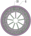
Further, the surface of the rotary mill is a stepped grinding surface which is sequentially convex, the fixed mill and the rotary mill are correspondingly provided with the stepped grinding surface which is sequentially concave, the rotary mill and the fixed mill are respectively provided with a trough I and a trough II, and the widths of the rotary mill and the fixed mill trough I and the trough II are gradually reduced from the center to the outside. Decide to grind and the unsmooth setting of commentaries on classics mill opposite face, and the opposite face sets up the silo, and the material of being convenient for is from the middle part through scissors, coarse crushing, well garrulous, the shearing crushing process who refines, and the edge grinding of deciding edge of rotation spills over gradually, and grinding effect is better.
Furthermore, the bottom of the base is provided with a base fixing foot.
Compared with the prior art, the utility model, following beneficial effect has:
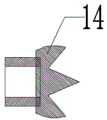
1. the utility model discloses the device sets up three angle tooth reamers, carries out preliminary cutting to the material after the material falls from the storage silo, and the follow-up step material cutting of being convenient for is thinner, and three angle tooth reamers locate the ejection of compact department of storage silo bottom, with the broken cutting such as holding a group, glue group, caking in the material, can avoid the material to block up before getting into the grinding step.
2. The utility model discloses the device sets up the big blade of cutting and cuts the little blade, carries out high-speed cutting to the process material, calls the tiny particle with the material breakage, makes the material get into smoothly and changes the mill and grind surely.
3. The utility model discloses the device sets up and changes the mill, decides the mill, carries out final crushing grinding to getting into the material, improves the final fineness of grind of material, and grinding efficiency is higher, and the effect is better.
4. The utility model discloses the device provides power through inverter motor, rotates through the pivot and realizes whole grinding operation, can save the power consumption.
5. The utility model discloses the device adopts the wet grinding to grind the mode that the thick liquid drawed, produces high temperature when can avoiding the device to use, and avoids the problem that the dust flies upward among the grinding process.
Drawings
The present invention will be described in further detail with reference to the accompanying drawings and specific embodiments.
Fig. 1 is a schematic structural view of the present invention;
FIG. 2 is a side view of the large cutting blade and the small cutting blade of the present invention;
FIG. 3 is a structural diagram of the triangular reamer of the present invention;
FIG. 4 is a structural diagram of the fixed mill of the present invention;
FIG. 5 is a structural diagram of the rotary grinder of the present invention;
fig. 6 is a schematic view of a fixed-abrasive feeding chute I of the utility model;
fig. 7 is a schematic diagram of the feeding chute ii of the rotary mill of the present invention.
Wherein: 1. a coupling; 2. an angle bearing; 3. a rotating shaft; 4. a bearing seat; 5. a deep groove bearing; 6. a sealed chamber; 7. a housing; 8. rotating and grinding; 9. fixed grinding; 10. a variable frequency motor; 11. a storage bin; 12. cutting a large blade; 13. cutting the small blade; 14. a triangular tooth reamer; 15. the bin is connected with a flange; 16. a base; 17. a base fixing leg; 18. a material groove I; 19. a material groove II; 20. a grinding chamber.
Detailed Description
As shown in fig. 1-7, fiber grinding pulp grinder, including connecting drive mechanism, grinding mechanism and the storage mechanism who locates on base 16 in proper order, base 16 bottom is equipped with the fixed foot 17 of frame, and drive mechanism includes inverter motor 10, pivot 3, and grinding mechanism includes casing 7, grinds chamber 20, changes mill 8, surely grinds 9, cuts big blade 12, cuts little blade 13, triangle tooth reamer 14, casing 7 links to each other with grinding chamber 20 and sets up, sets up in casing 7 and changes mill 8 and surely grind 9, decides that grind 9 is fixed in casing 7 one side lateral wall, changes mill 8 and sets up on the pivot 3 that runs through casing 7, changes mill 8 and surely grinds 9 and match the setting, sets up in grinding chamber 20 and cuts big blade 12, cuts little blade 13, triangle tooth reamer 14, cuts big blade 12, cuts little blade 13 cover and locates on pivot 3, triangle tooth reamer 14 is fixed in pivot 3 tip, and reamer mechanism includes storage silo 11, and grinding chamber 20 passes through the feed bin connection flange 15 with the discharge gate of storage silo 11 bottom and is connected, and storage silo 11 is hopper type feed bin. This device sets up triangular teeth reamer 14, and the material is carried out preliminary cutting to the material after falling from storage silo 11, and the follow-up step material cutting of being convenient for is thinner, and triangular teeth reamer 14 locates the ejection of compact department of storage silo 11 bottom, with the broken cutting such as holding a group in the material, gluing a group, caking, can avoid the material to block up before getting into the grinding step. The device is provided with a large cutting blade 12 and a small cutting blade 13, and is used for cutting materials at a high speed, crushing the materials and weighing small particles, so that the materials smoothly enter a rotary grinding mill for grinding. The device adopts the mode of wet process grinding thick liquid extraction, can avoid the device to produce high temperature when using, and avoids the problem that the dust flies upward in the grinding process.
The variable frequency motor 10 is connected with a rotating shaft 3 through a coupler 1, a bearing seat 4 is arranged outside the rotating shaft 3, an angle bearing 2 is arranged between one end, close to the coupler 1, of the bearing seat 4 and the rotating shaft 3, a deep groove bearing 5 is arranged between the other end of the bearing seat and the rotating shaft 3, and the bearing seat 4 is connected with a shell 7. The device provides power through inverter motor 10, rotates through pivot 3 and realizes whole grinding operation, can save the power consumption. The rotating shaft 3 is provided with a sealing chamber 6 in a shell 7, and the sealing chamber 6 and a fixed mill 9 are oppositely arranged at two sides of the shell 7. Establish seal chamber 6 on the pivot 3, avoid the material in the casing 7 to reveal at the grinding in-process.
As shown in fig. 2, the length of the large cutting blade 12 is greater than that of the small cutting blade 13, the large cutting blade 12 and the small cutting blade 13 are both provided with a plurality of blades, the blades of the large cutting blade 12 are both located between the blades of two adjacent small cutting blades 13, and the large cutting blade 12 is arranged close to the fixed grinder 9. The large cutting blade 12 and the small cutting blade 13 are arranged, the material is cut twice, the cutting effect is better, the material entering grinding is smaller, and the subsequent grinding efficiency is higher.
As shown in fig. 4-7, the surface of the rotary mill 8 is a stepped grinding surface which is convex in sequence, the fixed mill 9 is provided with a stepped grinding surface which is concave in sequence corresponding to the rotary mill 8, the grinding surfaces of the rotary mill 8 corresponding to the fixed mill 9 are provided with a trough i 18 and a trough ii 19 respectively, and the widths of the troughs i 18 and ii 19 of the rotary mill 8 and the fixed mill 9 are gradually reduced from the center to the outside. The device sets up and changes 8, surely grinds 9, carries out final crushing and grinding to getting into the material, improves the final fineness of grind of material, and grinding efficiency is higher, and the effect is better.
When the device is used, fiber slurry is firstly conveyed into a storage bin 11 through a pipeline, then enters an inlet of a grinding cavity 20 in a pulping machine through a self-flow, a variable frequency motor 10 drives a rotating shaft to rotate, a triangular tooth reamer 14 arranged at the inlet of the grinding cavity 20 is used for crushing and cutting cohesive masses, caking and the like in the fiber slurry, then the fiber slurry is combined into six cutter sets through a small three-blade cutter 13 and a large three-blade cutter 12 to be cut at a high speed to be crushed into small particles, and finally the fiber slurry enters a rotary mill to be ground and then discharged, wherein the stepped rotary mill comprises four shearing and crushing processes of scissors, coarse crushing, middle crushing, refining and the like, two groups of small three-blade cutters 13 and large three-blade cutters 12 at the inlet have a powerful shearing and material sucking function, and the device is more suitable for shearing, crushing, refining and conveying the high-viscosity fiber slurry.
The above-mentioned embodiments are only intended to describe the preferred embodiments of the present invention, but not to limit the scope of the present invention, and those skilled in the art should be able to make various modifications and improvements to the technical solution of the present invention without departing from the spirit of the present invention, and all such modifications and improvements are intended to be included within the scope of the present invention as defined in the appended claims.
Claims (7)
1. Fibre smashes fiberizer, including connecting gradually actuating mechanism, grinding mechanism and the storage mechanism of locating on the base, its characterized in that: actuating mechanism includes inverter motor, pivot, grinds the mechanism and includes casing, grinds the chamber, changes the mill, decides to grind, cuts big blade, little blade of cutting, three angular teeth reamer, the casing with grind the chamber and link to each other and set up, set up in the casing and change the mill with deciding to grind, decide to grind and be fixed in casing one side lateral wall, change the mill and set up in the pivot of running through the casing, change the mill and decide to grind the matching setting, grind the intracavity and set up big blade of cutting, little blade of cutting, three angular teeth reamer, cut big blade, cut the knife blade cover and locate in the pivot, three angular teeth reamer are fixed in shaft tip, and storage mechanism includes the storage silo.
2. A fiber pulverization refiner as claimed in claim 1, characterized in that: the variable frequency motor is connected with the rotating shaft through the coupler, a bearing seat is arranged outside the rotating shaft, an angle bearing is arranged between one end, close to the coupler, of the bearing seat and the rotating shaft, a deep groove bearing is arranged between the other end of the bearing seat and the rotating shaft, and the bearing seat is connected with the shell.
3. A fiber size refiner according to claim 1, wherein: the rotating shaft is provided with a sealing chamber in the shell, and the sealing chamber and the fixed mill are oppositely arranged on two sides of the shell.
4. A fiber pulverization refiner as claimed in claim 1, characterized in that: the length of the blade of the large cutting blade is larger than that of the blade of the small cutting blade, the large cutting blade and the small cutting blade are both provided with a plurality of blades, the blades of the large cutting blade are both positioned between the blades of the two adjacent small cutting blades, and the large cutting blade is arranged close to the fixed mill.
5. A fiber size refiner according to claim 1, wherein: the grinding cavity is connected with a discharge hole at the bottom of the storage bin through a bin connecting flange, and the storage bin is a hopper-shaped bin.
6. A fiber pulverization refiner as claimed in claim 1, characterized in that: the rotary grinding surface is a stepped grinding surface which is sequentially convex, the fixed grinding and the rotary grinding are correspondingly provided with the stepped grinding surface which is sequentially concave, the rotary grinding and the fixed grinding are respectively provided with a trough I and a trough II, and the widths of the rotary grinding and the fixed grinding trough I and the trough II are gradually reduced from the center to the outside.
7. A fiber pulverization refiner as claimed in claim 1, characterized in that: the bottom of the base is provided with a base fixing foot.
Priority Applications (1)
| Application Number | Priority Date | Filing Date | Title |
|---|---|---|---|
| CN202223171598.XU CN218742341U (en) | 2022-11-29 | 2022-11-29 | Fiber crushing and pulping machine |
Applications Claiming Priority (1)
| Application Number | Priority Date | Filing Date | Title |
|---|---|---|---|
| CN202223171598.XU CN218742341U (en) | 2022-11-29 | 2022-11-29 | Fiber crushing and pulping machine |
Publications (1)
| Publication Number | Publication Date |
|---|---|
| CN218742341U true CN218742341U (en) | 2023-03-28 |
Family
ID=85676376
Family Applications (1)
| Application Number | Title | Priority Date | Filing Date |
|---|---|---|---|
| CN202223171598.XU Active CN218742341U (en) | 2022-11-29 | 2022-11-29 | Fiber crushing and pulping machine |
Country Status (1)
| Country | Link |
|---|---|
| CN (1) | CN218742341U (en) |
-
2022
- 2022-11-29 CN CN202223171598.XU patent/CN218742341U/en active Active
Similar Documents
| Publication | Publication Date | Title |
|---|---|---|
| CN105750044A (en) | Spiral pulverizer | |
| CN209898123U (en) | High-efficient meat beating machine | |
| CN218742341U (en) | Fiber crushing and pulping machine | |
| CN220027252U (en) | Fodder grinder | |
| CN108934501A (en) | A kind of integrated straw millstone of environmental protection | |
| CN215029205U (en) | High-efficient hammer mill | |
| CN212975396U (en) | Reducing mechanism is used in processing of treatment vitiligo traditional chinese medicine | |
| CN207929391U (en) | A kind of Aquatic Feed Processing pulverizer | |
| CN105107582A (en) | Negative-pressure air-conveying screen-free plant material pulverizer | |
| CN207543677U (en) | A kind of novel corn straw millstone | |
| CN211363094U (en) | Plastic grinder | |
| CN214262197U (en) | A grind machine for medicine inspection | |
| CN213344150U (en) | Processing equipment for meat balls capable of quickly crushing raw materials | |
| CN211274848U (en) | Tea shearing and pulping machine | |
| CN210679283U (en) | Efficient crusher for rubber | |
| CN219092271U (en) | Replaceable auxiliary material crushing bin | |
| CN212629278U (en) | A kind of comminutor | |
| CN209406479U (en) | A kind of barren rock material pulverizer | |
| CN220346052U (en) | Direct-discharge type commercial garbage disposer | |
| CN215234633U (en) | Waste material reducing mechanism of printing labeling paper processing usefulness | |
| CN218796323U (en) | Rice milk grinder | |
| CN212218980U (en) | Crushing mechanism of powder grinding machine for plastic particle processing | |
| CN108093897A (en) | A kind of novel vertical stalk crasher | |
| CN217615205U (en) | Traditional Chinese medicine crushing device | |
| CN215029677U (en) | Animal remedy processing is with raw materials carousel formula multi-stage reduction device |
Legal Events
| Date | Code | Title | Description |
|---|---|---|---|
| GR01 | Patent grant | ||
| GR01 | Patent grant |