CN218723905U - Glass tube production laser diameter gauge - Google Patents
Glass tube production laser diameter gauge Download PDFInfo
- Publication number
- CN218723905U CN218723905U CN202222711793.0U CN202222711793U CN218723905U CN 218723905 U CN218723905 U CN 218723905U CN 202222711793 U CN202222711793 U CN 202222711793U CN 218723905 U CN218723905 U CN 218723905U
- Authority
- CN
- China
- Prior art keywords
- plate
- plectane
- shell
- slider
- glass tube
- Prior art date
- Legal status (The legal status is an assumption and is not a legal conclusion. Google has not performed a legal analysis and makes no representation as to the accuracy of the status listed.)
- Active
Links
Images


Classifications
-
- Y—GENERAL TAGGING OF NEW TECHNOLOGICAL DEVELOPMENTS; GENERAL TAGGING OF CROSS-SECTIONAL TECHNOLOGIES SPANNING OVER SEVERAL SECTIONS OF THE IPC; TECHNICAL SUBJECTS COVERED BY FORMER USPC CROSS-REFERENCE ART COLLECTIONS [XRACs] AND DIGESTS
- Y02—TECHNOLOGIES OR APPLICATIONS FOR MITIGATION OR ADAPTATION AGAINST CLIMATE CHANGE
- Y02P—CLIMATE CHANGE MITIGATION TECHNOLOGIES IN THE PRODUCTION OR PROCESSING OF GOODS
- Y02P40/00—Technologies relating to the processing of minerals
- Y02P40/50—Glass production, e.g. reusing waste heat during processing or shaping
- Y02P40/57—Improving the yield, e-g- reduction of reject rates
Landscapes
- Length Measuring Devices By Optical Means (AREA)
Abstract
The utility model discloses a glass manages production laser diameter measuring instrument, belong to the diameter measuring instrument field, which comprises an outer shell, shell up end left side position is provided with detects the groove, it is provided with laser to the board to detect groove both sides inner wall, it is provided with first layer board to detect the tank bottoms portion, shell up end right side position is provided with the display screen, shell front end left side position is provided with the rectangular plate, the rectangular plate outer lane is provided with adjustable slider, slider right side end top position is provided with the diaphragm, diaphragm up end head position is provided with the second layer board, through setting up the rectangular plate in shell one side, and then install adjustable slider, utilize slider installation diaphragm and second layer board simultaneously, the convenient glass pipe to various length carries out bearing and accomplishes the measurement, stand and fixed plate with adjustable setting up simultaneously at the diaphragm afterbody, the sponge bed course that utilizes the fixed plate bottom surface compresses tightly the glass pipe fixedly, and the cooperation ejector pad steadily promotes, the convenience is measured in order to each section of glass pipe.
Description
Technical Field
The utility model relates to a calliper field, in particular to glass manages production laser calliper appearance.
Background
The laser diameter measuring instrument measures the diameter of a material by adopting a laser scanning principle, can detect information such as the maximum diameter, the minimum diameter, the average diameter, the ellipticity and the like of the material in a real-time online nondestructive mode, can be used for non-contact measurement and control of the size of an object, such as the height, the edge, the diameter, the line diameter, the width, the gap, the inner diameter, the outer diameter and the like of a part, and is also suitable for quality inspection operation of a glass tube.
SUMMERY OF THE UTILITY MODEL
The utility model aims to provide a glass manages production laser diameter measuring appearance can effectively solve the problem in the background art.
In order to achieve the above purpose, the utility model adopts the technical proposal that:
the utility model provides a glass manages production laser diameter measuring instrument, includes the shell, shell up end left side position is provided with detects the groove, it is provided with laser to the board to detect groove both sides inner wall, it is provided with first layer board to detect the tank bottom portion, shell up end right side position is provided with the display screen, shell front end left side position is provided with the rectangular plate, the rectangular plate outer lane is provided with adjustable slider, slider right side end top position is provided with the diaphragm, diaphragm up end head position is provided with the second layer board, diaphragm up end afterbody position is provided with adjustable stand, the stand head is provided with the fixed plate, terminal surface head position is provided with the sponge bed course under the fixed plate.
Preferably, be swing joint between slider and the rectangular plate, the slider bottom corresponds the rectangular plate and is provided with the rectangular channel, the rectangular plate head passes the rectangular channel and is provided with the shrouding, the size of first layer board and second layer board equals, and highly the same, the sponge bed course is located second layer board top position.
Preferably, a pushing block is arranged on the end face of the outer side of the sliding block, the pushing block is connected with the sliding block through bonding, and a handle is arranged on the upper end face of the fixing plate.
Preferably, the transverse plate and the sliding block are integrally formed, the tail part of the transverse plate is provided with a round hole corresponding to the upright post, and the upright post is movably arranged in the round hole.
Preferably, the stand afterbody passes the round hole and is provided with the bottom plectane, the bottom plectane is fixed with the stand through bonding, stand outer lane bottom position is provided with down the plectane, the plectane is located bottom plectane top position down, stand outer lane top position is provided with the plectane, it is located the fixed plate lower position to go up the plectane, go up plectane and the equal movable mounting of plectane down at the stand outer lane, it is provided with the spring to go up between plectane and the lower plectane.
Preferably, a plurality of balls are arranged on the outer ring of the upper end face of the bottom circular plate, the balls are located on the outer ring of the upright post, and the tops of the balls and the lower end face of the lower circular plate are at the same height.
Compared with the prior art, the utility model discloses following beneficial effect has:
the utility model discloses in, through setting up the rectangular plate in shell one side, and then install adjustable slider, utilize slider installation diaphragm and second layer board simultaneously, the convenient glass pipe to various length carries out the bearing and accomplishes the measurement, sets up adjustable stand and fixed plate at the diaphragm afterbody simultaneously, utilizes the sponge bed course of terminal surface to compress tightly fixedly to the glass pipe under the fixed plate to the cooperation ejector pad carries out steady promotion, conveniently carries out orderly measurement to each section of glass pipe.
Drawings
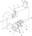
FIG. 1 is a schematic view of the overall structure of the present invention;
fig. 2 is a schematic view of a second pallet of the present invention;
FIG. 3 is a schematic view of the sponge cushion of the present invention;
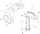
fig. 4 is a schematic view of the stand column of the present invention.
In the figure: 1. a housing; 2. a detection tank; 3. laser plate alignment; 4. a display screen; 5. a first pallet; 6. a rectangular plate; 7. a slider; 8. a transverse plate; 9. a second pallet; 10. a fixing plate; 11. a sponge cushion layer; 12. closing the plate; 13. a push block; 14. a column; 15. a rectangular groove; 16. a circular hole; 17. a grip; 18. a bottom circular plate; 19. an upper circular plate; 20. a lower circular plate; 21. a spring; 22. and a ball.
Detailed Description
In order to make the utility model realize, the technical means, the creation characteristics, the achievement purpose and the efficacy are easy to understand and understand, the utility model is further explained by combining the specific implementation mode.
As shown in fig. 1-4, a glass tube production laser diameter measuring instrument, including shell 1, 1 up end left side position of shell is provided with detects groove 2, it is provided with laser to board 3 to detect 2 both sides inner wall in groove, it is provided with first layer board 5 to detect 2 bottoms in groove, 1 up end right side position of shell is provided with display screen 4, 1 front end left side position of shell is provided with rectangular plate 6, 6 outer lanes of rectangular plate are provided with adjustable slider 7, 7 right side end top position of slider is provided with diaphragm 8, 8 up end head positions on diaphragm are provided with second layer board 9, 8 up end afterbody positions on diaphragm are provided with adjustable stand 14, 14 heads of stand are provided with fixed plate 10, the end head position is provided with sponge bed course 11 under fixed plate 10.
In this embodiment, in order to facilitate the movement of the slider 7, the slider 7 can move stably along the rectangular plate 6, and further the position of the glass tube is adjusted, so as to detect each section of the glass tube, the slider 7 is movably connected with the rectangular plate 6, the bottom of the slider 7 is provided with a rectangular groove 15 corresponding to the rectangular plate 6, the head of the rectangular plate 6 passes through the rectangular groove 15 and is provided with a sealing plate 12, the first supporting plate 5 and the second supporting plate 9 have the same size and the same height, the sponge cushion layer 11 is positioned above the second supporting plate 9, the outer side end face of the slider 7 is provided with a push block 13, the push block 13 is connected with the slider 7 through bonding, and the upper end face of the fixing plate 10 is provided with a handle 17;
in this embodiment, in order to adjust the height and angle of the fixing plate 10 and the sponge cushion 11, so that the fixing plate can be matched with the second support plate 9 to clamp the glass tube, and further ensure the stability of the glass tube during detection, the horizontal plate 8 and the slider 7 are integrally formed, the tail portion of the horizontal plate 8 is provided with a round hole 16 corresponding to the column 14, the column 14 is movably installed in the round hole 16, the tail portion of the column 14 passes through the round hole 16 and is provided with a bottom circular plate 18, the bottom circular plate 18 is fixed with the column 14 through adhesion, the bottom circular plate 20 is arranged at the bottom position of the outer ring of the column 14, the lower circular plate 20 is positioned above the bottom circular plate 18, the top position of the outer ring of the column 14 is provided with an upper circular plate 19, the upper circular plate 19 is positioned below the fixing plate 10, the upper circular plate 19 and the lower circular plate 20 are both movably installed at the outer ring of the column 14, a spring 21 is arranged between the upper circular plate 19 and the lower circular plate 20, a plurality of balls 22 are arranged at the outer ring position of the upper end face of the bottom circular plate 18, the balls 22 are positioned at the outer ring position of the outer ring of the column 14, and the lower circular plate 20 are at the same height.
It should be noted that, the utility model relates to a glass tube production laser diameter measuring instrument, when in actual use, firstly observe the length of the glass tube to be detected, if the glass tube is short tube, then directly place the glass tube at the position above the first supporting plate 5, then detect the data such as the diameter, the obtained data is displayed on the display screen 4, the detection can be completed by observing the data, if the glass tube is longer, the rectangular plate 6 and the slide block 7 at the outer ring can be found, then the push block 13 is pushed to drive the slide block 7 to slide along the rectangular plate 6, the slide block 7 simultaneously drives the transverse plate 8 and the second supporting plate 9 to move, then the head of the glass tube is placed above the first supporting plate 5, then the position is adjusted, the second supporting plate 9 reaches the position of the tail of the glass tube, then the glass tube is placed, the tail of the glass tube falls above the second supporting plate 9, thus the stability of the glass tube can be ensured, at this time, data can be observed for detection, if the detection and comparison of each section of the long tube are needed, the fixing plate 10 and the handle 17 above the transverse plate 8 can be found, then the fixing plate 10 is lifted by the handle 17 to drive the upright post 14 to move upwards, the upright post 14 drives the bottom circular plate 18 to move upwards, the bottom circular plate 18 presses the lower circular plate 20 above when moving, the lower circular plate 20 rises along with the lifting, the lower circular plate 20 presses the upper spring 21 when rising, the spring 21 is stressed and compressed until the height of the fixing plate 10 and the sponge cushion 11 is higher than that of the glass tube, then the handle 17 can be rotated to drive the fixing plate 10 and the upright post 14 to rotate, the upright post 14 drives the bottom circular plate 18 to rotate, the bottom circular plate 18 rotates on the lower end face of the lower circular plate 20 through the balls 22 on the upper end face, the friction resistance can be effectively reduced until the sponge cushion 11 reaches the position above the glass tube, then slowly loosening the handle 17 to slowly press the fixing plate 10, finally dropping the sponge cushion layer 11 on the surface of the glass tube, clamping and fixing the glass tube by matching with the second supporting plate 9, and then pushing the push block 13 to move at a constant speed, so that the glass tube can be driven to pass through the detection groove 2 at a constant speed to obtain data of each section of the glass tube, and detection and comparison are convenient.
The basic principles and the main features of the invention and the advantages of the invention have been shown and described above. It will be understood by those skilled in the art that the present invention is not limited to the above embodiments, and that the foregoing embodiments and descriptions are provided only to illustrate the principles of the present invention without departing from the spirit and scope of the present invention. The scope of the invention is defined by the appended claims and equivalents thereof.
Claims (6)
1. The utility model provides a glass manages production laser diameter measuring appearance, includes shell (1), shell (1) up end left side position is provided with detects groove (2), it is provided with laser to board (3) to detect groove (2) both sides inner wall, it is provided with first layer board (5) to detect groove (2) bottom, shell (1) up end right side position is provided with display screen (4), its characterized in that: the utility model discloses a shell (1) front end face left side position is provided with rectangular plate (6), rectangular plate (6) outer lane is provided with adjustable slider (7), slider (7) right side terminal surface top position is provided with diaphragm (8), terminal surface head position is provided with second layer board (9) on diaphragm (8), diaphragm (8) up end afterbody position is provided with adjustable stand (14), stand (14) head is provided with fixed plate (10), terminal surface head position is provided with sponge bed course (11) under fixed plate (10).
2. The glass tube production laser caliper according to claim 1, wherein: be swing joint between slider (7) and rectangular plate (6), slider (7) bottom corresponds rectangular plate (6) and is provided with rectangular channel (15), rectangular plate (6) head passes rectangular channel (15) and is provided with shrouding (12), first layer board (5) are equal with the size of second layer board (9), and highly the same, sponge bed course (11) are located second layer board (9) top position.
3. The glass tube production laser caliper according to claim 1, wherein: the outer side end face of the sliding block (7) is provided with a pushing block (13), the pushing block (13) is connected with the sliding block (7) through bonding, and the upper end face of the fixing plate (10) is provided with a handle (17).
4. The glass tube production laser caliper according to claim 1, wherein: the structure is characterized in that the transverse plate (8) and the sliding block (7) are integrally formed, a round hole (16) is formed in the tail part of the transverse plate (8) corresponding to the upright post (14), and the upright post (14) is movably arranged in the round hole (16).
5. The glass tube production laser caliper according to claim 4, wherein: the utility model discloses a safety valve, including stand (14), bottom plectane (18) are fixed with stand (14) through bonding, stand (14) outer lane bottom position is provided with down plectane (20), plectane (20) are located bottom plectane (18) top position down, stand (14) outer lane top position is provided with plectane (19), it is located fixed plate (10) below position to go up plectane (19), it is all movable mounting in stand (14) outer lane with lower plectane (20) to go up plectane (19), it is provided with spring (21) down between plectane (20) to go up plectane (19).
6. The glass tube production laser caliper according to claim 5, wherein: the outer ring of the upper end face of the bottom circular plate (18) is provided with a plurality of balls (22), the balls (22) are located at the outer ring of the upright post (14), and the tops of the balls (22) and the lower end face of the lower circular plate (20) are located at the same height.
Priority Applications (1)
| Application Number | Priority Date | Filing Date | Title |
|---|---|---|---|
| CN202222711793.0U CN218723905U (en) | 2022-10-14 | 2022-10-14 | Glass tube production laser diameter gauge |
Applications Claiming Priority (1)
| Application Number | Priority Date | Filing Date | Title |
|---|---|---|---|
| CN202222711793.0U CN218723905U (en) | 2022-10-14 | 2022-10-14 | Glass tube production laser diameter gauge |
Publications (1)
| Publication Number | Publication Date |
|---|---|
| CN218723905U true CN218723905U (en) | 2023-03-24 |
Family
ID=85585086
Family Applications (1)
| Application Number | Title | Priority Date | Filing Date |
|---|---|---|---|
| CN202222711793.0U Active CN218723905U (en) | 2022-10-14 | 2022-10-14 | Glass tube production laser diameter gauge |
Country Status (1)
| Country | Link |
|---|---|
| CN (1) | CN218723905U (en) |
-
2022
- 2022-10-14 CN CN202222711793.0U patent/CN218723905U/en active Active
Similar Documents
| Publication | Publication Date | Title |
|---|---|---|
| CN214199986U (en) | Automobile part test board with multi-station function | |
| CN205981086U (en) | Utensil is examined to high accuracy screw rod measurement over pins | |
| CN218723905U (en) | Glass tube production laser diameter gauge | |
| CN220961053U (en) | Hardness tester for annular forging | |
| CN217424215U (en) | Measuring device for inner diameter size of plastic pipe | |
| CN110440694B (en) | Intelligent measuring device for size of iron accessory | |
| CN215004793U (en) | Material hardness detection device | |
| CN210802328U (en) | Brake block backplate plane degree detection device | |
| CN114383588A (en) | Core appearance straightness measurement system that hangs down | |
| CN209356321U (en) | Spacer-type press machine is set in one kind | |
| CN111707181A (en) | Continuous thickness measuring device for pipe wall | |
| CN207214975U (en) | A kind of pitch thickness measurement device in highway engineering field | |
| CN214582998U (en) | Metal stamping workpiece surface flatness detection device | |
| CN215466202U (en) | Pen point length precision detection device | |
| CN219223649U (en) | Automatic measuring device for assembly height of large English thin-wall tapered roller bearing | |
| CN219776643U (en) | Novel gauge for high-stability brake caliper piston | |
| CN212620547U (en) | Coaxiality measuring device and system | |
| CN220625232U (en) | Spare part detection device | |
| CN219915243U (en) | Cloth sclerometer stop gear | |
| CN220893986U (en) | Mortar strength measuring instrument | |
| CN220582064U (en) | Paint film thickness measuring device | |
| CN212620548U (en) | Novel multi-position coaxiality measuring device and system | |
| CN118310466B (en) | Steel member bending radian measuring device | |
| CN216339740U (en) | Foundation pile bearing capacity identification device | |
| CN221090811U (en) | Rail head surface damage depth measuring instrument adjusting component |
Legal Events
| Date | Code | Title | Description |
|---|---|---|---|
| GR01 | Patent grant | ||
| GR01 | Patent grant |