CN218675932U - Computer machine case with quick detach curb plate - Google Patents
Computer machine case with quick detach curb plate Download PDFInfo
- Publication number
- CN218675932U CN218675932U CN202222903596.9U CN202222903596U CN218675932U CN 218675932 U CN218675932 U CN 218675932U CN 202222903596 U CN202222903596 U CN 202222903596U CN 218675932 U CN218675932 U CN 218675932U
- Authority
- CN
- China
- Prior art keywords
- heat dissipation
- case
- plate
- curb plate
- quick
- Prior art date
- Legal status (The legal status is an assumption and is not a legal conclusion. Google has not performed a legal analysis and makes no representation as to the accuracy of the status listed.)
- Active
Links
Images


Landscapes
- Cooling Or The Like Of Electrical Apparatus (AREA)
Abstract
The utility model relates to a computer machine case with quick detach curb plate, including quick-witted case and heat dissipation curb plate, the machine case be rectangle machine case, the left end face of machine case is opened, the left end face that sets up on the left end face of machine case and be used for sealing the machine case can be dismantled to the heat dissipation curb plate, the outside of heat dissipation curb plate from top to bottom level evenly is provided with a plurality of fin, evenly sets up a plurality of bar louvres that run through heat dissipation curb plate left end face and right-hand member face on the heat dissipation curb plate, and bar louvre level sets up on the heat dissipation curb plate between adjacent horizontal fin. The utility model discloses a heat dissipation curb plate can be dismantled and set up on quick-witted case, when quick-witted case temperature was too high, can pull down the heat dissipation curb plate, makes the left end face of quick-witted case open, makes the air of computer machine incasement portion can directly exchange with the outside air of computer machine case, improves the radiating efficiency, avoids the computer to crash.
Description
Technical Field
The utility model relates to a computer technology field, specific say a computer machine case with quick detach curb plate.
Background
The computer case refers to a case body used for placing a mainboard and other main components in a computer hardware system. The host computer comprises a CPU, a memory, a hard disk, a power supply and other input/output controllers and interfaces, such as a USB controller, a video card, a network card, a sound card and the like. The device inside the main cabinet is generally called as an interior device, and the device outside the main cabinet is generally called as an exterior device (such as a display, a keyboard, a mouse, an external hard disk, an external optical drive, etc.).
Integrated circuits are heavily used in computer components. It is well known that high temperatures are a rival of integrated circuits. The high temperature can not only cause unstable operation of the system and shorten the service life, but also possibly burn some parts. The heat causing high temperature is not from outside the computer but inside the computer, or inside the integrated circuit, and the parts with high heat generation in the computer host are: CPU, display card, mainboard, power. Some heat dissipation holes are usually formed in the computer case and are matched with a heat sink to dissipate heat inside the computer case into the outside air, so that the temperature of components inside the computer case is guaranteed to be normal.
However, in summer, even if a heat dissipation device is arranged in the computer, because the temperature in the computer case is too high, the environment around the computer is also in a higher state, heat cannot be timely dissipated out only through the heat dissipation holes and the heat sink on the computer case, the phenomenon that components operate in a frequency reduction mode and the computer is halted can be caused due to the too high heat in the computer case, so that the computer cannot normally work, the existing computer side plate is usually fixed on the side face of the computer case through screws, the quick disassembly of the side plate cannot be realized, and the heat dissipation holes are formed in the side plate, but the heat dissipation effect is not good.
SUMMERY OF THE UTILITY MODEL
The to-be-solved technical problem of the utility model is to above not enough, provide a computer machine case with quick detach curb plate.
For solving the technical problem, the utility model discloses a following technical scheme:
the utility model provides a computer machine case with quick detach curb plate, includes quick-witted case and heat dissipation curb plate, the quick-witted case be the rectangle machine case, the left end face of machine case is opened, the left end face that sets up on the left end face of machine case and be used for sealing quick-witted case can be dismantled to the heat dissipation curb plate, the outside of heat dissipation curb plate from top to bottom level evenly is provided with a plurality of fin, evenly sets up a plurality of bar louvres that run through heat dissipation curb plate left end face and right-hand member face on the heat dissipation curb plate, and bar louvre level sets up on the heat dissipation curb plate between the adjacent horizontal cooling fin.
Furthermore, all be provided with the fixed strip on the side of chassis and the side of heat dissipation curb plate top and the contact of downside, the draw-in groove has been seted up to the lower surface that is located the fixed strip of chassis top, and the draw-in groove has been seted up to the upper surface that is located the solid strip of chassis bottom portion, the top and the bottom of heat dissipation curb plate set up in the draw-in groove and can follow the draw-in groove back-and-forth movement, the rear end of fixed strip is provided with spacing, spacing is used for restricting the extreme position of heat dissipation curb plate along draw-in groove rearward movement, the preceding terminal surface level of chassis is provided with the removal buckle, it is used for restricting the heat dissipation curb plate and removes along the draw-in groove forward to remove the buckle for the heat dissipation curb plate is fixed in the draw-in groove.
Furthermore, the front end of the clamping groove is provided with a horn-shaped leading-in end.
Furthermore, a vertical groove is formed in the front end face of the limiting strip, and a flexible cushion strip is arranged in the vertical groove.
Further, the movable buckle comprises an installation sleeve and a movable plate, the movable plate is perpendicular to the heat dissipation side plate, the installation sleeve is arranged on the front end face of the case, the movable plate is arranged in the installation sleeve and can move left and right in the installation sleeve, and the buckle is arranged on the left side of the rear end face of the movable plate.
Furthermore, a handle is arranged at the right end of the moving plate and used for limiting the limit distance of the moving plate moving to one end of the buckle.
The utility model adopts the above technical scheme after, compare with prior art, have following advantage:
the heat dissipation side plate of the utility model can be detachably arranged on the case, when the temperature of the case is too high, the heat dissipation side plate can be detached, so that the left end surface of the case is opened, the air inside the computer case can be directly exchanged with the air outside the computer case, the heat dissipation efficiency is improved, and the computer is prevented from being halted;
and the outside of the heat dissipation side plate is provided with a plurality of radiating fins for improving the contact area between the heat dissipation side plate and air and improving the heat dissipation efficiency, and the heat dissipation side plate is provided with a plurality of strip-shaped radiating holes for facilitating the diffusion of the air in the case to the outside of the case, so that the heat in the case is diffused outwards, and the heat dissipation performance of the case is improved through the heat dissipation side plate.
The present invention will be described in detail with reference to the accompanying drawings and examples.
Drawings
Fig. 1 is a front view of the present invention;
FIG. 2 is a front sectional view of the present invention (with the heat-dissipating side plate omitted);
fig. 3 is a left side view of the fixing strip and the limiting strip of the present invention;
FIG. 4 isbase:Sub>A cross-sectional view taken along line A-A of FIG. 3;
fig. 5 is a left side view of the heat-dissipating side plate of the present invention;
fig. 6 is a front view of the heat-dissipating side plate of the present invention;
fig. 7 is a top view of the movable buckle of the present invention.
In the drawings, the components represented by the respective reference numerals are listed below:
1. a chassis; 2. a heat dissipation side plate; 21. a heat sink; 22. strip-shaped heat dissipation holes; 3. a fixing strip; 31. a card slot; 32. a limiting strip; 321. a flexible backing strip; 41. installing a sleeve; 42. moving the plate; 421. buckling; 422. a handle.
Detailed Description
The principles and features of the present invention are described below in conjunction with the following drawings, the examples given are only intended to illustrate the present invention and are not intended to limit the scope of the present invention.
In the description of the present invention, it should be noted that the terms "center", "upper", "lower", "left", "right", "vertical", "horizontal", "inner", "outer", "clockwise", "counterclockwise" and the like indicate the orientation or positional relationship based on the orientation or positional relationship shown in the drawings, and are only for convenience of description and simplification of the description, but do not indicate or imply that the device or element referred to must have a specific orientation, be constructed in a specific orientation, and be operated, and thus, should not be construed as limiting the present invention.
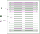
As shown in fig. 1, 5 and 6, a computer case with quick-release side plates, includes machine case 1 and heat dissipation side plate 2, machine case 1 is rectangle machine case 1, the left end face of machine case 1 is opened, heat dissipation side plate 2 can be dismantled and set up on the left end face of machine case 1 and be used for sealing the left end face of machine case 1, the outside of heat dissipation side plate 2 from top to bottom level evenly is provided with a plurality of fin 21, evenly sets up a plurality of bar louvres 22 that run through 2 left end faces of heat dissipation side plate and right end face on heat dissipation side plate 2, and bar louvre 22 level sets up on heat dissipation side plate 2 between adjacent horizontal fin 21.
As shown in fig. 3 and 4, as an implementation manner, the case 1 is provided with a fixing strip 3 on one side of the case contacting with the upper side and the lower side of the heat dissipation side plate 2, a clamping groove 31 is formed in the lower surface of the fixing strip 3 located at the top of the case 1, a clamping groove 31 is formed in the upper surface of the solid strip 3 located at the bottom of the case 1, the top and the bottom of the heat dissipation side plate 2 are disposed in the clamping groove 31 and can move back and forth along the clamping groove 31, the rear end of the fixing strip 3 is provided with a limiting strip 32, the limiting strip 32 is used for limiting the limit position of the backward movement of the heat dissipation side plate 2 along the clamping groove 31, the front end surface of the case 1 is horizontally provided with a moving buckle, and the moving buckle is used for limiting the forward movement of the heat dissipation side plate 2 along the clamping groove 31, so that the heat dissipation side plate 2 is fixed in the clamping groove.
In one embodiment, the front end of the slot 31 is provided with a flared lead-in end.
As an implementation manner, a vertical groove is formed in the front end surface of the limiting strip 32, and a flexible pad strip 321 is disposed in the vertical groove.
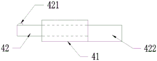
As shown in fig. 7, as an embodiment, the moving latch includes an installation sleeve 41 and a moving plate 42, the moving plate 42 is perpendicular to the heat-dissipating side plate 2, the installation sleeve 41 is disposed on the front end surface of the chassis 1, the moving plate 42 is disposed in the installation sleeve 41 and can move left and right in the installation sleeve 41, and a latch 421 is disposed on the left side of the rear end surface of the moving plate 42.
In one embodiment, a handle 422 is disposed at the right end of the moving plate 42, and the handle 422 is used for limiting the limit distance of the moving plate 42 moving to one end of the buckle 421;
specifically, when the movable buckle is used, the movable plate 42 can be moved left and right by pushing the handle 422, when the heat dissipation side plate 2 is not installed in the slot 31, the path for clamping the heat dissipation side plate 2 with the slot 31 is blocked when the movable plate 42 moves left, and the path for clamping the heat dissipation side plate 2 with the slot 31 is opened when the movable plate 42 moves right; when the heat dissipation side plate 2 is installed in the card slot 31, when the moving plate 42 moves leftward, the buckle 421 will be clamped on the left end surface of the heat dissipation side plate 2, and the moving plate 42 will fix the heat dissipation side plate 2 in the card slot 31, and when the moving plate moves rightward, the buckle 421 will be separated from the heat dissipation side plate 2, and at this time, the heat dissipation side plate 2 can be taken out from the card slot 31.
And (3) mounting a heat dissipation side plate:
the movable plate 42 is pushed by the handle 422 to move rightwards, the top and the bottom of the heat dissipation plate 2 are aligned with the corresponding clamping grooves 31, the top of the heat dissipation plate 2 is clamped into the clamping grooves 31 on the fixing strips 3 at the top of the case, the bottom of the heat dissipation plate 2 is clamped into the clamping grooves 31 on the fixing strips 3 at the bottom of the case, then the heat dissipation side plate 2 is pushed to move backwards along the clamping grooves 31 until the rear end face of the heat dissipation side plate 2 is attached to the flexible pad strips 321, the movable plate 42 is pushed by the handle 422 to move leftwards, the clamping buckles 321 are clamped on the left end face of the heat dissipation side plate 2, and the heat dissipation side plate 2 is limited in the clamping grooves 31 by the movable plate 42 and the limiting strips 32, so that installation is completed;
disassembling the heat dissipation side plate:
the moving plate 42 is shifted to make the fastener 321 separated from the left end face of the heat dissipation side plate 2, the moving plate 42 is pushed by the handle 422 to move rightwards, and then the heat dissipation side plate 2 can be drawn out from the clamping groove 31, so that the disassembly is completed.
The foregoing is illustrative of the best mode of the invention, and details not described herein are within the common general knowledge of a person of ordinary skill in the art. The protection scope of the present invention is subject to the content of the claims, and any equivalent transformation based on the technical teaching of the present invention is also within the protection scope of the present invention.
Claims (6)
1. The utility model provides a computer machine case with quick detach curb plate, a serial communication port, including quick-witted case (1) and heat dissipation curb plate (2), machine case (1) be rectangle quick-witted case (1), the left end face of machine case (1) opens, heat dissipation curb plate (2) can be dismantled and set up on the left end face of machine case (1) and be used for the left end face of closed machine case (1), the outside of heat dissipation curb plate (2) from top to bottom level evenly is provided with a plurality of fin (21), evenly sets up a plurality of bar louvres (22) that run through heat dissipation curb plate (2) left end face and right-hand member face on heat dissipation curb plate (2) between adjacent horizontal fin (21), bar louvre (22) level sets up on heat dissipation curb plate (2).
2. The computer case with the quick-release side plate according to claim 1, wherein the case (1) is provided with a fixing strip (3) on one side in contact with the upper side and the lower side of the heat dissipation side plate (2), a clamping groove (31) is formed in the lower surface of the fixing strip (3) at the top of the case (1), a clamping groove (31) is formed in the upper surface of the fixing strip (3) at the bottom of the case (1), the top and the bottom of the heat dissipation side plate (2) are arranged in the clamping groove (31) and can move back and forth along the clamping groove (31), a limiting strip (32) is arranged at the rear end of the fixing strip (3), the limiting strip (32) is used for limiting the limit position of the backward movement of the heat dissipation side plate (2) along the clamping groove (31), a moving buckle is horizontally arranged on the front end surface of the case (1), and the moving buckle is used for limiting the forward movement of the heat dissipation side plate (2) along the clamping groove (31), so that the heat dissipation side plate (2) is fixed in the clamping groove.
3. The computer case with quick-release side plates according to claim 2, wherein the front end of the slot (31) is provided with a flared lead-in end.
4. The computer case with quick-release side plates as claimed in claim 2, wherein a vertical groove is formed on the front end surface of the limiting strip (32), and a flexible pad strip (321) is arranged in the vertical groove.
5. The computer case with the quick-release side plate as claimed in claim 2, wherein the moving buckle comprises an installation sleeve (41) and a moving plate (42), the moving plate (42) is perpendicular to the heat-dissipation side plate (2), the installation sleeve (41) is disposed on the front end surface of the computer case (1), the moving plate (42) is disposed in the installation sleeve (41) and can move left and right in the installation sleeve (41), and a buckle (421) is disposed on the left side of the rear end surface of the moving plate (42).
6. The computer case with the quick-release side plate as claimed in claim 5, wherein a handle (422) is provided at the right end of the moving plate (42), and the handle (422) is used for limiting the limit distance of the moving plate (42) moving to one end of the buckle (421).
Priority Applications (1)
| Application Number | Priority Date | Filing Date | Title |
|---|---|---|---|
| CN202222903596.9U CN218675932U (en) | 2022-11-02 | 2022-11-02 | Computer machine case with quick detach curb plate |
Applications Claiming Priority (1)
| Application Number | Priority Date | Filing Date | Title |
|---|---|---|---|
| CN202222903596.9U CN218675932U (en) | 2022-11-02 | 2022-11-02 | Computer machine case with quick detach curb plate |
Publications (1)
| Publication Number | Publication Date |
|---|---|
| CN218675932U true CN218675932U (en) | 2023-03-21 |
Family
ID=85568031
Family Applications (1)
| Application Number | Title | Priority Date | Filing Date |
|---|---|---|---|
| CN202222903596.9U Active CN218675932U (en) | 2022-11-02 | 2022-11-02 | Computer machine case with quick detach curb plate |
Country Status (1)
| Country | Link |
|---|---|
| CN (1) | CN218675932U (en) |
-
2022
- 2022-11-02 CN CN202222903596.9U patent/CN218675932U/en active Active
Similar Documents
| Publication | Publication Date | Title |
|---|---|---|
| US20110090643A1 (en) | Computer system | |
| US20120212906A1 (en) | Air duct and electronic device having the same | |
| CN115562448B (en) | Liquid cooling device and server | |
| CN219660270U (en) | Electronic component radiating assembly | |
| CN218675932U (en) | Computer machine case with quick detach curb plate | |
| CN107515657A (en) | A kind of liquid-cooled suit business device containing preposition liquid-cooled air-cooling apparatus | |
| CN211375548U (en) | Water-cooling heat dissipation server based on VPX framework | |
| CN103677149A (en) | Fan fixing device | |
| CN211349203U (en) | Case with high heat dissipation performance | |
| CN209962188U (en) | High-efficient heat dissipation mainframe box | |
| CN211180752U (en) | Special computer cooling system for block chain | |
| CN110888506B (en) | Multimedia dual-core industrial control mainboard | |
| CN205302156U (en) | Easy radiating main chassis exterior | |
| CN218767682U (en) | Display driving main board with ventilation and heat dissipation structure | |
| CN217788028U (en) | Hard disk cartridge capable of realizing high-efficiency heat dissipation | |
| CN211878523U (en) | Easy radiating main frame | |
| CN220731180U (en) | Hard disk box and mobile hard disk | |
| CN214963372U (en) | Table with computer main case | |
| CN210895311U (en) | Computer network equipment box that heat dissipation function is good | |
| CN221009851U (en) | Plug-in frame type uninterrupted power supply | |
| CN220305743U (en) | Radiator maintenance door structure and reinforced computer | |
| CN212992869U (en) | Down-pressing type heat dissipation piece and fan drive control heat dissipation device | |
| CN214623579U (en) | High-efficient radiating combination formula computer power structure | |
| CN219456835U (en) | Embedded box-type computer without fan | |
| CN217506475U (en) | Dustproof notebook computer heat dissipation module |
Legal Events
| Date | Code | Title | Description |
|---|---|---|---|
| GR01 | Patent grant | ||
| GR01 | Patent grant |