CN218661955U - Transfer device of automatic beveling machine for pipeline - Google Patents
Transfer device of automatic beveling machine for pipeline Download PDFInfo
- Publication number
- CN218661955U CN218661955U CN202223329698.0U CN202223329698U CN218661955U CN 218661955 U CN218661955 U CN 218661955U CN 202223329698 U CN202223329698 U CN 202223329698U CN 218661955 U CN218661955 U CN 218661955U
- Authority
- CN
- China
- Prior art keywords
- fixed
- beveling machine
- transfer device
- jib
- automatic beveling
- Prior art date
- Legal status (The legal status is an assumption and is not a legal conclusion. Google has not performed a legal analysis and makes no representation as to the accuracy of the status listed.)
- Active
Links
Images


Landscapes
- Jib Cranes (AREA)
Abstract
The utility model discloses a transfer device of automatic beveling machine of pipeline relates to the supplementary installation technical field of automatic beveling machine. Including fixed station, battery and electric block, the bottom both sides of fixed station all are fixed with the riser, and the bottom mounting of riser has the backup pad, is provided with moving mechanism between the backup pad, and moving mechanism's top is provided with elevating system, and the top swing joint of fixed station has the jib, and electric block is fixed mutually with the top of jib, and the bottom of jib is provided with slewing mechanism. Preferably, a scissors lifter is fixed on one side of the top end of the fixed table, and a standing platform is fixed on the top end of the scissors lifter. The utility model discloses be provided with moving mechanism and elevating system to with the jib integration on the fixed station, realize the removal of device and jib through the universal wheel, realize that the device is fixed through mutually supporting of moving mechanism and elevating system, stability between the device and the ground when having increased the installation, thereby security when having improved the installation.
Description
Technical Field
The utility model relates to an automatic beveling machine auxiliary erection technical field specifically is a transfer device of automatic beveling machine of pipeline.
Background
The pipeline beveling machine is a special tool for chamfering and beveling the front end face of a pipeline or a flat plate in welding.
Because the beveling machine is heavy, in order to reduce labor intensity, in the prior art, the beveling machine is transferred to one side of a pipeline and is installed with the pipeline, the process generally comprises the steps of placing a hoisting frame on one side of the beveling machine, hoisting the beveling machine through the hoisting frame, a hoisting rod fixed on the hoisting frame and a manual hoist hook connected with the hoisting rod, then pushing the beveling machine and pulling a pull rope of the manual hoist by workers until the beveling machine is aligned with the pipeline, and then installing. The prior art has the following defects: 1. the hoisting frame and the suspender are inconvenient to move, and the stability of the hoisting frame is poor when the beveling machine is transported, so that the safety is poor during installation; 2. the suspender is generally fixed, so that the beveling machine needs to be manually pushed to be in butt joint with the pipeline, the labor intensity is increased, and the working efficiency is reduced.
SUMMERY OF THE UTILITY MODEL
An object of the utility model is to provide a transfer device of automatic beveling machine of pipeline to solve the problem that proposes among the above-mentioned background art.
In order to achieve the above object, the utility model provides a following technical scheme: the utility model provides a transfer device of automatic beveling machine of pipeline, includes fixed station, battery and electric block, the bottom both sides of fixed station all are fixed with the riser, and the bottom mounting of riser has the backup pad, is provided with moving mechanism between the backup pad, and moving mechanism's top is provided with elevating system, and the top swing joint of fixed station has the jib, and electric block is fixed mutually with the jib, and the bottom of jib is provided with slewing mechanism.
Preferably, a scissors lifter is fixed on one side of the top end of the fixed table, and a standing platform is fixed on the top end of the scissors lifter.
Preferably, the moving mechanism comprises a lifting plate movably arranged between two vertical plates, the bottom end of the fixed platform is connected with a socket column in a rolling mode, a plurality of universal wheels are fixed at the bottom end of the lifting plate, a plurality of limiting shafts are fixed at the bottom end of the fixed platform and movably connected with the lifting plate in an inserting mode, a threaded rod is fixed at the top end of the lifting plate, and the threaded rod is matched with a threaded hole formed in the bottom of the socket column.
Preferably, the lifting mechanism comprises a first bevel gear fixed with the socket column body and a rotating shaft in rolling connection with a vertical plate on one side, a second bevel gear is fixed at the end of the rotating shaft, the first bevel gear is meshed with the second bevel gear, and a rotating wheel is fixed at the end of the rotating shaft extending out of the vertical plate.
Preferably, the rotating mechanism comprises two connecting plates fixed to the bottom end of the fixed table, a worm is connected between the two connecting plates in a rolling mode, a worm wheel is fixed to the bottom end of the hanging rod and meshed with the worm, a motor is fixed to the side face of each connecting plate, and the output end of the motor is fixed to the end portion of the worm.
Preferably, the body of rod of jib is swing joint has the annular piece, and annular piece bottom mounting has a plurality of bracing pieces, and the bottom of bracing piece is fixed mutually with the top of fixed station.
Compared with the prior art, the beneficial effects of the utility model are that:
the transfer device of the automatic beveling machine for the pipeline is provided with the moving mechanism and the lifting mechanism, the suspender is integrated on the fixed platform, the movement of the device and the suspender is realized through the universal wheel, the fixation of the device is realized through the mutual matching of the moving mechanism and the lifting mechanism, the stability between the device and the ground during installation is increased, and the safety during installation is improved;
in addition, the rotation of the suspender is realized through the arrangement of the rotating mechanism, and the rotation of the electric hoist and the beveling machine connected to the hook of the electric hoist is further realized, so that the butt joint installation between the beveling machine and the pipeline is facilitated, the labor intensity is reduced, and the working efficiency is improved.
Drawings
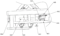
Fig. 1 is a schematic view of the overall mechanism of the present invention;
fig. 2 is a detailed view of the moving mechanism and the lifting mechanism of the present invention;
fig. 3 is a detailed view of the rotating mechanism of the present invention.
In the figure: 1. a fixed table; 2. a vertical plate; 3. a support plate; 4. a moving mechanism; 401. a lifting plate; 402. a limiting shaft; 403. a universal wheel; 404. a threaded rod; 405. a socket post; 5. a lifting mechanism; 501. a rotating shaft; 502. a first bevel gear; 503. a second bevel gear; 504. a rotating wheel; 6. a boom; 7. a rotating mechanism; 701. a worm; 702. a worm gear; 703. a motor; 801. a ring block; 802. a support bar; 9. an electric hoist; 10. a scissor lift; 11. a standing platform; 12. and (4) a storage battery.
Detailed Description
The technical solutions in the embodiments of the present invention will be described clearly and completely with reference to the accompanying drawings in the embodiments of the present invention, and it is obvious that the described embodiments are only some embodiments of the present invention, not all embodiments. Based on the embodiments in the present invention, all other embodiments obtained by a person skilled in the art without creative efforts all belong to the protection scope of the present invention.
It should be noted that, in the description of the present invention, the terms "upper", "lower", "front", "rear", "left", "right", "vertical", "horizontal", "top", "bottom", "inner", "outer", etc. indicate the orientation or positional relationship based on the orientation or positional relationship shown in the drawings, which is only for the convenience of description and simplification of the description, and do not indicate or imply that the device or element referred to must have a specific orientation, be constructed and operated in a specific orientation, and thus, should not be construed as limiting the present invention.
Further, it will be appreciated that the dimensions of the various elements shown in the figures are not drawn to scale, for ease of description, and that the thickness or width of some layers may be exaggerated relative to other layers, for example.
It should be noted that like reference numerals and letters refer to like items in the following figures, and thus, once an item is defined or illustrated in one figure, it will not need to be further discussed or illustrated in detail in the description of the following figure.
The device can realize hoisting the beveling machine, then carries out the regulation of height and position with the beveling machine, makes the height and the position of its height and position adaptation pipeline, then is connected with the pipeline under workman's assistance to the realization carries out the groove to the pipeline.
As shown in fig. 1-3, the utility model provides a technical solution: the utility model provides a transfer device of automatic beveling machine of pipeline, including fixed station 1, battery 12 and electric block 9, still be provided with the controller in addition, electric block 9 can carry out wireless connection with the controller, this be prior art, concrete connection principle and electric block 9's theory of operation no longer gives unnecessary details in this embodiment, all be fixed with riser 2 in the bottom both sides of fixed station 1, and the bottom mounting of riser 2 has backup pad 3, when transporting the installation to the beveling machine, backup pad 3 contacts for ground, thereby this transfer device's stability has been improved, be provided with moving mechanism 4 between backup pad 3, be provided with elevating system 5 at moving mechanism 4's top, top swing joint at fixed station 1 has jib 6, it can know, electric block 9 is fixed mutually with jib 6's top, be provided with slewing mechanism 7 in jib 6's bottom.
For realizing this transfer device and the integration of platform 11 of standing, and conveniently carry out altitude mixture control to platform 11 of standing, in this embodiment, as shown in fig. 1, top one side at fixed station 1 is fixed with scissors lift 10, and the top of scissors lift 10 is fixed with platform 11 of standing, carry out altitude mixture control through controller control scissors lift 10, highly adapt to until its height and pipeline are placed, the workman stands on platform 11 of standing, can install the beveling machine that hangs up through electric block 9 and the pipeline of treating the groove, and the later stage is operated the beveling machine.
In order to facilitate the movement of the device, as shown in fig. 1 and fig. 2, the moving mechanism 4 includes a lifting plate 401 movably disposed between two vertical plates 2, a socket column 405 is connected to the bottom end of the fixed platform 1 in a rolling manner, universal wheels 403 are fixed to four corners of the bottom end of the lifting plate 401, the universal wheels 403 have braking performance, four limit shafts 402 are fixed to the bottom end of the fixed platform 1, it can be known that the limit shafts 402 are movably inserted into the lifting plate 401, limit blocks are fixed to the bottom ends of the limit shafts 402, the setting of the limit blocks prevents the lifting plate 401 from being separated from the limit shafts 402, a threaded rod 404 is fixed to the top end of the lifting plate 401, and it is required to know that the threaded rod 404 is matched with a threaded hole formed in the bottom of the socket column 405.
In order to realize the lifting of the moving mechanism 4 and the movement of the device, as shown in fig. 2, the lifting mechanism 5 comprises a first bevel gear 502 fixed to the body of the socket column 405 and a rotating shaft 501 connected with the vertical plate 2 in a rolling manner, a second bevel gear 503 is fixed to the end of the rotating shaft 501, the first bevel gear 502 is engaged with the second bevel gear 503, and a rotating wheel 504 is fixed to the end of the rotating shaft 501 extending out of the vertical plate 2.
Specifically, during the use, promote beveling machine and pipeline through universal wheel 403 with the device and place the position, then rotate runner 504, runner 504 drives pivot 501 when rotating and rotates, pivot 501 drives second bevel gear 503 when rotating and rotates, because of first bevel gear 502 and second bevel gear 503 mesh mutually, thereby realize bearing and inserting the rotation of post 405, under the limiting displacement of spacing axle 402, the rotation of socket and spigot post 405 drives threaded rod 404 and lifter plate 401 rebound, until universal wheel 403 breaks away from ground and backup pad 3 supports with ground completely and presses, thereby realized fixing the device.
In order to realize the 360-degree rotation of the suspension rod 6, thereby facilitating the hoisting of the beveling machine and the installation between the beveling machine and the pipeline, as shown in fig. 3, the rotating mechanism 7 comprises two connecting plates fixed with the bottom end of the fixed table 1, a worm 701 is connected between the two connecting plates in a rolling manner, a worm wheel 702 is fixed at the bottom end of the suspension rod 6, the worm wheel 702 is meshed with the worm 701, a motor 703 is fixed on the side surface of the connecting plate, and the output end of the motor 703 is fixed with the end part of the worm 701.
Specifically, after carrying out position to the device and injecing and stabilizing, the staff starts through controller control motor 703, motor 703 drives worm 701 when rotating and rotates, because worm 701 and worm wheel 702 mesh mutually, thereby realize jib 6's rotation, electric block 9 on the jib 6 is located the top of beveling machine, stay cord and the couple through controller control electric block 9 descend this moment, the workman is connected couple and beveling machine, and is same, transport the position of pipeline through the controller with the beveling machine, the workman installs the beveling machine in the pipeline of treating processing, after processing is accomplished, place subaerial through controller control jib 6 and electric block 9 the beveling machine that will disassemble.
In order to ensure the stability of the rotation of the suspension rod 6, an annular block 801 is movably connected to the rod body of the suspension rod 6, specifically, a bearing mounting hole is formed in the middle of the annular block 801, a bearing is fixed in the bearing mounting hole, the rod body of the suspension rod 6 is fixed to the inner wall of the inner ring of the bearing, a plurality of support rods 802 are annularly fixed to the bottom end of the annular block 801, and it can be understood that the bottom ends of the support rods 802 are fixed to the top end of the fixed table 1.
Although embodiments of the present invention have been shown and described, it will be appreciated by those skilled in the art that changes, modifications, substitutions and alterations can be made in these embodiments without departing from the principles and spirit of the invention, the scope of which is defined in the appended claims and their equivalents.
Claims (6)
1. The utility model provides a transfer device of automatic beveling machine of pipeline, includes fixed station (1), battery (12) and electric block (9), its characterized in that: the lifting mechanism is characterized in that vertical plates (2) are fixed on two sides of the bottom end of the fixed platform (1), supporting plates (3) are fixed on the bottom ends of the vertical plates (2), a moving mechanism (4) is arranged between the supporting plates (3), a lifting mechanism (5) is arranged at the top of the moving mechanism (4), a hanging rod (6) is movably connected to the top end of the fixed platform (1), an electric hoist (9) is fixed with the hanging rod (6), and a rotating mechanism (7) is arranged at the bottom of the hanging rod (6).
2. The transfer device of the automatic beveling machine for pipes according to claim 1, wherein: a scissors lifter (10) is fixed on one side of the top end of the fixed table (1), and a standing platform (11) is fixed on the top end of the scissors lifter (10).
3. The transfer device of the automatic beveling machine for pipes according to claim 1, wherein: the movable mechanism (4) comprises a lifting plate (401) movably arranged between two vertical plates (2), the bottom end of a fixed table (1) is connected with a socket column (405) in a rolling mode, a plurality of universal wheels (403) are fixed to the bottom end of the lifting plate (401), a plurality of limiting shafts (402) are fixed to the bottom end of the fixed table (1), the limiting shafts (402) are movably connected with the lifting plate (401) in an inserting mode, a threaded rod (404) is fixed to the top end of the lifting plate (401), and the threaded rod (404) is matched with a threaded hole formed in the bottom of the socket column (405).
4. The transfer device of the automatic beveling machine for pipes according to claim 1, wherein: the lifting mechanism (5) comprises a first bevel gear (502) fixed with the body of the socket column (405) and a rotating shaft (501) in rolling connection with a vertical plate (2) on one side, a second bevel gear (503) is fixed at the end of the rotating shaft (501), the first bevel gear (502) is meshed with the second bevel gear (503), and a rotating wheel (504) is fixed at the end of the rotating shaft (501) extending out of the vertical plate (2).
5. The transfer device of the automatic beveling machine for pipes according to claim 1, wherein: the rotating mechanism (7) comprises two connecting plates fixed to the bottom end of the fixed table (1), a worm (701) is connected between the two connecting plates in a rolling mode, a worm wheel (702) is fixed to the bottom end of the hanging rod (6), the worm wheel (702) is meshed with the worm (701), a motor (703) is fixed to the side face of each connecting plate, and the output end of the motor (703) is fixed to the end portion of the worm (701).
6. The transfer device of the automatic beveling machine for pipes according to claim 1, wherein: the utility model discloses a suspension pole, including jib (6), the body of rod is swing joint has annular piece (801) on the body of rod of jib (6), and annular piece (801) bottom mounting has a plurality of bracing pieces (802), and the bottom of bracing piece (802) is fixed mutually with the top of fixed station (1).
Priority Applications (1)
| Application Number | Priority Date | Filing Date | Title |
|---|---|---|---|
| CN202223329698.0U CN218661955U (en) | 2022-12-13 | 2022-12-13 | Transfer device of automatic beveling machine for pipeline |
Applications Claiming Priority (1)
| Application Number | Priority Date | Filing Date | Title |
|---|---|---|---|
| CN202223329698.0U CN218661955U (en) | 2022-12-13 | 2022-12-13 | Transfer device of automatic beveling machine for pipeline |
Publications (1)
| Publication Number | Publication Date |
|---|---|
| CN218661955U true CN218661955U (en) | 2023-03-21 |
Family
ID=85549925
Family Applications (1)
| Application Number | Title | Priority Date | Filing Date |
|---|---|---|---|
| CN202223329698.0U Active CN218661955U (en) | 2022-12-13 | 2022-12-13 | Transfer device of automatic beveling machine for pipeline |
Country Status (1)
| Country | Link |
|---|---|
| CN (1) | CN218661955U (en) |
-
2022
- 2022-12-13 CN CN202223329698.0U patent/CN218661955U/en active Active
Similar Documents
| Publication | Publication Date | Title |
|---|---|---|
| CN201474315U (en) | Moveable hoisting brick clamp | |
| CN111350358A (en) | Multifunctional cement plate erecting machine with good safety protection | |
| CN218661955U (en) | Transfer device of automatic beveling machine for pipeline | |
| CN214828751U (en) | Auxiliary supporting platform for hoisting steel structure truss | |
| CN112477734B (en) | Construction pipeline moving device | |
| CN213865142U (en) | Movable building construction material hoisting device | |
| CN112357821B (en) | PCCP spiral welding and water pressure inspection automatic assembly line and application method thereof | |
| CN212828597U (en) | Stone material conveyor | |
| CN211004274U (en) | Municipal works hoisting equipment | |
| CN210505314U (en) | Hoisting device for civil air defense equipment installation | |
| CN111977507A (en) | High quick tubular pile transfer device of security | |
| CN216889933U (en) | Power equipment reforms transform and props device with frame | |
| CN216190608U (en) | Equipment transportation trailer with limit structure | |
| CN217515172U (en) | Novel pipeline transportation device | |
| CN219826079U (en) | Attached scaffold for building construction | |
| CN218491322U (en) | Motor overhead hoist | |
| CN210065024U (en) | Hoisting device for mechanical engineering | |
| CN209833593U (en) | AGV dolly battery maintenance car | |
| CN219341610U (en) | Pipeline lifting device | |
| CN220550870U (en) | Concrete pouring device | |
| CN204137025U (en) | Interior panel transport trolley | |
| CN216235739U (en) | A hoisting accessory for civil engineering main equipment transportation usefulness | |
| CN210563478U (en) | Lifting and positioning device for light energy-saving wall board of ultra-high wall | |
| CN217437072U (en) | Universal moving platform for manual operation of power-assisted arm manipulator | |
| CN220537360U (en) | Assembled piping lane hoist device |
Legal Events
| Date | Code | Title | Description |
|---|---|---|---|
| GR01 | Patent grant | ||
| GR01 | Patent grant |