CN218648565U - Overcurrent protection circuit of optical module and optical module - Google Patents
Overcurrent protection circuit of optical module and optical module Download PDFInfo
- Publication number
- CN218648565U CN218648565U CN202222870615.2U CN202222870615U CN218648565U CN 218648565 U CN218648565 U CN 218648565U CN 202222870615 U CN202222870615 U CN 202222870615U CN 218648565 U CN218648565 U CN 218648565U
- Authority
- CN
- China
- Prior art keywords
- power supply
- optical module
- comparator
- current sampling
- current
- Prior art date
- Legal status (The legal status is an assumption and is not a legal conclusion. Google has not performed a legal analysis and makes no representation as to the accuracy of the status listed.)
- Active
Links
Images

Landscapes
- Emergency Protection Circuit Devices (AREA)
Abstract
The utility model discloses an overcurrent protection circuit of an optical module and the optical module, wherein the overcurrent protection circuit of the optical module comprises a main board power supply, a current sampling circuit, a power switch, a load and a comparator; the input end of the current sampling circuit is connected with the output end of the main board power supply; the current sampling circuit is used for detecting the power supply current of the mainboard power supply; the power switch is connected with the output end of the current sampling circuit; the load is connected with the power switch; the first input end of the comparator is connected with the output end of the current sampling circuit, the output end of the comparator is connected with the power switch, and the comparator is used for controlling the working state of the power switch according to the power supply current; according to the utility model provides a technical scheme can protect the inside components and parts of optical module, avoids the emergence of potential safety hazard.
Description
Technical Field
The utility model relates to an electronic circuit field, in particular to overcurrent protection circuit and optical module of optical module.
Background
As the transmission rate of the optical module increases, the power consumption of the optical module also becomes larger and larger, so that the safety circuit design part of the optical module becomes one of the problems to be solved urgently. At present, the optical module only has a design of preventing current surge at a power input part, and does not have a design of managing and controlling the large current abnormal condition of the optical module; when the current flowing through the optical module is too large, components inside the optical module are easily damaged, so that certain potential safety hazards exist when the optical module is used.
SUMMERY OF THE UTILITY MODEL
The utility model discloses aim at solving one of the technical problem that exists among the prior art at least. Therefore, the utility model provides an overcurrent protection circuit and optical module of optical module can protect the inside components and parts of optical module, avoids the emergence of potential safety hazard.
The embodiment of the first aspect of the utility model provides an overcurrent protection circuit of an optical module, which comprises a main board power supply, a current sampling circuit, a power switch, a load and a comparator; the input end of the current sampling circuit is connected with the output end of the main board power supply; the current sampling circuit is used for detecting the power supply current of the mainboard power supply; the power switch is connected with the output end of the current sampling circuit; the load is connected with the power switch; the first input end of the comparator is connected with the output end of the current sampling circuit, the output end of the comparator is connected with the power switch, and the comparator is used for controlling the working state of the power switch according to the power supply current.
According to the utility model discloses the overcurrent protection circuit of optical module that provides has following beneficial effect at least: the main board power supply is used for outputting power supply current, and the power supply current supplies power to a load through the current sampling circuit and the power switch; the current sampling circuit is used for detecting the power supply current, and the comparator can control the working state of the power switch according to the magnitude of the power supply current so as to control the on-off of a path for supplying power to a load by the main board power supply; under the condition that the supply current output by the main board power supply is overlarge, the comparator can output a low level, so that the power switch is turned off, a path for supplying power to a load by the main board power supply is cut off, components in the optical module are protected, and potential safety hazards are avoided.
According to the utility model discloses a some embodiments still include the DAC module, the DAC module is used for the output voltage threshold value, the DAC module with the second input of comparator is connected, the comparator is used for comparing sampling voltage after the supply current conversion with the voltage threshold value works as sampling voltage is greater than during the voltage threshold value, turn-offs switch.
According to the utility model discloses a some embodiments, the electric current sampling circuit includes the electric current sampling chip, the input of electric current sampling chip with the output of mainboard power is connected, the output of electric current sampling chip respectively with switch with the first input of comparator is connected.
According to the utility model discloses a some embodiments still include first resistance, the one end of first resistance respectively with the output of current sampling chip with the first input of comparator is connected, the other end ground connection of first resistance.
According to some embodiments of the present invention, the capacitor further comprises a first capacitor connected in parallel with the first resistor.
According to the utility model discloses a some embodiments still include the second resistance, the one end of second resistance respectively with the mainboard power with the input of current sampling chip is connected, the other end of second resistance respectively with the output of current sampling chip with switch connects.
According to the utility model discloses a some embodiments still include the second electric capacity, the one end of second electric capacity respectively with the output of current sampling chip with switch connects, the other end ground connection of second electric capacity.
According to the utility model discloses a some embodiments still include third electric capacity and fourth electric capacity, the one end of third electric capacity respectively with switch with the load is connected, the other end ground connection of third electric capacity, the fourth electric capacity with third electric capacity is parallelly connected.
According to some embodiments of the utility model, still include the VCC power, the VCC power with the power end of comparator is connected.
An embodiment of the second aspect of the present invention provides an optical module, including the overcurrent protection circuit of the optical module as described in the embodiment of the first aspect.
According to the utility model provides an optical module has following beneficial effect at least: the main board power supply is used for outputting power supply current, and the power supply current supplies power to a load through the current sampling circuit and the power switch; the current sampling circuit is used for detecting the power supply current, and the comparator can control the working state of the power switch according to the magnitude of the power supply current so as to control the on-off of a path for supplying power to a load by the main board power supply; under the condition that the supply current output by the main board power supply is overlarge, the comparator can output a low level, so that the power switch is turned off, a path for supplying power to a load by the main board power supply is cut off, components in the optical module are protected, and potential safety hazards are avoided.
Drawings
Additional aspects and advantages of the present invention will become apparent and readily appreciated from the following description of the embodiments, taken in conjunction with the accompanying drawings of which:
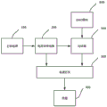
fig. 1 is a schematic structural diagram of an overcurrent protection circuit of an optical module according to an embodiment of the present invention;
fig. 2 is a schematic circuit diagram of an overcurrent protection circuit of an optical module according to some embodiments of the present invention.
Detailed Description
Reference will now be made in detail to the embodiments of the present invention, examples of which are illustrated in the accompanying drawings, wherein like reference numerals refer to the same or similar elements or elements having the same or similar functions throughout. The embodiments described below with reference to the drawings are exemplary only for the purpose of explaining the present invention, and should not be construed as limiting the present invention.
In the description of the present invention, it should be understood that the orientation or positional relationship indicated with respect to the orientation description, such as up, down, front, rear, left, right, etc., is based on the orientation or positional relationship shown in the drawings, and is only for convenience of description and simplification of description, and does not indicate or imply that the device or element referred to must have a specific orientation, be constructed and operated in a specific orientation, and thus, should not be construed as limiting the present invention.
In the description of the present invention, a plurality of meanings are one or more, a plurality of meanings are two or more, and the terms greater than, smaller than, exceeding, etc. are understood as excluding the number, and the terms greater than, lower than, within, etc. are understood as including the number. If there is a description of first and second for the purpose of distinguishing technical features only, this is not to be understood as indicating or implying a relative importance or implicitly indicating the number of technical features indicated or implicitly indicating the precedence of technical features indicated.
In the description of the present invention, unless there is an explicit limitation, the words such as setting, installation, connection, etc. should be understood in a broad sense, and those skilled in the art can reasonably determine the specific meanings of the above words in combination with the specific contents of the technical solution.
As shown in fig. 1 to fig. 2, an embodiment of the first aspect of the present invention provides an overcurrent protection circuit for an optical module, including a main board power supply 100, a current sampling circuit 200, a power switch 300, a load 400, and a comparator 500; the input end of the current sampling circuit 200 is connected with the output end of the main board power supply 100; the current sampling circuit 200 is used for detecting the power supply current of the main board power supply 100; the power switch 300 is connected with the output end of the current sampling circuit 200; the load 400 is connected to the power switch 300; a first input terminal of the comparator 500 is connected to the output terminal of the current sampling circuit 200, an output terminal of the comparator 500 is connected to the power switch 300, and the comparator 500 is configured to control the operating state of the power switch 300 according to the supply current.
According to the embodiment of the present invention, the main board power supply 100 is used for outputting a power supply current, and the power supply current is supplied to the load 400 through the current sampling circuit 200 and the power switch 300; the current sampling circuit 200 is configured to detect a supply current, and the comparator 500 can control a working state of the power switch 300 according to the magnitude of the supply current, so as to control on/off of a path through which the main board power supply 100 supplies power to the load 400; under the condition that the supply current output by the main board power supply 100 is too large, the comparator 500 can output a low level, so that the power switch 300 is turned off, a path for supplying power to the load 400 by the main board power supply 100 is cut off, components inside the optical module are protected, and potential safety hazards are avoided.
It should be noted that, after the main board power supply 100 outputs the supply current, the current sampling circuit 200 can perform corresponding conversion processing on the detected supply current and then output the converted supply current to the comparator 500 for judgment, and the comparator 500 can control the operating state of the power switch 300 according to the magnitude of the supply current; when the power supply current is in the normal range value, the comparator 500 can output a high level to turn on the power switch 300, so that the optical module works normally; when the accessed power supply current exceeds the normal range value, the comparator 500 can output a low level to turn off the power switch 300, and the optical module stops working, so that components inside the optical module are prevented from being damaged by a large current; that is, in the case of a large current, the comparator 500 can cut off the path through which the motherboard power supply 100 supplies power to the load 400, and can further protect the load 400 and avoid the occurrence of a potential safety hazard.
As shown in fig. 1, according to some embodiments of the present invention, the power switch further comprises a DAC module 600, the DAC module 600 is used for outputting a voltage threshold, the DAC module 600 is connected to the second input terminal of the comparator 500, the comparator 500 is used for comparing the converted sampling voltage of the supply current with the voltage threshold, and when the sampling voltage is greater than the voltage threshold, the power switch 300 is turned off.
It should be noted that, the operator may set a specific voltage threshold value in the DAC module 600 according to the bearing capacity of the load 400, and is not limited in this embodiment. After setting the specific voltage threshold, the DAC module 600 can output the voltage threshold to the comparator 500, so that the comparator 500 can compare the sampling voltage accessed by the first input terminal with the voltage threshold of the DAC module 600 accessed by the second input terminal. When the sampling voltage is greater than the voltage threshold, indicating that an overcurrent phenomenon occurs, the comparator 500 outputs a low level, and the power switch 300 is turned off to cut off a path between the motherboard power supply 100 and the load 400, and stop supplying power to the load 400; when the sampling voltage is smaller than the voltage threshold value, which indicates that the current flowing through the current sampling circuit 200 is within the normal range, the comparator 500 outputs a high level, and the power switch 300 is turned on to connect the main board power supply 100 and the load 400, so that the optical module works normally. The overcurrent protection circuit of the embodiment can protect components inside the optical module under the condition of overlarge current, and avoids potential safety hazards.
As shown in fig. 2, according to some embodiments of the present invention, the current sampling circuit 200 includes a current sampling chip U1, an input terminal of the current sampling chip U1 is connected to an output terminal of the main board power supply 100, and an output terminal of the current sampling chip U1 is connected to the first input terminals of the power switch 300 and the comparator 500, respectively.
It should be noted that the current sampling circuit 200 includes a current sampling chip U1, and when the supply current output by the motherboard power supply 100 is too large, that is, the current flowing through the current sampling chip U1 is too large, the current sampling chip U1 outputs a corresponding current signal, which is convenient for the comparator 500 to determine.
As shown in fig. 2, according to some embodiments of the present invention, the power supply further includes a first resistor R1, one end of the first resistor R1 is connected to the output end of the current sampling chip U1 and the first input end of the comparator 500, and the other end of the first resistor R1 is grounded.
It should be noted that the overcurrent protection circuit of the optical module further includes a first resistor R1, the first resistor R1 is respectively connected to the output end of the current sampling chip U1 and the first input end of the comparator 500, and the current sampling chip U1 can convert the detected supply current into a sampling voltage through the first resistor R1 and then transmit the sampling voltage to the first input end of the comparator 500, so that the comparator 500 can compare the sampling voltage accessed by the first input end with the voltage threshold value accessed by the second input end.
As shown in fig. 2, according to some embodiments of the present invention, the capacitor further includes a first capacitor C1, and the first capacitor C1 is connected in parallel with the first resistor R1.
It should be noted that the overcurrent protection circuit of the optical module is further provided with a first capacitor C1, one end of the first capacitor C1 is connected with the first resistor R1, and the other end of the first capacitor C1 is connected with the first input end of the comparator 500; the sampling voltage converted by the first resistor R1 is filtered by the first capacitor C1 and then transmitted to the first input terminal of the comparator 500, and the comparator 500 can compare the sampling voltage accessed by the first input terminal with the voltage threshold value accessed by the second input terminal, and control the working state of the power switch 300 according to the comparison result, so as to protect the components inside the optical module from being damaged.
As shown in fig. 2, according to the utility model discloses a some embodiments still include second resistance R2, and second resistance R2's one end is connected with mainboard power supply 100 and current sampling chip U1's input respectively, and second resistance R2's the other end is connected with current sampling chip U1's output and switch 300 respectively.
It should be noted that the overcurrent protection circuit of the optical module is further provided with a second resistor R2, the second resistor R2 is respectively connected to the main board power supply 100 and the current sampling chip U1, and the supply current output by the main board power supply 100 flows through the second resistor R2, so that the current sampling chip U1 can perform current sampling according to the voltage difference between two ends of the second resistor R2.
As shown in fig. 2, according to the present invention, the second capacitor C2 is further included, one end of the second capacitor C2 is connected to the output of the current sampling chip U1 and the power switch 300, and the other end of the second capacitor C2 is grounded.
It should be noted that the overcurrent protection circuit of the optical module is further provided with a second capacitor C2, and the second capacitor C2 is respectively connected with the current sampling chip U1 and the power switch 300, and can play a role of filtering, so that the stable operation of the overcurrent protection circuit of the optical module is ensured.
As shown in fig. 2, according to some embodiments of the present invention, the power supply further includes a third capacitor C3 and a fourth capacitor C4, one end of the third capacitor C3 is connected to the power switch 300 and the load 400, the other end of the third capacitor C3 is grounded, and the fourth capacitor C4 is connected to the third capacitor C3 in parallel.
It should be noted that, the overcurrent protection circuit of the optical module is further provided with a third capacitor C3 and a fourth capacitor C4, and when the power switch 300 is in an open state, the power supply current output by the motherboard power supply 100 can be transmitted to the load 400 through the current sampling circuit 200, the comparator 500, the power switch 300, the third capacitor C3, and the fourth capacitor C4, so as to supply power to the load 400; the third capacitor C3 and the fourth capacitor C4 have a filtering function, so that the load 400 can be ensured to be in a stable working state, and components inside the optical module are further protected.
As shown in fig. 2, according to some embodiments of the present invention, a VCC power supply 700 is further included, and the VCC power supply 700 is connected to the power terminal of the comparator 500.
It should be noted that the overcurrent protection circuit of the optical module is further provided with a VCC power supply 700, and the VCC power supply 700 is connected to a power supply terminal of the comparator 500 and is used for supplying power to the comparator 500, so that the comparator 500 can be always in a normal working state.
An embodiment of the second aspect of the present invention provides an optical module, including an overcurrent protection circuit of an optical module as described in the embodiment of the first aspect.
According to the utility model provides an optical module, including mainboard power 100, current sampling circuit 200, switch 300, load 400 and comparator 500; the input end of the current sampling circuit 200 is connected with the output end of the main board power supply 100; the current sampling circuit 200 is used for detecting the power supply current of the main board power supply 100; the power switch 300 is connected with the output end of the current sampling circuit 200; the load 400 is connected to the power switch 300; a first input terminal of the comparator 500 is connected to the output terminal of the current sampling circuit 200, an output terminal of the comparator 500 is connected to the power switch 300, and the comparator 500 is configured to control the operating state of the power switch 300 according to the supply current.
According to the optical module provided by the present invention, the main board power supply 100 is used for outputting a power supply current, and the power supply current supplies power to the load 400 through the current sampling circuit 200, the comparator 500 and the power switch 300; the current sampling circuit 200 is configured to detect a supply current, and the comparator 500 can control a working state of the power switch 300 according to a magnitude of the supply current, so as to control on/off of a path through which the main board power supply 100 supplies power to the load 400; under the condition that the supply current output by the main board power supply 100 is too large, the comparator 500 can output a low level, so that the power switch 300 is turned off, a path for supplying power to the load 400 by the main board power supply 100 is cut off, components inside the optical module are protected, and potential safety hazards are avoided.
It should be noted that the embodiment of the present invention can implement the over-current protection of the optical module circuit through the hardware structure, and does not relate to the improvement of the method.
The embodiments of the present invention have been described in detail with reference to the accompanying drawings, but the present invention is not limited to the above embodiments, and various changes can be made without departing from the spirit of the present invention within the knowledge scope of those skilled in the art.
Claims (10)
1. An overcurrent protection circuit of an optical module, comprising:
a main board power supply;
the input end of the current sampling circuit is connected with the output end of the mainboard power supply; the current sampling circuit is used for detecting the power supply current of the mainboard power supply;
the power switch is connected with the output end of the current sampling circuit;
a load connected to the power switch;
the first input end of the comparator is connected with the output end of the current sampling circuit, the output end of the comparator is connected with the power switch, and the comparator is used for controlling the working state of the power switch according to the power supply current.
2. The overcurrent protection circuit of the optical module according to claim 1, further comprising a DAC module, wherein the DAC module is configured to output a voltage threshold, the DAC module is connected to a second input terminal of the comparator, the comparator is configured to compare a sampling voltage obtained after the conversion of the supply current with the voltage threshold, and when the sampling voltage is greater than the voltage threshold, the power switch is turned off.
3. The overcurrent protection circuit of the optical module according to claim 2, wherein the current sampling circuit comprises a current sampling chip, an input terminal of the current sampling chip is connected to an output terminal of the motherboard power supply, and an output terminal of the current sampling chip is connected to the power switch and the first input terminal of the comparator respectively.
4. The overcurrent protection circuit of the optical module according to claim 3, further comprising a first resistor, wherein one end of the first resistor is connected to the output terminal of the current sampling chip and the first input terminal of the comparator, respectively, and the other end of the first resistor is grounded.
5. The over-current protection circuit of the light module according to claim 4, further comprising a first capacitor connected in parallel with the first resistor.
6. The overcurrent protection circuit of the optical module according to claim 3, further comprising a second resistor, wherein one end of the second resistor is connected to the motherboard power supply and the input terminal of the current sampling chip, and the other end of the second resistor is connected to the output terminal of the current sampling chip and the power switch.
7. The over-current protection circuit of the optical module according to claim 3, further comprising a second capacitor, wherein one end of the second capacitor is connected to the output terminal of the current sampling chip and the power switch, respectively, and the other end of the second capacitor is grounded.
8. The overcurrent protection circuit of the optical module according to claim 1, further comprising a third capacitor and a fourth capacitor, wherein one end of the third capacitor is connected to the power switch and the load, respectively, the other end of the third capacitor is grounded, and the fourth capacitor is connected in parallel with the third capacitor.
9. The overcurrent protection circuit for the optical module according to claim 1, further comprising a VCC power supply, wherein the VCC power supply is connected to a power supply terminal of the comparator.
10. A light module comprising an overcurrent protection circuit of a light module as claimed in any one of claims 1 to 9.
Priority Applications (1)
| Application Number | Priority Date | Filing Date | Title |
|---|---|---|---|
| CN202222870615.2U CN218648565U (en) | 2022-10-28 | 2022-10-28 | Overcurrent protection circuit of optical module and optical module |
Applications Claiming Priority (1)
| Application Number | Priority Date | Filing Date | Title |
|---|---|---|---|
| CN202222870615.2U CN218648565U (en) | 2022-10-28 | 2022-10-28 | Overcurrent protection circuit of optical module and optical module |
Publications (1)
| Publication Number | Publication Date |
|---|---|
| CN218648565U true CN218648565U (en) | 2023-03-17 |
Family
ID=85494644
Family Applications (1)
| Application Number | Title | Priority Date | Filing Date |
|---|---|---|---|
| CN202222870615.2U Active CN218648565U (en) | 2022-10-28 | 2022-10-28 | Overcurrent protection circuit of optical module and optical module |
Country Status (1)
| Country | Link |
|---|---|
| CN (1) | CN218648565U (en) |
-
2022
- 2022-10-28 CN CN202222870615.2U patent/CN218648565U/en active Active
Similar Documents
| Publication | Publication Date | Title |
|---|---|---|
| US11329477B2 (en) | Direct-current voltage supply circuit | |
| CN110707660A (en) | Load overcurrent protection circuit | |
| CN218648565U (en) | Overcurrent protection circuit of optical module and optical module | |
| CN211239320U (en) | Hot plug control circuit with thermal protection function | |
| US20130155565A1 (en) | Overcurrent protection circuit | |
| CN109193834B (en) | Overvoltage protection device, method and system | |
| US6222716B1 (en) | Power line protection devices and methods for providing overload protection to multiple outputs | |
| US6014299A (en) | Device and method for protecting a CPU from being damaged by an overrating voltage or overrating current | |
| CN214412262U (en) | Protection circuit, circuit board and protection system | |
| CN111834981B (en) | Overcurrent protection circuit and system | |
| CN210111581U (en) | Protective circuit | |
| CN215181880U (en) | USB power supply circuit and USB equipment | |
| CN210609170U (en) | HPLC communication module with overcurrent prevention function in electric energy meter, and electric energy meter | |
| CN210724182U (en) | Load overcurrent protection circuit | |
| CN218068245U (en) | Power supply current detection circuit | |
| CN211764941U (en) | Power battery high-voltage interlocking protection circuit and device | |
| CN214154050U (en) | Battery protection circuit, battery protection board, battery and electronic equipment | |
| CN218415802U (en) | Battery power supply under-voltage protection circuit, device and power supply with under-voltage protection | |
| CN217135150U (en) | Time delay protection control circuit | |
| US11831145B2 (en) | Current sensing protection device for sensing whether current sensing element occurs short phenomenon | |
| CN216672594U (en) | Surge protection circuit, circuit board and electrical apparatus | |
| CN211239313U (en) | Protection circuit and protection system | |
| CN213304964U (en) | Overvoltage protection circuit | |
| CN211209606U (en) | Discharge circuit | |
| CN113315110B (en) | DC power supply circuit |
Legal Events
| Date | Code | Title | Description |
|---|---|---|---|
| GR01 | Patent grant | ||
| GR01 | Patent grant |