CN218619844U - A kind of pipe spreader and its supporting frame - Google Patents
A kind of pipe spreader and its supporting frame Download PDFInfo
- Publication number
- CN218619844U CN218619844U CN202223262991.XU CN202223262991U CN218619844U CN 218619844 U CN218619844 U CN 218619844U CN 202223262991 U CN202223262991 U CN 202223262991U CN 218619844 U CN218619844 U CN 218619844U
- Authority
- CN
- China
- Prior art keywords
- rope
- connecting rod
- support bar
- support
- crank arm
- Prior art date
- Legal status (The legal status is an assumption and is not a legal conclusion. Google has not performed a legal analysis and makes no representation as to the accuracy of the status listed.)
- Expired - Fee Related
Links
- 230000005484 gravity Effects 0.000 claims abstract description 5
- 241000208125 Nicotiana Species 0.000 claims 4
- 235000002637 Nicotiana tabacum Nutrition 0.000 claims 4
- 238000010276 construction Methods 0.000 claims 1
- 210000005069 ears Anatomy 0.000 abstract description 9
- 238000000034 method Methods 0.000 description 3
- 229910000831 Steel Inorganic materials 0.000 description 2
- 238000012986 modification Methods 0.000 description 2
- 230000004048 modification Effects 0.000 description 2
- 239000010959 steel Substances 0.000 description 2
- 230000009286 beneficial effect Effects 0.000 description 1
- 238000010586 diagram Methods 0.000 description 1
- 239000002657 fibrous material Substances 0.000 description 1
- 230000014509 gene expression Effects 0.000 description 1
- 239000002699 waste material Substances 0.000 description 1
Images


Landscapes
- Load-Engaging Elements For Cranes (AREA)
Abstract
本实用新型涉及一种烟斗式吊具及其支撑架,涉及提升工具的技术领域,包括:绳索、卸扣以及支撑架,所述卸扣安装于所述绳索的两端烟斗式吊架的数量为四个,每个待提升车辆轮胎的外侧安装有烟斗式吊架,绳索与烟斗式吊架相连并利用烟斗式吊架将车辆吊起;支撑架包括第一支撑杆、第二支撑杆以及挂耳;第一支撑杆与第二支撑杆构成矩形,挂耳位于第一支撑杆的两端;支撑架位于待提升车辆的正上方且支撑架的中心点与待提升车辆的重心位于同一垂直线上;绳索的末端穿过支撑架对应位置的挂耳,以使支撑架对绳索进行支撑。通过本实用新型提供的吊具可以缓解现有技术中汽车提升存在着操作不便,拆卸困难,使用寿命短的技术问题的技术问题。
The utility model relates to a pipe-type hanger and its supporting frame, and relates to the technical field of lifting tools, including: a rope, a shackle and a supporting frame, and the shackle is installed at both ends of the rope. There are four, and a pipe hanger is installed on the outside of each vehicle tire to be lifted, and the rope is connected with the pipe hanger and the vehicle is hoisted by the pipe hanger; the support frame includes a first support rod, a second support rod and Hanging ears; the first support bar and the second support bar form a rectangle, and the hanging ears are located at both ends of the first support bar; the support frame is located directly above the vehicle to be lifted and the center point of the support frame is at the same vertical as the center of gravity of the vehicle to be lifted On the line; the end of the rope passes through the hanging lug at the corresponding position of the support frame, so that the support frame can support the rope. The hanger provided by the utility model can alleviate the technical problems of inconvenient operation, difficult disassembly and short service life in the prior art of automobile lifting.
Description
技术领域technical field
本实用新型涉及提升装置的技术领域,尤其是涉及一种烟斗式吊具及其支撑架。The utility model relates to the technical field of hoisting devices, in particular to a pipe-type suspender and a supporting frame thereof.
背景技术Background technique
以往车辆吊装工艺为汽车吊带配合撑杠进行吊装,在装船过程中存在以下问题:In the past, the vehicle hoisting process was hoisting with the car sling and the support bar. The following problems existed during the loading process:
1)当车辆吊入船舱定位后,有些车辆在船舱内不允许再次移动,汽车吊带无法从车轮下顺利抽出。1) After the vehicle is hoisted into the cabin for positioning, some vehicles are not allowed to move again in the cabin, and the car sling cannot be pulled out smoothly from under the wheel.
2)汽车吊带是由纤维材料制成易磨损,使用寿命短,而且在受到挤压、摩擦、碰撞时极易发生破损,一旦破损达到一定程度时就会影响到吊装安全,而要报废重新购置时由于汽车吊带的成本较高将造成极大的浪费。2) The car sling is made of fiber material, which is easy to wear, has a short service life, and is easily damaged when it is squeezed, rubbed, or collided. Once the damage reaches a certain level, it will affect the safety of hoisting, and it must be scrapped and repurchased Sometimes it will cause great waste due to the high cost of the car sling.
综上所述,现有技术中,汽车提升存在着操作不便,拆卸困难,使用寿命短的技术问题。In summary, in the prior art, there are technical problems of inconvenient operation, difficult disassembly and short service life in the car lifting.
实用新型内容Utility model content
有鉴于此,本实用新型的目的在于提供一种烟斗式吊具及其支撑架,以缓解现有技术中汽车提升存在着操作不便,拆卸困难,使用寿命短的技术问题。In view of this, the purpose of this utility model is to provide a pipe-type spreader and its supporting frame, so as to alleviate the technical problems of inconvenient operation, difficult disassembly and short service life of automobile lifting in the prior art.
一方面,本实用新型提供了一种烟斗式吊具,包括:绳索以及卸扣,所述卸扣安装于所述绳索的两端,其特征在于,还包括烟斗式吊架;On the one hand, the utility model provides a pipe-type hanger, including: a rope and a shackle, the shackle is installed at both ends of the rope, and is characterized in that it also includes a pipe-type hanger;
所述烟斗式吊架的数量为四个,每个待提升车辆轮胎的外侧安装有所述烟斗式吊架,所述绳索与所述烟斗式吊架相连并利用所述烟斗式吊架将车辆吊起;The number of the pipe hangers is four, and the outside of each vehicle tire to be lifted is equipped with the pipe hangers, and the rope is connected with the pipe hangers and the vehicle is lifted by the pipe hangers. hoist;
所述烟斗式吊架包括连接杆、第三支撑杆、第四支撑杆、第五支撑杆以及曲臂;The pipe hanger includes a connecting rod, a third support rod, a fourth support rod, a fifth support rod and a crank arm;
所述曲臂的数量为两根且位于所述连接杆的两侧,一根曲臂的一端与所述连接杆的一侧固定连接,另一根曲臂的一端与所述连接杆的另一侧固定连接;The quantity of described curved arm is two and is positioned at the both sides of described connecting rod, and one end of one curved arm is fixedly connected with one side of described connecting rod, and one end of another curved arm is connected with the other side of described connecting rod. Fixed connection on one side;
所述第三支撑杆的数量为两根,所述第三支撑杆位于连接杆的两侧且所述第三支撑杆与所述连接杆、所述曲臂构成的平面垂直,所述第三支撑杆与所述曲臂固定连接;The number of the third support rod is two, the third support rod is located on both sides of the connecting rod and the third support rod is perpendicular to the plane formed by the connecting rod and the curved arm, the third support rod The support rod is fixedly connected with the crank arm;
所述第四支撑杆分别与两根所述曲臂固定连接,且与所述连接杆平行放置;The fourth support rods are fixedly connected to the two curved arms respectively, and placed parallel to the connecting rods;
所述第五支撑杆与所述连接杆以及所述第四支撑杆均固定连接;The fifth support rod is fixedly connected to the connecting rod and the fourth support rod;
所述曲臂以及所述连接杆为空心结构,以使所述绳索依次穿过所述曲臂、连接杆以及另一根曲臂;The crank arm and the connecting rod are hollow structures, so that the rope passes through the crank arm, the connecting rod and another crank arm in sequence;
所述连接杆的长度小于待提升车辆轮胎外径。The length of the connecting rod is smaller than the outer diameter of the tire of the vehicle to be lifted.
优选的,所述曲臂与所述第三支撑杆的连接处呈圆角。Preferably, the joint between the crank arm and the third support rod has rounded corners.
优选的,第五支撑杆的顶部所述具有两个通孔,通孔所在的平面与所述第五支撑杆垂直,所述绳索的末端穿过靠近绳索末端的通孔。Preferably, the top of the fifth support rod has two through holes, the plane where the through holes are located is perpendicular to the fifth support rod, and the end of the rope passes through the through hole near the end of the rope.
优选的,所述第三支撑杆与所述曲臂呈一体结构。Preferably, the third support rod and the crank arm are in an integral structure.
优选的,所述曲臂预所述连接杆焊接。Preferably, the crank arm is pre-welded with the connecting rod.
优选的,所述第四支撑杆的两端分别与两根所述曲臂焊接。Preferably, both ends of the fourth support rod are respectively welded to the two curved arms.
优选的,所述第五支撑杆与所述连接杆以及所述第四支撑杆焊接。Preferably, the fifth support rod is welded to the connecting rod and the fourth support rod.
另一方面,本实用新型提供了一种与一种烟斗式吊具适配的一种烟斗式吊具支撑架,包括第一支撑杆、第二支撑杆以及挂耳;On the other hand, the utility model provides a pipe-type spreader support frame adapted to a pipe-type spreader, including a first support rod, a second support rod and hanging lugs;
所述支撑架位于所述待提升车辆的正上方且所述支撑架的中心点与所述待提升车辆的重心位于同一垂直线上;The support frame is located directly above the vehicle to be lifted and the center point of the support frame is on the same vertical line as the center of gravity of the vehicle to be lifted;
所述第一支撑杆与所述第二支撑杆构成矩形,所述挂耳位于所述第一支撑杆的两端;The first support rod and the second support rod form a rectangle, and the hanging ears are located at both ends of the first support rod;
所述绳索的末端穿过所述支撑架对应位置的挂耳,以使支撑架对所述绳索进行支撑。The ends of the ropes pass through the lugs at the corresponding positions of the support frame, so that the support frame supports the ropes.
优选的,所述第一支撑杆每端的挂耳的数量为多个。Preferably, the number of hanging ears at each end of the first support rod is multiple.
优选的,所述第一支撑杆的长度为6米,所述第二支撑杆的长度为3米。Preferably, the length of the first support rod is 6 meters, and the length of the second support rod is 3 meters.
本实用新型实施例带来了以下有益效果:本实用新型提供了一种烟斗式吊具及其支撑架,包括:绳索、卸扣以及支撑架,所述卸扣安装于所述绳索的两端烟斗式吊架的数量为四个,每个待提升车辆轮胎的外侧安装有烟斗式吊架,绳索与烟斗式吊架相连并利用烟斗式吊架将车辆吊起;支撑架包括第一支撑杆、第二支撑杆以及挂耳;第一支撑杆与第二支撑杆构成矩形,挂耳位于第一支撑杆的两端;支撑架位于待提升车辆的正上方且支撑架的中心点与待提升车辆的重心位于同一垂直线上;绳索的末端穿过支撑架对应位置的挂耳,以使支撑架对绳索进行支撑。通过本实用新型提供的吊具可以缓解现有技术中汽车提升存在着操作不便,拆卸困难,使用寿命短的技术问题。The embodiment of the utility model brings the following beneficial effects: the utility model provides a pipe hanger and its support frame, including: a rope, a shackle and a support frame, and the shackle is installed at both ends of the rope The number of pipe hangers is four, and the outside of each vehicle tire to be lifted is equipped with a pipe hanger, the rope is connected with the pipe hanger and the vehicle is hoisted by the pipe hanger; the support frame includes a first support rod , the second support bar and the hanger; the first support bar and the second support bar form a rectangle, and the hanger is located at both ends of the first support bar; the support frame is located directly above the vehicle to be lifted and the center point of the support frame is in line with the The center of gravity of the vehicle is located on the same vertical line; the end of the rope passes through the hanging lug at the corresponding position of the support frame, so that the support frame supports the rope. The hanger provided by the utility model can alleviate the technical problems of inconvenient operation, difficult disassembly and short service life in the prior art for automobile lifting.
本实用新型的其他特征和优点将在随后的说明书中阐述,并且,部分地从说明书中变得显而易见,或者通过实施本实用新型而了解。本实用新型的目的和其他优点在说明书、权利要求书以及附图中所特别指出的结构来实现和获得。Other features and advantages of the present invention will be set forth in the following description, and partly become apparent from the description, or can be learned by implementing the present invention. The purpose and other advantages of the utility model are realized and obtained by the structures particularly pointed out in the specification, claims and accompanying drawings.
为使本实用新型的上述目的、特征和优点能更明显易懂,下文特举较佳实施例,并配合所附附图,作详细说明如下。In order to make the above-mentioned purpose, features and advantages of the present invention more comprehensible, preferred embodiments are specifically cited below, together with the accompanying drawings, and are described in detail as follows.
附图说明Description of drawings
为了更清楚地说明本实用新型具体实施方式或现有技术中的技术方案,下面将对具体实施方式或现有技术描述中所需要使用的附图作简单地介绍,显而易见地,下面描述中的附图是本实用新型的一些实施方式,对于本领域普通技术人员来讲,在不付出创造性劳动的前提下,还可以根据这些附图获得其他的附图。In order to more clearly illustrate the specific implementation of the utility model or the technical solutions in the prior art, the accompanying drawings that need to be used in the description of the specific implementation or the prior art will be briefly introduced below. Obviously, the following descriptions The accompanying drawings are some implementations of the utility model, and those skilled in the art can also obtain other drawings according to these drawings without any creative work.
图1为本实用新型实施例提供的一种烟斗式吊具支撑架示意图;Fig. 1 is a schematic diagram of a pipe-type spreader support frame provided by the embodiment of the present invention;
图2为本实用新型实施例提供的一种烟斗式吊具支撑架工作主视图;Fig. 2 is a working front view of a pipe-type spreader support frame provided by the embodiment of the present invention;
图3为本实用新型实施例提供的一种烟斗式吊具支撑架工作侧视图;Fig. 3 is a working side view of a pipe-type spreader support frame provided by the embodiment of the present invention;
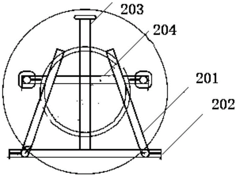
图4为本实用新型实施例提供的烟斗式吊架主视图;Fig. 4 is the front view of the pipe hanger provided by the embodiment of the utility model;
图5为本实用新型实施例提供的烟斗式吊架侧视图。Fig. 5 is a side view of the pipe hanger provided by the embodiment of the present invention.
其中:101、第一支撑杆;102、第二支撑杆;103、挂耳;104、绳索;201、曲臂;202、连接杆;203、第五支撑杆;204、第四支撑杆;205、第三支撑杆。Among them: 101, the first support rod; 102, the second support rod; 103, the hanging ear; 104, the rope; 201, the curved arm; 202, the connecting rod; 203, the fifth support rod; 204, the fourth support rod; 205 , the third support rod.
具体实施方式Detailed ways
为使本实用新型实施例的目的、技术方案和优点更加清楚,下面将结合附图对本实用新型的技术方案进行清楚、完整地描述,显然,所描述的实施例是本实用新型一部分实施例,而不是全部的实施例。基于本实用新型中的实施例,本领域普通技术人员在没有做出创造性劳动前提下所获得的所有其他实施例,都属于本实用新型保护的范围。In order to make the purpose, technical solutions and advantages of the embodiments of the utility model clearer, the technical solutions of the utility model will be clearly and completely described below in conjunction with the accompanying drawings. Obviously, the described embodiments are part of the embodiments of the utility model. rather than all examples. Based on the embodiments of the present utility model, all other embodiments obtained by persons of ordinary skill in the art without making creative efforts belong to the scope of protection of the present utility model.
目前,汽车提升存在着操作不便,拆卸困难,使用寿命短的技术问题,基于此,本实用新型实施例提供的一种烟斗式吊具及其支撑架,可以缓解现有技术中汽车提升存在着操作不便,拆卸困难,使用寿命短的技术问题,拆卸简单,使用便捷,使用寿命长,安全性高。At present, there are technical problems such as inconvenient operation, difficult disassembly, and short service life in automobile lifting. Inconvenient operation, difficult disassembly, technical problems of short service life, simple disassembly, convenient use, long service life and high safety.
为便于对本实施例进行理解,首先对本实用新型实施例所公开的一种烟斗式吊具及其支撑架进行详细介绍。In order to facilitate the understanding of this embodiment, a pipe-type spreader and its supporting frame disclosed in the embodiment of the present utility model are firstly introduced in detail.
实施例一:Embodiment one:
本实用新型提供了一种烟斗式吊具及其支撑架,所述一种烟斗式吊具除包括绳索以及卸扣外,还包括烟斗式吊架;The utility model provides a pipe-type hanger and its supporting frame. The pipe-type hanger not only includes a rope and a shackle, but also includes a pipe-type hanger;
可选择的,本实用新型绳索采用钢丝绳;Optionally, the rope of the utility model adopts a steel wire rope;
结合图至图3,所述烟斗式吊架的数量为四个,每个待提升车辆轮胎的外侧安装有所述烟斗式吊架,所述绳索与所述烟斗式吊架相连并利用所述烟斗式吊架将车辆吊起;With reference to Figure 3, the number of the pipe hangers is four, and the outside of each vehicle tire to be lifted is equipped with the pipe hangers, the ropes are connected with the pipe hangers and utilize the The pipe hanger lifts the vehicle;
所述支撑架包括第一支撑杆101、第二支撑杆102以及挂耳103;The support frame includes a
所述支撑架位于所述待提升车辆的正上方且所述支撑架的中心点与所述待提升车辆的重心位于同一垂直线上;The support frame is located directly above the vehicle to be lifted and the center point of the support frame is on the same vertical line as the center of gravity of the vehicle to be lifted;
所述第一支撑杆101与所述第二支撑杆102构成矩形,所述挂耳103位于所述第一支撑杆101的两端;The
所述绳索的末端穿过所述支撑架对应位置的挂耳103,以使支撑架对所述绳索进行支撑。The end of the rope passes through the hanging
进一步的,在本实用新型提供的实施例可知,挂耳103位于由所述第一支撑杆101、第二支撑杆102构成的矩形的靠近直角处,且位于所述待提升车辆的正上方,每个轮胎的正上方的挂耳103为绳索的末端穿过所述支撑架对应位置的挂耳103;Further, in the embodiment provided by the present utility model, it can be seen that the hanging
实施例二:Embodiment two:
结合图4以及图5,在本实用新型提供的实施例二中,对前述烟斗式吊架进行了阐述;With reference to Fig. 4 and Fig. 5, in the second embodiment provided by the utility model, the aforementioned pipe hanger is described;
具体的,所述烟斗式吊架包括连接杆202、第三支撑杆205、第四支撑杆204、第五支撑杆203以及曲臂201;Specifically, the pipe hanger includes a connecting
所述曲臂201的数量为两根且位于所述连接杆202的两侧,一根曲臂201的一端与所述连接杆202的一侧固定连接,另一根曲臂201的一端与所述连接杆202的另一侧固定连接;The quantity of described
可选择的,所述第三支撑杆205与所述曲臂201呈一体结构,以增加所述烟斗式吊架的抗拉强度;Optionally, the
所述第三支撑杆205的数量为两根,所述第三支撑杆205位于连接杆202的两侧且所述第三支撑杆205与所述连接杆202、所述曲臂201构成的平面垂直,所述第三支撑杆205与所述曲臂201固定连接;The number of the
所述第四支撑杆204分别与两根所述曲臂201固定连接,且与所述连接杆202平行放置;The
进一步的,所述曲臂201预所述连接杆202焊接;Further, the
所述第五支撑杆203与所述连接杆202以及所述第四支撑杆204均固定连接;The
进一步的,所述第四支撑杆204的两端分别与两根所述曲臂201焊接Further, both ends of the
所述曲臂201以及所述连接杆202为空心结构,以使所述绳索依次穿过所述曲臂201、连接杆202以及另一根曲臂201;The
进一步的,所述连接杆202、所述第三支撑杆205、所述第四支撑杆204、所述第五支撑杆203以及所述曲臂201均采用空心无缝钢管;Further, the connecting
所述连接杆202的长度小于待提升车辆轮胎外径。The length of the connecting
进一步的,为了使得轮胎与吊具更为贴合,在本实用新型提供的实施例中,所述曲臂201与所述第三支撑杆205的连接处呈圆角。Further, in order to make the tire fit better with the spreader, in the embodiment provided by the present utility model, the connection between the
优选的,为了使得绳索末端的距离更加接近,便于后续穿过挂耳103,第五支撑杆203的顶部所述具有两个通孔,通孔所在的平面与所述第五支撑杆203垂直,所述绳索的末端穿过靠近绳索末端的通孔。Preferably, in order to make the distance between the ends of the ropes closer to facilitate subsequent passing through the hanging
通过上述实施方式,可以使绳索与所述烟斗式吊架相连,同时将所述烟斗式吊架安装于待提升汽车的外侧,配合支撑架即可实现对汽车的提升。Through the above embodiment, the rope can be connected with the pipe hanger, and at the same time, the pipe hanger is installed on the outside of the car to be lifted, and the car can be lifted by cooperating with the support frame.
为了使得所述烟斗式吊架与待提升汽车贴合,所述曲臂201与所述第三支撑杆205的连接处呈圆角;In order to make the pipe hanger fit the car to be lifted, the connection between the
为了使得绳索末端距离更近,便于后续穿过支撑架的挂耳103,所述第五支撑杆203的顶部所述具有两个通孔(图中未示出),通孔所在的平面与所述第五支撑杆203垂直,所述绳索的末端穿过对应的通孔。In order to make the distance between the ends of the ropes closer, and to facilitate subsequent passing through the
实施例三:Embodiment three:
结合图1,本实用新型实施例三对前述支撑架的做了进一步阐述:In conjunction with Fig. 1, the third embodiment of the utility model further elaborates on the aforementioned support frame:
优选的,所述第一支撑杆101每端的挂耳103的数量为多个。Preferably, the number of hanging
可选择的,所述第一支撑杆101每端的挂耳103的数量为三个。Optionally, the number of hanging
优选的,所述第一支撑杆101的长度为6米,所述第二支撑杆102的长度为3米。Preferably, the length of the
实施例三:Embodiment three:
结合图1至图5,本实用新型实施例二对前述实施例的工作进行了阐述,具体的,将所述烟斗式吊架安装于轮胎的外侧,由于所述连接杆202的长度小于待提升汽车轮胎的外径,因此,所述第三支撑杆205将待提升的轮胎卡住,所述绳索穿过所述烟斗式吊架,所述绳索的末端穿过所述支撑架对应的挂耳103,利用所述卸扣即可实现对车辆的提升;1 to 5, Embodiment 2 of the present invention describes the work of the foregoing embodiments. Specifically, the pipe hanger is installed on the outside of the tire. Since the length of the connecting
本实用新型具有如下优点:The utility model has the following advantages:
1)使用简单:利用烟斗式吊架对所述绳索进行定位以及导向,对烟斗式吊架进行安装,安装简单,拆卸方便;1) Easy to use: use the pipe hanger to locate and guide the rope, and install the pipe hanger, which is easy to install and disassemble;
2)安全性强:烟斗式吊架在不移动车辆的情况下即可实现分离,相较于现有技术利用绳索直接吊起,提高了安全性。2) Strong safety: the pipe hanger can be separated without moving the vehicle, which improves the safety compared with the prior art that uses ropes to directly lift.
3)使用寿命长:相较于现有技术直接用绳索吊起,减少了磨损,提高了使用寿命。3) Long service life: Compared with the prior art, it is directly hoisted with ropes, which reduces wear and improves service life.
除非另外具体说明,否则在这些实施例中阐述的部件和步骤的相对步骤、数字表达式和数值并不限制本实用新型的范围。Relative steps, numerical expressions and numerical values of components and steps set forth in these embodiments do not limit the scope of the present invention unless specifically stated otherwise.
最后应说明的是:以上所述实施例,仅为本实用新型的具体实施方式,用以说明本实用新型的技术方案,而非对其限制,本实用新型的保护范围并不局限于此,尽管参照前述实施例对本实用新型进行了详细的说明,本领域的普通技术人员应当理解:任何熟悉本技术领域的技术人员在本实用新型揭露的技术范围内,其依然可以对前述实施例所记载的技术方案进行修改或可轻易想到变化,或者对其中部分技术特征进行等同替换;而这些修改、变化或者替换,并不使相应技术方案的本质脱离本实用新型实施例技术方案的精神和范围,都应涵盖在本实用新型的保护范围之内。因此,本实用新型的保护范围应所述以权利要求的保护范围为准。It should be noted that at last: the above-described embodiment is only the specific implementation manner of the present utility model, in order to illustrate the technical scheme of the present utility model, rather than it is limited, and the protection scope of the present utility model is not limited thereto, Although the utility model has been described in detail with reference to the aforementioned embodiments, those of ordinary skill in the art should understand that any person familiar with the technical field can still describe the aforementioned embodiments within the technical scope disclosed in the utility model. Modifications or changes can be easily imagined in the technical solutions, or equivalent replacement of some of the technical features; and these modifications, changes or replacements do not make the essence of the corresponding technical solutions deviate from the spirit and scope of the technical solutions of the embodiments of the present utility model. All should be covered within the protection scope of the present utility model. Therefore, the protection scope of the present utility model should be based on the protection scope of the claims.
Claims (10)
Priority Applications (1)
| Application Number | Priority Date | Filing Date | Title |
|---|---|---|---|
| CN202223262991.XU CN218619844U (en) | 2022-12-06 | 2022-12-06 | A kind of pipe spreader and its supporting frame |
Applications Claiming Priority (1)
| Application Number | Priority Date | Filing Date | Title |
|---|---|---|---|
| CN202223262991.XU CN218619844U (en) | 2022-12-06 | 2022-12-06 | A kind of pipe spreader and its supporting frame |
Publications (1)
| Publication Number | Publication Date |
|---|---|
| CN218619844U true CN218619844U (en) | 2023-03-14 |
Family
ID=85455019
Family Applications (1)
| Application Number | Title | Priority Date | Filing Date |
|---|---|---|---|
| CN202223262991.XU Expired - Fee Related CN218619844U (en) | 2022-12-06 | 2022-12-06 | A kind of pipe spreader and its supporting frame |
Country Status (1)
| Country | Link |
|---|---|
| CN (1) | CN218619844U (en) |
-
2022
- 2022-12-06 CN CN202223262991.XU patent/CN218619844U/en not_active Expired - Fee Related
Similar Documents
| Publication | Publication Date | Title |
|---|---|---|
| CN202080812U (en) | Dedicated sling system for large-scaled reinforcing cage | |
| CN109137758A (en) | A kind of self-anchored suspension bridge cable construction technology | |
| CN207748760U (en) | A kind of bridge crane of hoisting large-size drainpipe | |
| CN209778055U (en) | A general lifting device for lifting cylinder head | |
| CN203545535U (en) | Auxiliary arm and crane | |
| CN221680624U (en) | Crown block structure of double crown block cable crane | |
| CN212450260U (en) | Convenient auxiliary device of tubular product transport | |
| CN108946475A (en) | A kind of overturning Lift-on/Lift-off System and hanging method for horizontal equipment | |
| CN208869199U (en) | A kind of overturning Lift-on/Lift-off System for horizontal equipment | |
| CN208413637U (en) | A kind of crane hanger | |
| CN215479334U (en) | Boom and tower crane | |
| CN207943826U (en) | High-speed railway bridge floor series concrete multi-transportation vehicle | |
| CN206693060U (en) | A kind of hoisting device for the lifting of suspension bridge saddle bearing plate | |
| CN101402435B (en) | Special sling for inner bore of step and its use method | |
| CN111847290A (en) | Lifting machine | |
| CN208054723U (en) | A kind of Pipe installing application c-type suspension hook | |
| CN201172572Y (en) | Lifting beam device for handling steel tubes | |
| CN203173677U (en) | Hoisting tool for replacing plate hook of large traveling crane | |
| CN203439948U (en) | Gantry lifting frame for cableway | |
| CN206841277U (en) | Lifting and delivery head base device for electric pole conveying | |
| CN207030724U (en) | New dipped type cord fabric hanging device | |
| CN212174274U (en) | Large-span suspension bridge cable crane traction system with combined type sports car and traction tackle | |
| CN205616542U (en) | Cast tube tube drawing car wheel quick assembly disassembly device | |
| CN223509490U (en) | Precast beam overhead hoist for bridge construction | |
| CN215711312U (en) | Truss arm head and crane |
Legal Events
| Date | Code | Title | Description |
|---|---|---|---|
| GR01 | Patent grant | ||
| GR01 | Patent grant | ||
| CF01 | Termination of patent right due to non-payment of annual fee | ||
| CF01 | Termination of patent right due to non-payment of annual fee |
Granted publication date: 20230314 |