CN218608953U - Compounding preparation jar of compound fertilizer production usefulness - Google Patents
Compounding preparation jar of compound fertilizer production usefulness Download PDFInfo
- Publication number
- CN218608953U CN218608953U CN202221851455.0U CN202221851455U CN218608953U CN 218608953 U CN218608953 U CN 218608953U CN 202221851455 U CN202221851455 U CN 202221851455U CN 218608953 U CN218608953 U CN 218608953U
- Authority
- CN
- China
- Prior art keywords
- fixedly connected
- mixing
- tank
- motor
- shaft
- Prior art date
- Legal status (The legal status is an assumption and is not a legal conclusion. Google has not performed a legal analysis and makes no representation as to the accuracy of the status listed.)
- Expired - Fee Related
Links
- 239000003337 fertilizer Substances 0.000 title claims abstract description 64
- 150000001875 compounds Chemical class 0.000 title claims abstract description 25
- 238000004519 manufacturing process Methods 0.000 title claims abstract description 18
- 238000002360 preparation method Methods 0.000 title claims abstract description 18
- 238000013329 compounding Methods 0.000 title claims abstract description 11
- 238000002156 mixing Methods 0.000 claims abstract description 83
- 238000003756 stirring Methods 0.000 claims description 24
- 239000000463 material Substances 0.000 claims description 22
- 238000007599 discharging Methods 0.000 claims description 12
- 230000000149 penetrating effect Effects 0.000 claims description 10
- 238000003860 storage Methods 0.000 claims description 5
- 230000008859 change Effects 0.000 abstract description 7
- 230000007659 motor function Effects 0.000 abstract description 2
- 230000002508 compound effect Effects 0.000 abstract 1
- 230000000694 effects Effects 0.000 description 9
- 230000006870 function Effects 0.000 description 4
- 230000009471 action Effects 0.000 description 3
- 239000002994 raw material Substances 0.000 description 3
- 230000002337 anti-port Effects 0.000 description 2
- 235000021049 nutrient content Nutrition 0.000 description 2
- 230000009286 beneficial effect Effects 0.000 description 1
- 230000004720 fertilization Effects 0.000 description 1
- 239000004615 ingredient Substances 0.000 description 1
- 230000004048 modification Effects 0.000 description 1
- 238000012986 modification Methods 0.000 description 1
- 235000015097 nutrients Nutrition 0.000 description 1
- 230000000704 physical effect Effects 0.000 description 1
- 230000001737 promoting effect Effects 0.000 description 1
- 239000000126 substance Substances 0.000 description 1
Images


Classifications
-
- Y—GENERAL TAGGING OF NEW TECHNOLOGICAL DEVELOPMENTS; GENERAL TAGGING OF CROSS-SECTIONAL TECHNOLOGIES SPANNING OVER SEVERAL SECTIONS OF THE IPC; TECHNICAL SUBJECTS COVERED BY FORMER USPC CROSS-REFERENCE ART COLLECTIONS [XRACs] AND DIGESTS
- Y02—TECHNOLOGIES OR APPLICATIONS FOR MITIGATION OR ADAPTATION AGAINST CLIMATE CHANGE
- Y02P—CLIMATE CHANGE MITIGATION TECHNOLOGIES IN THE PRODUCTION OR PROCESSING OF GOODS
- Y02P60/00—Technologies relating to agriculture, livestock or agroalimentary industries
- Y02P60/20—Reduction of greenhouse gas [GHG] emissions in agriculture, e.g. CO2
- Y02P60/21—Dinitrogen oxide [N2O], e.g. using aquaponics, hydroponics or efficiency measures
Landscapes
- Fertilizers (AREA)
Abstract
The utility model discloses a compounding preparation jar of compound fertilizer production usefulness belongs to compound fertilizer production technical field, wherein includes the blending tank, blending tank side fixedly connected with feed tank, the inside baffle that is provided with of feed tank, surface fixedly connected with rack under the baffle, feed tank side fixedly connected with fixed plate, fixed plate upper surface fixedly connected with first motor through setting up first motor, first gear and rack, when needs change fertilizer and fall into the speed of blending tank, only need through the first motor function of control switch control to drive first gear revolve, under the meshing of first gear and rack, thereby drive the baffle and remove, simultaneously under the cooperation of slider and spout, make the baffle can move steadily, thereby change the size of blanking hole in the feed tank, can change the speed that fertilizer fell into the blending tank, make things convenient for people to control the speed of fertilizer blanking according to the compound effect of fertilizer, improve the mixing efficiency of fertilizer.
Description
Technical Field
The utility model relates to a compound fertilizer production technical field, more specifically say, it relates to a compounding preparation jar of compound fertilizer production usefulness.
Background
The compound fertilizer is a chemical fertilizer containing two or more nutrient elements, has the advantages of high nutrient content, few side ingredients, good physical properties and the like, plays an important role in balancing fertilization, improving the utilization rate of the fertilizer and promoting the high and stable yield of crops, and in the production process of the compound fertilizer, different raw materials need to be added into a mixer according to a certain proportion for mixing, so that the various raw materials are mutually fused, and the integral nutrient content is improved.
Patent grant number is CN215610886U, a compounding preparation jar of compound fertilizer production usefulness is disclosed, though can carry out abundant mixing to the raw materials, but the device can only be got to the manual work and weighed a certain amount of fertilizer, then mix in pouring into the preparation jar entirely, because the material of once only pouring into in the preparation jar is too much, the complete mixing need consume longer time, the efficiency of mixing is lower, and the fertilizer in the preparation jar is more, weight is heavier, need use great strength when taking out the sliding plate row material, inconvenient row material.
SUMMERY OF THE UTILITY MODEL
(1) Technical problem to be solved
Not enough to prior art exists, the utility model aims to provide a compounding preparation jar of compound fertilizer production usefulness, it has the compounding efficiency that can improve compound fertilizer, and the convenient characteristics of arranging the material.
(2) Technical scheme
In order to realize the above purpose, the utility model provides a compounding preparation jar of compound fertilizer production usefulness, including the blending tank, blending tank side fixedly connected with feed tank, the inside baffle that is provided with of feed tank, surface fixedly connected with rack under the baffle, feed tank side fixedly connected with fixed plate, fixed surface fixedly connected with first motor on the fixed plate, the first gear of first motor output shaft one end fixedly connected with, first gear and rack mesh mutually, blending tank lower extreme fixedly connected with discharge gate, be provided with ejection of compact subassembly in the discharge gate, fixed surface is connected with the mount on the blending tank, the inside fixedly connected with agitator motor of mount, the first (mixing) shaft of agitator motor output shaft lower extreme fixedly connected with, first (mixing) shaft fixed surface is connected with the driving gear.
When using the compounding preparation jar of this technical scheme's a compound fertilizer production usefulness, through the operation of the first motor of control switch control, from driving first gear revolve, under the meshing of first gear and rack, drive the baffle and remove to change the size in blanking hole in the feeding jar, can change the speed that fertilizer fell into the blending tank, make things convenient for people to control the speed of fertilizer blanking according to the mixed effect of fertilizer.
Further, the discharging assembly comprises a second motor, the second motor is fixedly connected to the side face of the discharging port, one end of an output shaft of the second motor is fixedly connected with a material guide rotating shaft, a first bearing is arranged on the surface of the discharging port in a penetrating mode, the material guide rotating shaft is arranged in the first bearing in a penetrating mode, a second bearing is fixedly connected to the inner wall of the discharging port, one end of the material guide rotating shaft is arranged in the second bearing in a penetrating mode, and a plurality of material shifting plates are fixedly connected to the surface of the material guide rotating shaft.
Further, a third bearing is arranged on the surface of the mixing tank in a penetrating mode, the first stirring shaft is arranged in the third bearing in a penetrating mode, a fourth bearing is arranged on the surface of the mixing tank in a penetrating mode, a second stirring shaft is arranged in the fourth bearing in a penetrating mode, a driven gear is fixedly connected to the surface of the second stirring shaft, the driving gear is meshed with the driven gear, and a plurality of stirring blades are fixedly connected to the surfaces of the first stirring shaft and the second stirring shaft.
Further, two sliding blocks are symmetrically and fixedly connected to the side faces of the baffle plates, two sliding grooves are symmetrically formed in the surface of the feeding tank, the sliding blocks are connected in the sliding grooves in a sliding mode, the number of the feeding tanks is two, and the two sliding blocks are symmetrically arranged on two sides of the mixing tank.
Further, the mixing tank lower extreme is provided with the bottom plate, bottom plate upper surface fixed connection has the support frame, support frame fixed connection is on the mixing tank surface, the bottom plate upper surface overlap joint has the storage case.
Further, the mixing tank openly fixedly connected with control switch, the inside microprocessor that is provided with of control switch, feed tank surface mosaic has the scale observation window.
(3) Advantageous effects
To sum up, the utility model discloses following beneficial effect has:
1. by arranging the first motor, the first gear and the rack, when the speed of fertilizer falling into the mixing tank needs to be changed, the first motor is controlled to operate only by controlling the switch, so that the first gear is driven to rotate, the baffle is driven to move under the meshing of the first gear and the rack, and meanwhile, under the matching of the sliding block and the sliding groove, the baffle can stably move, so that the size of a material falling hole in the feeding tank is changed, the speed of fertilizer falling into the mixing tank can be changed, people can conveniently control the fertilizer falling speed according to the mixing effect of the fertilizer, and the mixing efficiency of the fertilizer is improved;
2. by arranging the discharging assembly, when the mixed compound fertilizer is required to be discharged from the mixing tank, the second motor is controlled to operate only by the control switch, so that the guide rotating shaft is driven to rotate, the fertilizer in the mixing tank can be stirred out at a constant speed under the action of the plurality of stirring plates, the compound fertilizer is prevented from being stacked at the discharging opening, the compound fertilizer is convenient to discharge from the mixing tank, the discharging efficiency is improved, and meanwhile, the operation is convenient;
3. through setting up agitator motor, driving gear and driven gear, when needs mix the stirring to fertilizer, only need to control agitator motor function through control switch, can drive the driving gear and rotate, under driving gear and driven gear's intermeshing, thereby it is rotatory according to opposite direction to drive two (mixing) shafts, under a plurality of stirring vane's effect, can carry out abundant mixed stirring to fertilizer, simultaneously because two sets of stirring vane antiport, can break up the fertilizer of caking, the mixed effect of fertilizer has been improved.
Drawings
In order to clearly illustrate the embodiments of the present invention or the technical solutions in the prior art, the drawings used in the embodiments or the descriptions in the prior art will be briefly described below, it is obvious that the drawings in the following description are only one embodiment of the present invention, and other drawings can be obtained by those skilled in the art without creative efforts.
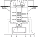
FIG. 1 is a schematic view of the front sectional structure of the present invention;
FIG. 2 is a schematic view of the structure of the middle feeding tank of the present invention;
FIG. 3 is a schematic structural view of the discharging assembly of the present invention;
fig. 4 is a schematic view of the front view structure of the present invention.
The labels in the figures are:
1. a mixing tank; 2. a feed tank; 3. a baffle plate; 4. a rack; 5. a fixing plate; 6. a first motor; 7. a first gear; 8. a discharge port; 9. a discharge assembly; 901. a second motor; 902. a material guiding rotating shaft; 903. a first bearing; 904. a second bearing; 905. a kick-out plate; 10. a slider; 11. a chute; 12. a stirring motor; 13. a first stirring shaft; 14. a third bearing; 15. a driving gear; 16. a fourth bearing; 17. a second stirring shaft; 18. a driven gear; 19. a stirring blade; 20. a base plate; 21. a support frame; 22. a material storage box; 23. and controlling the switch.
Detailed Description
In order to make the technical means, creation features, achievement purposes and functions of the present invention easy to understand, the following description is made for the technical solution of the present invention in the embodiments to explain the present invention clearly and completely, obviously, the described embodiments are only a part of the embodiments of the present invention, but not all the embodiments.
Example (b):
the present invention will be described in further detail with reference to the accompanying fig. 1-4.
Referring to fig. 1-4, the present invention provides a technical solution: the utility model provides a compounding preparation jar of compound fertilizer production usefulness, including blending tank 1, 1 side fixedly connected with feeding tank 2 of blending tank, 2 inside baffles 3 that are provided with of feeding tank, surface fixedly connected with rack 4 under 3 baffles, 2 side fixedly connected with fixed plate 5 of feeding tank, surface fixedly connected with first motor 6 on the fixed plate 5, the first gear 7 of first motor 6 output shaft one end fixedly connected with, first gear 7 meshes with rack 4 mutually, through controlling first motor 6 function, drive first gear 7 and rotate, under the meshing of first gear 7 and rack 4, it removes to drive baffle 3, change the size in blanking hole in feeding tank 2, can change the speed that fertilizer fell into blending tank 1, 1 lower extreme fixedly connected with discharge gate 8 of blending tank, be provided with ejection of compact subassembly 9 in the discharge gate 8, 1 upper surface fixedly connected with mount of blending tank, the inside fixedly connected with agitator motor 12 of mount, agitator motor 12 output shaft lower extreme fixedly connected with first (mixing) shaft 13, first (mixing shaft 13) surface fixedly connected with driving gear 15.
Specifically, ejection of compact subassembly 9 includes second motor 901, second motor 901 fixed connection is in 8 sides of discharge gate, second motor 901 output shaft one end fixedly connected with guide pivot 902, first bearing 903 is worn to be equipped with on the 8 surfaces of discharge gate, guide pivot 902 is worn to establish in first bearing 903, 8 inner wall fixedly connected with second bearings 904 of discharge gate, guide pivot 902 one end is worn to establish in second bearing 904, a plurality of switch plates 905 of guide pivot 902 fixed surface connection.
Through adopting above-mentioned technical scheme, when the compound fertilizer that will mix the completion is discharged from blending tank 1, through the function of control switch 23 control second motor 901, drive guide pivot 902 and rotate, under the effect of a plurality of switch-plates 905, can dial out the fertilizer at the uniform velocity in blending tank 1, make things convenient for compound fertilizer to discharge from blending tank 1.
Specifically, third bearing 14 wears to be equipped with on the surface of blending tank 1, and first (mixing) shaft 13 wears to establish in third bearing 14, and fourth bearing 16 wears to be equipped with on the surface of blending tank 1, wears to be equipped with second (mixing) shaft 17 among the fourth bearing 16, and second (mixing) shaft 17 fixed surface is connected with driven gear 18, and driving gear 15 meshes with driven gear 18 mutually, and first (mixing) shaft 13 and the equal fixedly connected with a plurality of stirring vane 19 in second (mixing) shaft 17 surface.
Through adopting above-mentioned technical scheme, through controlling agitator motor 12 function, drive driving gear 15 and rotate, under driving gear 15 and driven gear 18's intermeshing, it is rotatory according to opposite direction to drive two (mixing) shafts, under a plurality of stirring vane 19's effect, can carry out abundant mixed stirring to fertilizer, because two sets of stirring vane 19 antiport simultaneously can break up the fertilizer of caking.
Specifically, two sliders 10 of 3 side symmetry fixedly connected with of baffle, two spouts 11 have been seted up to 2 surface symmetries of feeding jar, and slider 10 sliding connection makes baffle 3 can move steadily in spout 11 under the cooperation of slider 10 and spout 11, and feeding jar 2 is total two to the symmetry sets up in 1 both sides of blending tank.
Specifically, 1 lower extreme of blending tank is provided with bottom plate 20, and fixed surface is connected with support frame 21 on bottom plate 20, and support frame 21 fixed connection has storage case 22 on 1 surface of blending tank, 20 upper surface overlap joints of bottom plate, and the fertilizer after finishing mixing falls into storage case 22 and collects under ejection of compact subassembly 9's effect.
Specifically, 1 openly fixedly connected with control switch 23 of blending tank, the inside microprocessor that is provided with of control switch 23, 2 surperficial inlays of feeding tank have the scale observation window.
The utility model discloses a theory of operation does: when the fertilizer mixer is used, the baffle 3 completely plugs the feeding tanks 2, firstly, fertilizers with a certain proportion are poured into the two feeding tanks 2 respectively, then the switch 23 is controlled to control the first motor 6 to operate according to the proportion of the two fertilizers respectively, the first gear 7 is driven to rotate, the baffle 3 is driven to move under the meshing of the first gear 7 and the rack 4, the size of a blanking hole in the feeding tank 2 is changed, so that the speed of each fertilizer falling into the mixing tank 1 is changed, people can conveniently control the fertilizer blanking speed according to the mixing effect of the fertilizers and the proportion of the fertilizers, after the fertilizers fall into the mixing tank 1, the stirring motor 12 is controlled to operate through the control switch 23, the driving gear 15 is driven to rotate, under the mutual meshing of the driving gear 15 and the driven gear 18, the two stirring shafts are driven to rotate in opposite directions, under the action of the stirring blades 19, the fertilizers are fully mixed and stirred, after the mixing is finished, the operation of the second motor 901 is controlled through the control switch 23, the material guiding rotating shaft 902 is driven to rotate, under the action of the stirring plates 905, the fertilizer in the mixing tank 1 is stirred, the fertilizer mixer is prevented from being piled up at a uniform speed 8, and the fertilizer can be conveniently discharged from the mixing tank 1, and the discharge port can be conveniently used.
The present embodiment is only for explaining the present invention, and it is not limited to the present invention, and those skilled in the art can make modifications to the present embodiment without inventive contribution as required after reading the present specification, but all of them are protected by patent laws within the scope of the claims of the present invention.
Claims (6)
1. The utility model provides a compounding preparation jar of compound fertilizer production usefulness, includes blending tank (1), its characterized in that: mixing tank (1) side fixedly connected with feeding jar (2), inside baffle (3) that is provided with of feeding jar (2), fixed surface is connected with rack (4) under baffle (3), feeding jar (2) side fixedly connected with fixed plate (5), fixed surface is connected with first motor (6) on fixed plate (5), first motor (6) first gear of output shaft one end fixedly connected with (7), first gear (7) mesh with rack (4) mutually, mixing tank (1) lower extreme fixedly connected with discharge gate (8), be provided with ejection of compact subassembly (9) in discharge gate (8), fixed surface is connected with the mount on mixing tank (1), inside fixedly connected with agitator motor (12) of mount, agitator motor (12) output shaft lower extreme fixedly connected with first (mixing) shaft (13), first (mixing) shaft (13) fixed surface is connected with driving gear (15).
2. The mixing material preparation tank for compound fertilizer production according to claim 1, characterized in that: the discharging assembly (9) comprises a second motor (901), the second motor (901) is fixedly connected to the side face of the discharging port (8), one end of an output shaft of the second motor (901) is fixedly connected with a material guiding rotating shaft (902), a first bearing (903) is arranged on the surface of the discharging port (8) in a penetrating mode, the material guiding rotating shaft (902) is arranged in the first bearing (903) in a penetrating mode, a second bearing (904) is fixedly connected to the inner wall of the discharging port (8), one end of the material guiding rotating shaft (902) is arranged in the second bearing (904) in a penetrating mode, and a plurality of shifting plates (905) are fixedly connected to the surface of the material guiding rotating shaft (902).
3. The mixing material preparation tank for compound fertilizer production according to claim 1, characterized in that: third bearing (14) are worn to be equipped with on blending tank (1) surface, wear to establish in third bearing (14) first (mixing) shaft (13), fourth bearing (16) are worn to be equipped with on blending tank (1) surface, wear to be equipped with second (mixing) shaft (17) in fourth bearing (16), second (mixing) shaft (17) fixed surface is connected with driven gear (18), driving gear (15) and driven gear (18) mesh mutually, first (mixing) shaft (13) and second (mixing) shaft (17) equal fixed surface are connected with a plurality of stirring vane (19).
4. The mixing material preparation tank for compound fertilizer production according to claim 1, characterized in that: baffle (3) side symmetry fixedly connected with two sliders (10), two spout (11) have been seted up to feeding tank (2) surface symmetry, slider (10) sliding connection is in spout (11), feeding tank (2) are total two to the symmetry sets up in blending tank (1) both sides.
5. The mixing material preparation tank for compound fertilizer production according to claim 1, characterized in that: the mixing tank is characterized in that a bottom plate (20) is arranged at the lower end of the mixing tank (1), a support frame (21) is fixedly connected to the upper surface of the bottom plate (20), the support frame (21) is fixedly connected to the surface of the mixing tank (1), and a storage box (22) is lapped on the upper surface of the bottom plate (20).
6. The mixing material preparation tank for compound fertilizer production according to claim 1, characterized in that: mixing tank (1) openly fixedly connected with control switch (23), control switch (23) inside is provided with microprocessor, feed tank (2) surface mosaic has the scale observation window.
Priority Applications (1)
| Application Number | Priority Date | Filing Date | Title |
|---|---|---|---|
| CN202221851455.0U CN218608953U (en) | 2022-07-19 | 2022-07-19 | Compounding preparation jar of compound fertilizer production usefulness |
Applications Claiming Priority (1)
| Application Number | Priority Date | Filing Date | Title |
|---|---|---|---|
| CN202221851455.0U CN218608953U (en) | 2022-07-19 | 2022-07-19 | Compounding preparation jar of compound fertilizer production usefulness |
Publications (1)
| Publication Number | Publication Date |
|---|---|
| CN218608953U true CN218608953U (en) | 2023-03-14 |
Family
ID=85457628
Family Applications (1)
| Application Number | Title | Priority Date | Filing Date |
|---|---|---|---|
| CN202221851455.0U Expired - Fee Related CN218608953U (en) | 2022-07-19 | 2022-07-19 | Compounding preparation jar of compound fertilizer production usefulness |
Country Status (1)
| Country | Link |
|---|---|
| CN (1) | CN218608953U (en) |
-
2022
- 2022-07-19 CN CN202221851455.0U patent/CN218608953U/en not_active Expired - Fee Related
Similar Documents
| Publication | Publication Date | Title |
|---|---|---|
| CN218608953U (en) | Compounding preparation jar of compound fertilizer production usefulness | |
| CN219482472U (en) | Mixing arrangement of solid compound lead salt class stabilizer | |
| CN218981295U (en) | Multifunctional fertilizer mixing and stirring mechanism for seaweed fertilizer | |
| CN115779720B (en) | Mixing device and mixing method for processing high polymer materials | |
| CN202621086U (en) | Horizontal stirrer for mixing blending fertilizer | |
| CN208943923U (en) | A kind of granular material mixing feeding device | |
| CN212237075U (en) | Feeding and mixing device for mechanical automation processing | |
| CN215389023U (en) | Stirring subassembly is used in processing of chemical fertilizer anticaking agent | |
| CN213966371U (en) | Mixing mechanism for producing bulk blend fertilizer | |
| CN212385687U (en) | Foam concrete agitating unit | |
| CN211682970U (en) | PP material mixes painted mixer | |
| CN211329230U (en) | Fertilizer mixing arrangement is smashed to gardens soil | |
| CN213853985U (en) | Secondary progressive system for powder discharge of stirrer | |
| CN113546569A (en) | Battery production professional equipment mixer | |
| CN220143118U (en) | Chemical fertilizer proportioning and mixing device for blended fertilizer | |
| CN215610886U (en) | Compounding preparation jar of compound fertilizer production usefulness | |
| CN213611055U (en) | Starch sugar is with mixing thick liquid device | |
| CN218944941U (en) | Automatic batching device for refractory material production | |
| CN218530615U (en) | Petrochemical auxiliary agent production agitating unit | |
| CN220531275U (en) | Bacterial manure raw material blending kettle | |
| CN217414551U (en) | Mixing device for plastic gear machining | |
| CN212068476U (en) | Mixing machine for food processing | |
| CN220071359U (en) | Multi-raw material mixer | |
| CN221386056U (en) | Refractory material batching equipment | |
| CN215038923U (en) | Even dosing unit is used in concrete processing |
Legal Events
| Date | Code | Title | Description |
|---|---|---|---|
| GR01 | Patent grant | ||
| GR01 | Patent grant | ||
| CF01 | Termination of patent right due to non-payment of annual fee | ||
| CF01 | Termination of patent right due to non-payment of annual fee |
Granted publication date: 20230314 |