CN218607258U - Fixing device for head dissection - Google Patents
Fixing device for head dissection Download PDFInfo
- Publication number
- CN218607258U CN218607258U CN202222894285.0U CN202222894285U CN218607258U CN 218607258 U CN218607258 U CN 218607258U CN 202222894285 U CN202222894285 U CN 202222894285U CN 218607258 U CN218607258 U CN 218607258U
- Authority
- CN
- China
- Prior art keywords
- head
- sliding
- corpse
- brace table
- dissecting
- Prior art date
- Legal status (The legal status is an assumption and is not a legal conclusion. Google has not performed a legal analysis and makes no representation as to the accuracy of the status listed.)
- Active
Links
Images

Landscapes
- Accommodation For Nursing Or Treatment Tables (AREA)
Abstract
The utility model discloses a fixing device for head dissection, which belongs to the technical field of dissection auxiliary equipment and comprises a dissecting table, wherein a head supporting table is arranged on one side of the dissecting table, and a connecting component is arranged between the head supporting table and the dissecting table; the utility model discloses a cooperation of locating component and supporting pad is used, place in the top of supporting pad behind the corpse head that will dissect, user's accessible twist grip drives the direction of locating plate to the corpse head and compresses tightly, compress tightly the corpse head and fix on the supporting pad, with fixing the corpse head, prevent to remove at the in-process corpse head of dissecting, use through the cooperation of rubber base and supporting pad simultaneously, can prevent to cause the damage to it at the in-process of fixing the corpse, through coupling assembling's setting, can carry out the angle rotation to the head of corpse at the in-process of dissecting, so that the operator dissects the operation to the different positions of corpse head.
Description
Technical Field
The utility model relates to an anatomy auxiliary assembly technical field specifically is a head is dissected and is used fixing device.
Background
The existing fixing devices for head dissection are simply fixed by nails and are easy to damage the head of a corpse in the dissection process, and Chinese patent with application number CN201920372620.6 discloses a fixing support for head dissection of a corpse, which comprises a base, wherein a corpse head fixing device is arranged on the base, the corpse head fixing device comprises a plurality of fixing frames, and the fixing frames are connected with the base through horizontal arms arranged at the bottoms of the fixing frames; the top of the fixing frame is provided with a fixing frame threaded hole, and a dead head fixing screw is screwed in the fixing frame threaded hole. The utility model discloses a fixer is dissected to corpse head structure is firm, and the cost is reasonable, and detachable construction makes the utility model discloses easily accomodate and carry, for development of relevant teaching of corpse head anatomy structure, scientific research provide facility.
The head of the fixing device is fixed through the fixing screw in the actual use process, the pointed conical fixing screw easily damages the head of the corpse, and the fixed head of the corpse cannot be angularly rotated when the head of the corpse is dissected, so that the use flexibility of the fixing device is poor, and therefore the fixing device for head dissection is required to be provided.
SUMMERY OF THE UTILITY MODEL
An object of the utility model is to provide a fixing device is used in head dissection possesses and can prevent that fixed position from leading to the fact the damage to it when corpse head goes on fixing, can carry out the advantage of angle rotation in order to promote its use flexibility to the corpse head after fixing simultaneously to solve the problem that proposes in the above-mentioned background art.
In order to realize the above object, the utility model provides a fixing device is used in head dissection, including the dissection table, one side of dissection table is equipped with the head brace table, be equipped with between head brace table and the dissection table and carry out the coupling assembling that rotates the regulation to the use angle of head brace table, the head brace table rotates through coupling assembling and dissection table and links together, one side of head brace table still is equipped with and is used for carrying out the spacing subassembly fixed to the turned angle of head brace table, the equal symmetry in both sides is equipped with owing to carry out the locating component who fixes to dissecting the head around the head brace table, the locating component is fixed in the surface of head brace table through the slip subassembly connection.
Preferably, coupling assembling includes the connecting axle of fixed mounting in dissection table one side, the inside of head supporting bench sets up the spread groove with the connecting axle adaptation, the inner wall of spread groove is connected with the surperficial rotation of connecting axle, the one end of connecting axle runs through the spread groove and extends to the outside of spread groove.
Preferably, the limiting assembly comprises a limiting pipe fixedly installed on one side of the head supporting table, the surface of the connecting shaft is connected with the inner wall of the limiting pipe in a rotating mode, the surface of the limiting pipe is connected with a limiting rod in a threaded mode, and one end of the limiting rod penetrates through the limiting pipe and extends to the inner cavity of the limiting pipe to be attached to the surface of the connecting shaft.
Preferably, the sliding assembly comprises sliding grooves arranged on the front side and the rear side of the head supporting table, sliding plates are connected to the inner cavity of the sliding grooves in a sliding mode, sliding seats are connected to the front side and the rear side of the head supporting table in a sliding mode, and one side of each sliding plate penetrates through the corresponding sliding groove and extends to the outer portion of the corresponding sliding groove and the inner wall of each sliding seat to be fixedly connected.
Preferably, the surface of the sliding seat is in threaded connection with a locking rod, and one end of the locking rod penetrates through the sliding seat and extends to the inner cavity of the sliding seat to be attached to the surface of the head supporting table.
Preferably, locating component includes fixed mounting in the bracing piece at slide top, the top fixed mounting of bracing piece has the fixing base, the surface of fixing base inlays and is equipped with the screwed pipe, the inner chamber threaded connection of screwed pipe has the locating lever, the both ends of locating lever all run through the screwed pipe and extend to the outside of screwed pipe, the one end fixed mounting of locating lever has the handle, the other end of locating lever rotates through the connecting seat and is connected with the locating plate.
Preferably, the top fixed mounting of head supporting bench has the supporting pad, one side fixedly connected with rubber pad seat that the locating lever is kept away from to the locating plate.
Compared with the prior art, the beneficial effects of the utility model are that:
1. the utility model discloses a cooperation of locating component and supporting pad is used, after the corpse head that will dissect is placed at the top of supporting pad, user's accessible twist grip drives the direction of locating plate to the corpse head and compresses tightly, compress tightly the corpse head and fix on the supporting pad, fix the corpse head, prevent that the corpse head from removing in the process of dissecting, use through the cooperation of rubber pad seat and supporting pad simultaneously, can prevent to cause the damage to it in the fixed in-process of corpse, through the setting of coupling component, can carry out angle rotation to the head of corpse in the process of dissecting, so that the operator dissects the operation to the different positions of corpse head;
2. the utility model discloses a setting of spacing subassembly can carry out spacing fixed to the use angle behind the head supporting bench angle regulation, through the setting of slip subassembly, can remove locating component's application position to promote the flexibility that this device used.
Drawings
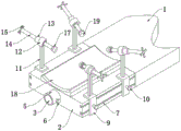
Fig. 1 is a schematic structural view of the present invention;
fig. 2 is a schematic structural view of the connection assembly and the limiting assembly of the present invention;
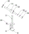
FIG. 3 is a schematic structural view of the sliding assembly and the positioning assembly of the present invention;
fig. 4 is the schematic structural diagram of the positioning rod and the threaded pipe connection of the present invention.
In the figure: 1. an dissecting table; 2. a head support table; 3. a connecting shaft; 4. connecting grooves; 5. a limiting pipe; 6. a limiting rod; 7. a chute; 8. a slide plate; 9. a slide base; 10. a locking lever; 11. a support bar; 12. a fixed seat; 13. a threaded pipe; 14. positioning a rod; 15. a handle; 16. a connecting seat; 17. positioning a plate; 18. a support pad; 19. a rubber cushion seat.
Detailed Description
The technical solutions in the embodiments of the present invention will be described clearly and completely with reference to the accompanying drawings in the embodiments of the present invention, and it is obvious that the described embodiments are only some embodiments of the present invention, not all embodiments. Based on the embodiments in the present invention, all other embodiments obtained by a person skilled in the art without creative efforts all belong to the protection scope of the present invention.
Referring to fig. 1-4, the utility model provides a fixing device for head dissection, including dissecting table 1, one side of dissecting table 1 is equipped with head supporting table 2, be equipped with between head supporting table 2 and dissecting table 1 and carry out the coupling assembling that rotates the angle of use of head supporting table 2 and adjust, head supporting table 2 rotates with dissecting table 1 through coupling assembling and links together, coupling assembling includes connecting axle 3 fixedly mounted in one side of dissecting table 1, the inside of head supporting table 2 is seted up the spread groove 4 with connecting axle 3 looks adaptation, the inner wall of spread groove 4 rotates with the surface of connecting axle 3 to be connected, one end of connecting axle 3 runs through spread groove 4 and extends to the outside of spread groove 4;
the use angle of the head support table 2 can be adjusted by the arrangement of the connecting assembly, when the head of the corpse is positioned and fixed at the top of the head support table 2 for dissection operation, if a user needs to adjust the dissection angle of the head of the corpse, the use angle of the head of the corpse can be rotated by rotating the head support table 2, and then the dissection angle of the head of the corpse is rotated, and when the head support table 2 is rotated, the connecting groove 4 can rotate on the surface of the connecting shaft 3;
preferably, one side of the head support platform 2 is further provided with a limiting assembly for fixing the rotation angle of the head support platform 2, the limiting assembly comprises a limiting pipe 5 fixedly installed on one side of the head support platform 2, the surface of the connecting shaft 3 is rotatably connected with the inner wall of the limiting pipe 5, the surface of the limiting pipe 5 is in threaded connection with a limiting rod 6, and one end of the limiting rod 6 penetrates through the limiting pipe 5 and extends to an inner cavity of the limiting pipe 5 to be attached to the surface of the connecting shaft 3;
through the arrangement of the limiting assembly, after the use angle of the head support platform 2 is adjusted, a user screws up the limiting rod 6 to limit and fix the use angle of the head support platform 2, and the limiting pipe 5 is driven to rotate on the surface of the connecting shaft 3 when the head support platform 2 rotates in an angle adjusting mode;
the front side and the rear side of the head supporting platform 2 are symmetrically provided with positioning components for fixing the dissected head, each positioning component comprises a supporting rod 11 fixedly installed at the top of a sliding seat 9, a fixed seat 12 is fixedly installed at the top of each supporting rod 11, a threaded pipe 13 is embedded in the surface of each fixed seat 12, an inner cavity of each threaded pipe 13 is in threaded connection with a positioning rod 14, two ends of each positioning rod 14 penetrate through the threaded pipe 13 and extend to the outside of the threaded pipe 13, one end of each positioning rod 14 is fixedly provided with a handle 15, the other end of each positioning rod 14 is rotatably connected with a positioning plate 17 through a connecting seat 16, each positioning component is connected and fixed to the surface of the head supporting platform 2 through a sliding component, each sliding component comprises sliding grooves 7 formed in the front side and the rear side of the head supporting platform 2, each inner cavity of each sliding groove 7 is in sliding connection with a sliding plate 8, the front side and rear side of each head supporting platform 2 are in sliding connection with sliding seats 9, and one side of each sliding plate 8 penetrates through each sliding groove 7 and extends to the outside of each sliding groove 7 and is fixedly connected with the inner wall of each sliding seat 9;
through the arrangement of the sliding assembly and the positioning assembly, a user can adjust the use position of the positioning assembly through the sliding assembly, the user can adjust the use position of the positioning assembly through pushing the use position of the sliding seat 9 on the surface of the head support platform 2, the stability of the movement of the sliding seat 9 can be improved through the matching use of the sliding plate 8 and the sliding groove 7, after the adjustment of the use position of the positioning assembly is completed, the user can rotate the handle 15, the rotation of the handle 15 can drive the positioning rod 14 to rotate, due to the fact that the connection mode of threaded connection is adopted between the surface of the positioning rod 14 and the threaded pipe 13, the positioning rod 14 can be driven to move when rotating, the movement of the positioning rod 14 can drive the positioning plate 17 to move, the four groups of positioning plates 17 can position and fix the head of the corpse at the top of the head support platform 2, in the embodiment, the four groups of positioning rods 14 are all obliquely arranged in the direction towards the head of the corpse, and the stability of fixing the head of the corpse can be improved;
it is worth explaining, the surperficial threaded connection of slide 9 has check lock lever 10, the one end of check lock lever 10 runs through slide 9 and extends to the inner chamber of slide 9 and the laminating of the surface of head brace table 2, after accomplishing locating component's position of use regulation, the user can screw up check lock lever 10 and fix the position of use of slide 9, and then fix locating component and the position of connection between head brace table 2, the top fixed mounting of head brace table 2 has supporting pad 18, one side fixedly connected with rubber pad 19 of locating plate 17 keeping away from locating lever 14, use through the cooperation of supporting pad 18 and rubber pad 19, can play the guard action to the corpse head, prevent that corpse head and locating lever 14 and head brace table 2 direct contact from being damaged at fixed in-process.
Although embodiments of the present invention have been shown and described, it will be appreciated by those skilled in the art that various changes, modifications, substitutions and alterations can be made in these embodiments without departing from the principles and spirit of the invention, the scope of which is defined in the appended claims and their equivalents.
Claims (7)
1. A fixing device for head dissection, comprising a dissection table (1), characterized in that: one side of dissecting table (1) is equipped with head brace table (2), be equipped with between head brace table (2) and dissecting table (1) and carry out the coupling assembling that rotates the regulation to the use angle of head brace table (2), head brace table (2) rotate with dissecting table (1) through coupling assembling and link together, one side of head brace table (2) still is equipped with and is used for carrying out the spacing subassembly fixed to the turned angle of head brace table (2), the equal symmetry in both sides is equipped with owing to carry out the locating component who fixes to dissecting the head around head brace table (2), locating component connects the surface of being fixed in head brace table (2) through sliding assembly.
2. A fixation device for cephalic anatomy according to claim 1, wherein: coupling assembling includes connecting axle (3) of fixed mounting in dissection table (1) one side, spread groove (4) with connecting axle (3) looks adaptation is seted up to the inside of head supporting bench (2), the inner wall of spread groove (4) is rotated with the surface of connecting axle (3) and is connected, the one end of connecting axle (3) runs through spread groove (4) and extends to the outside of spread groove (4).
3. A fixation device for cephalic anatomy according to claim 2, wherein: spacing subassembly includes spacing pipe (5) of fixed mounting in head brace table (2) one side, the surface of connecting axle (3) rotates with the inner wall of spacing pipe (5) to be connected, the surperficial threaded connection of spacing pipe (5) has gag lever post (6), the one end of gag lever post (6) runs through spacing pipe (5) and extends to the inner chamber of spacing pipe (5) and the surface laminating of connecting axle (3).
4. A fixation device for cephalic anatomy according to claim 1, wherein: the sliding assembly comprises sliding grooves (7) which are arranged on the front side and the rear side of a head supporting platform (2), sliding plates (8) are connected to the inner cavities of the sliding grooves (7) in a sliding mode, sliding seats (9) are connected to the front side and the rear side of the head supporting platform (2) in a sliding mode, and one side of each sliding plate (8) penetrates through the corresponding sliding groove (7) and extends to the outer portion of the corresponding sliding groove (7) and the inner wall of each sliding seat (9) to be fixedly connected.
5. A fixation device for cephalic anatomy according to claim 4, wherein: the surface thread of slide (9) is connected with check lock pole (10), the one end of check lock pole (10) runs through slide (9) and extends to the inner chamber of slide (9) and the laminating of the surface of head brace table (2).
6. A fixation device for cephalic anatomy according to claim 4, wherein: the utility model discloses a location, including locating component, bracing piece (11) at slide (9) top, the top fixed mounting of bracing piece (11) has fixing base (12), the surface of fixing base (12) inlays and is equipped with screwed pipe (13), the inner chamber threaded connection of screwed pipe (13) has locating lever (14), the both ends of locating lever (14) all run through screwed pipe (13) and extend to the outside of screwed pipe (13), the one end fixed mounting of locating lever (14) has handle (15), the other end of locating lever (14) is rotated through connecting seat (16) and is connected with locating plate (17).
7. A fixation device for cephalic dissection as claimed in claim 6, wherein: the top of the head supporting table (2) is fixedly provided with a supporting pad (18), and one side of the positioning plate (17) far away from the positioning rod (14) is fixedly connected with a rubber pad seat (19).
Priority Applications (1)
| Application Number | Priority Date | Filing Date | Title |
|---|---|---|---|
| CN202222894285.0U CN218607258U (en) | 2022-11-01 | 2022-11-01 | Fixing device for head dissection |
Applications Claiming Priority (1)
| Application Number | Priority Date | Filing Date | Title |
|---|---|---|---|
| CN202222894285.0U CN218607258U (en) | 2022-11-01 | 2022-11-01 | Fixing device for head dissection |
Publications (1)
| Publication Number | Publication Date |
|---|---|
| CN218607258U true CN218607258U (en) | 2023-03-14 |
Family
ID=85473896
Family Applications (1)
| Application Number | Title | Priority Date | Filing Date |
|---|---|---|---|
| CN202222894285.0U Active CN218607258U (en) | 2022-11-01 | 2022-11-01 | Fixing device for head dissection |
Country Status (1)
| Country | Link |
|---|---|
| CN (1) | CN218607258U (en) |
-
2022
- 2022-11-01 CN CN202222894285.0U patent/CN218607258U/en active Active
Similar Documents
| Publication | Publication Date | Title |
|---|---|---|
| CN212705371U (en) | Exempt from to wash graphite boat installation calibrating device | |
| CN211889114U (en) | Basketball stand column drilling machine | |
| CN218607258U (en) | Fixing device for head dissection | |
| CN213555106U (en) | Physical training device for physical education teaching | |
| CN110853602B (en) | Multifunctional Chinese zither support frame and using method thereof | |
| CN210301581U (en) | Therapeutic instrument for department of neurology | |
| CN218597685U (en) | Cleaning barrel supporting component | |
| CN110809105A (en) | Portable personnel video information collection system | |
| CN216371629U (en) | Positioning equipment for processing leather products by polishing machine | |
| CN215225478U (en) | Training auxiliary device for outdoor music exercise | |
| CN221818567U (en) | Computer installation platform for computer science department | |
| CN220130757U (en) | Toughened glass finished product placement frame | |
| CN218623684U (en) | Building envelope convenient to installation | |
| CN221470885U (en) | Adjustable game handle | |
| CN220938255U (en) | Scoliosis correcting device | |
| CN218235360U (en) | Commercial fan vehicle | |
| CN217959218U (en) | Portable outdoor drawing frame | |
| CN221180746U (en) | Orthopedics traction frame | |
| CN221490676U (en) | Muscle atrophy rehabilitation training device | |
| CN220876944U (en) | File for dentistry | |
| CN219337372U (en) | Locating rack is used in ball-milling processing of cork yoga | |
| CN219185718U (en) | Dumbbell bench convenient for adjusting back cushion angle | |
| CN215314310U (en) | Novel from washing basket of taking bracing piece | |
| CN220268849U (en) | Special support | |
| CN220851451U (en) | Electronic equipment connecting seat |
Legal Events
| Date | Code | Title | Description |
|---|---|---|---|
| GR01 | Patent grant | ||
| GR01 | Patent grant |