CN218607096U - Transfer bed for medical care - Google Patents
Transfer bed for medical care Download PDFInfo
- Publication number
- CN218607096U CN218607096U CN202221884266.3U CN202221884266U CN218607096U CN 218607096 U CN218607096 U CN 218607096U CN 202221884266 U CN202221884266 U CN 202221884266U CN 218607096 U CN218607096 U CN 218607096U
- Authority
- CN
- China
- Prior art keywords
- sliding
- plate
- bed board
- bed
- plates
- Prior art date
- Legal status (The legal status is an assumption and is not a legal conclusion. Google has not performed a legal analysis and makes no representation as to the accuracy of the status listed.)
- Active
Links
Images


Landscapes
- Invalid Beds And Related Equipment (AREA)
Abstract
The utility model discloses a transport bed that medical care used relates to transport bed technical field. The utility model discloses a portable support body and lift piece, the lift piece is installed on the portable support body, still include: the lifting part moving part is vertically upward and is symmetrically provided with two bearing plates, and the two protection frames are respectively arranged at the tops of the two bearing plates; the sliding bed board is horizontally and slidably arranged between the two bearing plates and is used for bearing a patient, and the sliding direction of the sliding bed board faces the normal direction of one side of the length direction of the sliding bed board; the driving assembly is installed between the two bearing plates and acts on the sliding bed plate, and the sliding bed plate moves horizontally through the driving assembly. Compared with the prior art, the utility model, reduce medical personnel and lift up patient's number of times and need not lift up and drag the patient after the patient to reduce medical personnel's the amount of labour, transported and made more convenience, consequently more had the practicality.
Description
Technical Field
The utility model relates to a transport bed technical field, concretely relates to transport bed that medical care used.
Background
The transfer bed is mainly a special medical bed for transferring and rescuing patients, has the characteristics of lifting in multiple positions, flexible movement, convenient operation and the like, changes the traditional mode and method for transferring patients, ensures that the process of transferring patients becomes convenient and quick, and reduces the difficulty of transferring patients and the pain of patients by doctors and nurses.
But current transportation bed when transporting, the side position that the operation platform was at first removed to the transportation bed makes transportation bed surface and operation table face it through control assembly, then a plurality of medical personnel slightly lift patient, drag patient to move to on the operation table face, and medical personnel's amount of labour is big when using, and is comparatively inconvenient in the transportation process, and has done the back when the patient performs the operation, and inconvenient removes the patient to the transportation bed on, has certain not enough, for this reason, the utility model provides a transportation bed that medical care used solves current not enough.
SUMMERY OF THE UTILITY MODEL
The utility model aims to provide a: in order to solve the problems in the background, the utility model provides a transfer bed for medical care.
The utility model discloses a realize above-mentioned purpose and specifically adopt following technical scheme:
the utility model provides a transportation bed that medical care used, includes portable support body and lifter, the lifter install on the portable support body, still include:
the lifting part moving part is vertically upward and is symmetrically provided with two bearing plates, and the two protection frames are respectively arranged at the tops of the two bearing plates;
the sliding bed board is horizontally and slidably arranged between the two bearing plates and is used for bearing a patient, and the sliding direction of the sliding bed board faces the normal direction of one side of the length direction of the sliding bed board;
the driving assembly is installed between the two bearing plates and acts on the sliding bed plate, and the sliding bed plate moves horizontally through the driving assembly.
Further, the driving assembly comprises a sliding plate horizontally and slidably mounted between the two bearing plates, a linkage assembly is mounted between the sliding plate and the sliding bed plate, when the sliding plate moves, the sliding plate moves through the linkage assembly, and a driving piece for driving the sliding plate to move is mounted between the two bearing plates.
Further, the interlock subassembly includes that one end is vertical to rotate and installs two dwang between the loading board, the free end of dwang articulates there is the hinge bar, the free end of hinge bar articulates slide bed board bottom, works as when the sliding plate removes, through the interlock so that the dwang rotates around with the loading board pivot point.
Furthermore, the top of the sliding plate is provided with a mounting groove along the length direction thereof, the linkage part comprises a rack arranged in the mounting groove, one end of the rotating rod is rotatably arranged between the two bearing plates through a rotating shaft, and a gear meshed with the rack is arranged on the rotating shaft.
Further, the driving piece comprises a threaded rod which is horizontally and rotationally arranged on the two bearing plates, and the sliding plate is sleeved on the threaded rod in a threaded manner.
Further, the opposite sides of the length direction of the sliding bed board are hinged with baffle plates through hinges, when the baffle plates rotate, one side of the baffle plates is aligned with the bottom surface of the sliding bed board, and the sliding bed board is provided with a limiting part for limiting the rotation of the baffle plates.
Further, the locating part includes the horizontal structure and is in mounting panel on the slide bed board, vertical slidable mounting has the connecting plate on the mounting panel, the confession has been seted up to the bottom of baffle the connecting plate inserts the spacing groove of establishing, one side horizontal structure of connecting plate has the sleeve, the inside horizontal slidable mounting of sleeve has the inserted bar, the confession has been seted up to distribution about mounting panel one side is the inserted bar inserts the jack of establishing, be constructed on the inserted bar with the lug that the sleeve inner wall was laminated mutually, the lug with be connected with the conflict spring between the sleeve.
The utility model has the advantages as follows:
1. compared with the prior art, the utility model, reduce medical personnel and lift up patient's number of times and need not lift up and drag the patient after the patient to reduce medical personnel's the amount of labour, transported and made more convenience, consequently more had the practicality.
Drawings
Fig. 1 is a schematic perspective view of the present invention;
FIG. 2 is a schematic view of a part of the structure of the present invention;
FIG. 3 is a front view of the present invention;
fig. 4 isbase:Sub>A sectional view taken along linebase:Sub>A-base:Sub>A of fig. 3 according to the present invention;
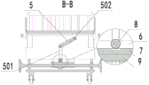
fig. 5 is a sectional view taken along line B-B of fig. 3 according to the present invention;
reference numerals are as follows: 1. a protective frame; 2. carrying a plate; 3. a sliding bed plate; 4. a drive assembly; 401. a sliding plate; 5. a linkage assembly; 501. rotating the rod; 502. a hinged lever; 6. mounting grooves; 7. a rack; 8. a gear; 9. a threaded rod; 10. a baffle plate; 11. a limiting member; 1101. mounting a plate; 1102. a connecting plate; 1103. a limiting groove; 1104. a sleeve; 1105. inserting a rod; 1106. a jack; 1107. a bump; 1108. against the spring.
Detailed Description
In order to make the objects, technical solutions and advantages of the embodiments of the present invention clearer, the drawings in the embodiments of the present invention are combined below to clearly and completely describe the technical solutions in the embodiments of the present invention.
As shown in fig. 1-5, a transfer bed for medical care comprises a movable frame body and a lifting member, wherein the lifting member is installed on the movable frame body, and the transfer bed further comprises:
the lifting part moving part of the two protection frames 1 is vertically upward and is symmetrically provided with two bearing plates 2, and the two protection frames 1 are respectively arranged at the tops of the two bearing plates 2; specifically, the lifting member is of a conventional structure, and in this embodiment, as shown in fig. 2, the lifting member is composed of an electric telescopic rod and a guiding telescopic rod, the guiding telescopic rod includes a guiding cylinder installed on the top of the movable frame, a guiding rod is vertically slidably installed inside the guiding cylinder, one end of the guiding rod is connected to one of the carrying plates 2, the electric telescopic rod is vertically installed on the movable frame, the movable end of the electric telescopic rod is connected to the other carrying plate 2,
the sliding bed plate 3 is horizontally and slidably arranged between the two bearing plates 2 and is used for bearing a patient, and the sliding direction of the sliding bed plate 3 faces the normal direction of one side of the length direction; that is, when the side of the operating table that the sliding bed board 3 moves, the height of the two protection frames 1 can be changed by the lifting piece, so that the bottom end of the sliding bed board 3 is flush with the operating table, at this time, the sliding bed board 3 is driven to move horizontally, so that the patient on the sliding bed board 3 is moved to the operating table, at this time, the part of the sliding bed board 3 is on the operating table surface, at this time, only the medical staff is needed to block one side of the patient, specifically, one side of the patient close to the movable frame body, at this time, the sliding bed board 3 moves, so that the sliding bed board 3 moves towards the direction of the movable frame body, at this time, because of the shielding of the hands of the medical staff, the sliding bed board 3 is drawn out from the lower part of the patient body, so that the sliding bed board 3 resets, when the operation of the patient is completed, the movable frame body can be moved to one side of the operating table, the bottom of the sliding bed board 3 faces the operating table through the lifting piece, the sliding bed board 3 is driven to move towards the operating table until contacting with a patient, at the moment, medical care personnel can lift the patient by a certain height to enable the sliding bed board 3 to move to the lower part of the patient and also enable the patient to turn over so as to enable the patient to lie on one side, then the sliding bed board 3 is moved to enable the sliding bed board 3 to contact with the back of the patient, then the medical care personnel turn over the patient again to enable the back of the patient to contact with the bottom of the sliding bed board 3 positioned on the operating table, so that the sliding bed board 3 is moved between the two protection frames 1 under the support of the medical care personnel, thereby completing the transfer of the patient, compared with the prior art, the device reduces the times of lifting the patient by the medical care personnel and does not need to pull the patient after lifting the patient, thereby reducing the labor capacity of the medical care personnel, the transportation is more convenient, thereby having more practicability,
drive assembly 4 installs between two loading boards 2, and acts on sliding bed board 3, that is to say, through drive assembly 4 so that sliding bed board 3 level to the removal to the realization shifts the patient that is located on sliding bed board 3.
As shown in fig. 2-4, in some embodiments, the driving assembly 4 includes a sliding plate 401 horizontally slidably installed between two bearing plates 2, an interlocking assembly 5 is installed between the sliding plate 401 and the sliding bed plate 3, when the sliding plate 401 moves, the sliding bed plate 3 moves through the interlocking assembly 5, a driving member for driving the sliding plate 401 to move is installed between the two bearing plates 2, that is, the sliding plate 401 moves through the driving member, the sliding bed plate 3 moves along with the sliding plate 401 through the interlocking assembly 5 during the moving process, so that part of the sliding bed plate 3 moves to the outside, specifically, protruding plates are configured on opposite sides of the two protection frames 1, through grooves are formed in tops of the protruding plates along the length direction of the protruding plates, and clamping bars attached to the through grooves are configured on the sliding bed plate 3, so as to perform guiding and limiting functions, preferably, universal balls are uniformly and rollably installed on the bottom surfaces inside the through grooves, and the clamping bars contact with the plurality of universal balls, so that the sliding bed plate 3 can be more smooth during moving.
As shown in fig. 2-5, in some embodiments, the linkage assembly 5 includes a rotating rod 501 with one end vertically installed between the two loading plates 2, the free end of the rotating rod 501 is hinged to a hinge rod 502, the free end of the hinge rod 502 is hinged to the bottom of the sliding bed board 3, when the sliding plate 401 moves, the linkage is used to rotate the rotating rod 501 around the rotation point with the loading plates 2, that is, when the sliding plate 401 moves, the rotating rod 501 can rotate through the linkage, so that the hinge rod 502 hinged to the rotating rod 501 rotates, because one end of the hinge rod 502 is hinged to the bottom of the sliding bed board 3, when the rotating rod 501 rotates, the sliding bed board 3 can be pulled or pushed by the hinge rod 502 to move horizontally, thereby realizing the movement of the sliding bed board 3.
As shown in fig. 2 to 5, in some embodiments, the top of the sliding plate 401 is provided with a mounting groove 6 along the length direction thereof, the linkage member includes a rack 7 installed in the mounting groove 6, one end of the rotating rod 501 is rotatably installed between the two loading plates 2 through a rotating shaft, and a gear 8 engaged with the rack 7 is installed on the rotating shaft, when the sliding plate 401 moves, the rack 7 installed in the mounting groove 6 moves due to the movement of the sliding plate 401, so that the gear 8 engaged with the rack 7 rotates, and since the gear 8 is installed on the rotating shaft, the rotating rod 501 rotates due to the rotation of the gear 8, so that the rotating rod 501 rotates around the hinge point with the loading plates 2, thereby achieving the rotation of the rotating rod 501.
As shown in fig. 2-5, in some embodiments, the driving member includes a threaded rod 9 horizontally and rotatably installed on the two bearing plates 2, the sliding plate 401 is threadedly sleeved on the threaded rod 9, it should be noted that the driving force of the threaded rod 9 may be motor-driven or manually-driven, different driving forces may be changed according to different hospitals, if motor-driven, the motor needs to be installed between the two bearing plates 2, the output shaft of the motor is connected to the threaded rod 9, and a battery needs to be installed on one of the bearing plates 2 to supply power to the motor, if the threaded rod 9 needs to be manually driven to rotate, a handwheel needs to be installed at the end portions of the two threaded rods 9, so as to facilitate the medical staff to rotate the threaded rod 9 (as shown in fig. 2), when the threaded rod 9 rotates, the sliding plate 401 can be moved by the threaded sleeve, thereby moving the rack 7 installed on the sliding plate 401, as shown in fig. 2, one side of the two bearing plates 2 is attached to both side walls of the bearing plate 6, thereby guiding the sliding plate 401 is guided, and preventing the sliding plate 401 from following the rotation of the sliding plate 9.
As shown in fig. 2 to 4, in some embodiments, opposite sides of the sliding bed plate 3 in the length direction are hinged to a baffle 10 through hinges, when the baffle 10 rotates, one side forming the baffle 10 is aligned with the bottom surface of the sliding bed plate 3, and a limiting member 11 for limiting the rotation of the baffle 10 is installed on the sliding bed plate 3, specifically, in a normal state, the baffle 10 is hinged to the sliding bed plate 3 by ninety degrees, and the rotation angle of the baffle 10 is limited through the limiting member 11, so as to prevent a patient from falling on the sliding plate 401 to the ground to cause injury to the human body, when the patient needs to be transported to a surgical table, the limiting of the baffle 10 can be released through the limiting member 11, so that the baffle 10 rotates to the horizontal state, so that the baffle 10 is aligned with the bottom surface of the sliding bed plate 3 through the limiting member 11, when the sliding bed plate 3 moves, the baffle 10 can play a role in supporting the sliding bed plate 3, and stability of the sliding bed plate 3 in moving is improved.
As shown in fig. 2 to 4, in some embodiments, the limiting member 11 includes a mounting plate 1101 horizontally configured on the sliding bed board 3, a connecting plate 1102 is vertically slidably mounted on the mounting plate 1101, a limiting groove 1103 for the connecting plate 1102 to be inserted into is formed at the bottom of the baffle plate 10, a sleeve 1104 is horizontally configured at one side of the connecting plate 1102, an insertion rod 1105 is horizontally slidably mounted inside the sleeve 1104, insertion holes 1106 for the insertion rod 1105 to be inserted into are vertically distributed on one side of the mounting plate 1101, a protrusion 1107 attached to an inner wall of the sleeve 1104 is configured on the insertion rod 1105, an interference spring 1108 is connected between the protrusion 1107 and the sleeve 1104, when the baffle plate 10 and the sliding bed board 3 are positioned at ninety degrees, the connecting plate 1102 is inserted into the limiting groove 1103, and the insertion rod 1105 is always positioned in the insertion hole 1106 due to an interference force of the interference spring 1108, so that when the mobile frame body is transported, the insertion rod 1105 is separated from the insertion hole 1106, when the baffle plate 10 needs to be rotated, the insertion rod 1105 can be separated from the upper interference spring 1106, then the connecting plate 1102 is moved downwards so that the connecting plate 1102 is separated from the limiting groove 1102, so that the insertion rod 1105 is positioned below the insertion hole 1105 can be rotated, and the elastic baffle plate 10 can be rotated, and the elastic position can be released.
The previous description of the disclosed embodiments is provided to enable any person skilled in the art to make or use the present invention. Various modifications to these embodiments will be readily apparent to those skilled in the art, and the generic principles defined herein may be applied to other embodiments without departing from the spirit or scope of the invention. Thus, the present invention is not intended to be limited to the embodiments shown herein but is to be accorded the widest scope consistent with the principles and novel features disclosed herein.
Claims (7)
1. The utility model provides a transportation bed that medical care used, includes portable support body and lifter, the lifter is installed on the portable support body, its characterized in that still includes:
the lifting piece comprises two protection frames (1), wherein two bearing plates (2) are vertically upwards arranged on the movable part of the lifting piece in a symmetrical mode, and the two protection frames (1) are respectively arranged at the tops of the two bearing plates (2);
the sliding bed board (3) is horizontally and slidably arranged between the two bearing plates (2) and is used for bearing a patient, and the sliding direction of the sliding bed board (3) faces the normal direction of one side of the length direction of the sliding bed board;
drive assembly (4), install between two loading boards (2), and act on sliding bed board (3), through drive assembly (4) are so that sliding bed board (3) level is to removing.
2. The transfer bed for medical care according to claim 1, wherein the driving assembly (4) comprises a sliding plate (401) horizontally slidably installed between the two carrying plates (2), a linkage assembly (5) is installed between the sliding plate (401) and the sliding bed plate (3), when the sliding plate (401) moves, the sliding bed plate (3) moves through the linkage assembly (5), and a driving member for driving the sliding plate (401) to move is installed between the two carrying plates (2).
3. The transfer bed for medical care according to claim 2, wherein the linkage assembly (5) comprises a rotating rod (501) with one end vertically and rotatably installed between the two loading plates (2), the free end of the rotating rod (501) is hinged with a hinge rod (502), the free end of the hinge rod (502) is hinged at the bottom of the sliding bed plate (3), and when the sliding plate (401) moves, the rotating rod (501) rotates around the rotating point with the loading plates (2) through a linkage.
4. The medical nursing transfer bed according to claim 3, wherein the top of the sliding plate (401) is provided with a mounting groove (6) along the length direction thereof, the linkage member comprises a rack (7) mounted in the mounting groove (6), one end of the rotating rod (501) is rotatably mounted between the two bearing plates (2) through a rotating shaft, and the rotating shaft is provided with a gear (8) engaged with the rack (7).
5. A transport bed for medical care according to claim 4, characterized in that the driving member comprises a threaded rod (9) mounted horizontally and rotatably on both of the carrying plates (2), and the sliding plate (401) is threaded onto the threaded rod (9).
6. The transfer bed for medical care according to claim 1, wherein the opposite sides of the sliding bed board (3) in the length direction are hinged with baffle plates (1) (0) through hinges, when the baffle plates (10) rotate, one side forming the baffle plates (10) is aligned with the bottom surface of the sliding bed board (3), and the sliding bed board (3) is provided with a limiting member (11) for limiting the rotation of the baffle plates (10).
7. The transfer bed of claim 6, wherein the limiting member (11) comprises a mounting plate (1101) horizontally configured on the slide bed plate (3), a connecting plate (1102) is vertically and slidably mounted on the mounting plate (1101), a limiting groove (1103) for the connecting plate (1102) to be inserted is formed in the bottom of the baffle plate (10), a sleeve (1104) is horizontally configured on one side of the connecting plate (1102), an inserting rod (1105) is horizontally and slidably mounted in the sleeve (1104), a jack (1106) for the inserting rod (1105) to be inserted is formed in one side of the mounting plate (1101) in an up-down distribution manner, a protruding block (1107) attached to the inner wall of the sleeve (1104) is configured on the inserting rod (1105), and a collision spring (1108) is connected between the protruding block (1107) and the sleeve (1104).
Priority Applications (1)
| Application Number | Priority Date | Filing Date | Title |
|---|---|---|---|
| CN202221884266.3U CN218607096U (en) | 2022-07-20 | 2022-07-20 | Transfer bed for medical care |
Applications Claiming Priority (1)
| Application Number | Priority Date | Filing Date | Title |
|---|---|---|---|
| CN202221884266.3U CN218607096U (en) | 2022-07-20 | 2022-07-20 | Transfer bed for medical care |
Publications (1)
| Publication Number | Publication Date |
|---|---|
| CN218607096U true CN218607096U (en) | 2023-03-14 |
Family
ID=85458025
Family Applications (1)
| Application Number | Title | Priority Date | Filing Date |
|---|---|---|---|
| CN202221884266.3U Active CN218607096U (en) | 2022-07-20 | 2022-07-20 | Transfer bed for medical care |
Country Status (1)
| Country | Link |
|---|---|
| CN (1) | CN218607096U (en) |
-
2022
- 2022-07-20 CN CN202221884266.3U patent/CN218607096U/en active Active
Similar Documents
| Publication | Publication Date | Title |
|---|---|---|
| CN107693265B (en) | Patient transfer device | |
| CN111631888B (en) | Internal medicine is convenient for remove patient's operating table with operation | |
| CN113288634A (en) | Postoperative clinical care is with supplementary device of getting up | |
| CN115363884A (en) | System is laid to external life support equipment | |
| CN215875267U (en) | Patient carrying bed | |
| CN218607096U (en) | Transfer bed for medical care | |
| CN213284901U (en) | Infusion support with adjustable thoracic surgery nursing is used | |
| CN213218315U (en) | Severe patient transfer device | |
| CN210170308U (en) | Transfer device for severe surgical patients | |
| CN111568651A (en) | Patient safety transfer device for intensive care therapy | |
| CN113317827A (en) | Spinal surgery is with leading out device | |
| CN210583271U (en) | Infusion support for oncology nursing | |
| CN212395222U (en) | Height-adjustable sliding type transfer trolley for passing bed | |
| CN112826671B (en) | Psychiatric department is with multi-functional medical vehicle | |
| CN214285461U (en) | Auxiliary device for patient of CT machine | |
| CN213724213U (en) | Anesthesia auxiliary stand for anesthesia | |
| CN109893374B (en) | Medical rotating bed robot | |
| CN209852363U (en) | Multifunctional health service vehicle | |
| CN215652240U (en) | Patient transfer equipment | |
| CN209847677U (en) | Medical rotary bed robot | |
| CN218792803U (en) | Transfer vehicle | |
| CN213218299U (en) | Multidirectional adjustable transfer bed | |
| CN215652297U (en) | Special instrument transfer trolley for nursing work | |
| CN215900114U (en) | Severe patient nurses with transporting frame | |
| CN217548402U (en) | Electric patient transfer bed |
Legal Events
| Date | Code | Title | Description |
|---|---|---|---|
| GR01 | Patent grant | ||
| GR01 | Patent grant |