CN218575627U - Hydraulic clamp for gear box machining - Google Patents
Hydraulic clamp for gear box machining Download PDFInfo
- Publication number
- CN218575627U CN218575627U CN202222671986.8U CN202222671986U CN218575627U CN 218575627 U CN218575627 U CN 218575627U CN 202222671986 U CN202222671986 U CN 202222671986U CN 218575627 U CN218575627 U CN 218575627U
- Authority
- CN
- China
- Prior art keywords
- closing device
- gear box
- machining
- pressing device
- frock
- Prior art date
- Legal status (The legal status is an assumption and is not a legal conclusion. Google has not performed a legal analysis and makes no representation as to the accuracy of the status listed.)
- Active
Links
Images


Classifications
-
- Y—GENERAL TAGGING OF NEW TECHNOLOGICAL DEVELOPMENTS; GENERAL TAGGING OF CROSS-SECTIONAL TECHNOLOGIES SPANNING OVER SEVERAL SECTIONS OF THE IPC; TECHNICAL SUBJECTS COVERED BY FORMER USPC CROSS-REFERENCE ART COLLECTIONS [XRACs] AND DIGESTS
- Y02—TECHNOLOGIES OR APPLICATIONS FOR MITIGATION OR ADAPTATION AGAINST CLIMATE CHANGE
- Y02E—REDUCTION OF GREENHOUSE GAS [GHG] EMISSIONS, RELATED TO ENERGY GENERATION, TRANSMISSION OR DISTRIBUTION
- Y02E10/00—Energy generation through renewable energy sources
- Y02E10/70—Wind energy
- Y02E10/72—Wind turbines with rotation axis in wind direction
Abstract
The utility model provides a hydraulic fixture for gear box processing, including the revolving stage, install the frock board on the revolving stage, revolving stage one end is provided with the oil distribution axle, the oil distribution axle is provided with a plurality of oil circuits in corresponding the frock board, install anchor clamps on the frock board; the fixture comprises a first pressing device, a limiting device, a second pressing device, a first profiling tool and a second profiling tool, wherein the second pressing device is installed on the tool plate in parallel with the first pressing device, the first profiling tool is installed in the middle of the first pressing device, the second pressing device is provided with two or two relative pressing devices, the second profiling tool is installed in the middle of the second pressing device, the limiting device is installed between the first pressing device and the second pressing device, and the limiting device corresponds to the tool plate and is provided with a through hole. The utility model discloses a clamping can be with the processing of gear box casing, and gear box casing machining precision is high, and is efficient.
Description
Technical Field
The utility model belongs to the technical field of the processing frock, especially, relate to a hydraulically operated fixture is used in gear box processing.
Background
The gearbox body belongs to a shell part, is relatively complex in structure, is Kong Duobi thin, is made of a material with high strength, wear resistance, heat resistance and vibration reduction performance, and is suitable for parts which bear large stress and require wear resistance. This places higher demands on the gearbox machining jig.
As shown in fig. 1 to 5, when a gearbox housing is machined on a machine tool, in order to ensure that the surface of the gearbox housing machined in the machining process can meet the technical requirements such as dimension and position accuracy specified on the drawing, a workpiece must occupy a correct machining position relative to a tool and the machine tool, and the gearbox housing must be tightly pressed and clamped, so that the machining position can be kept stable and unchanged when the gearbox housing is influenced by cutting force, centrifugal force, impact, vibration and the like in the machining process. However, the existing clamp has the following three disadvantages: 1. only a single-side structure of the gearbox shell can be processed, a hole on the opposite surface of the gearbox shell cannot be processed, and another set of clamp needs to be replaced, so that time is wasted, and the processing precision is also deficient; 2. the existing clamp clamping mode is manually clamped, and the clamping force is difficult to control, so that the machined gearbox shell often has poor dimension, deformation and the like; 3. the existing gearbox shell has low production efficiency and high labor intensity of workers; those skilled in the art are keen to solve such technical problems.
SUMMERY OF THE UTILITY MODEL
Not enough to the above-mentioned that prior art exists, the utility model provides a hydraulically operated fixture is used in gear box processing.
In order to achieve the above purpose, the utility model provides a following technical scheme:
a hydraulic clamp for machining a gear box comprises a rotary table, wherein a tooling plate is mounted on the rotary table and rotates 360 degrees along the rotary table, an oil distribution shaft is arranged at one end of the rotary table and corresponds to a plurality of oil ways arranged in the tooling plate, and a clamp is mounted on the tooling plate;
the fixture comprises a first pressing device, a limiting device, a second pressing device, a first profiling tool and a second profiling tool, wherein the second pressing device is mounted on the tooling plate in parallel with the first pressing device, the first pressing device is provided with two and two relatively, the first profiling tool is mounted in the middle of the first pressing device, the second pressing device is provided with two and two relatively, the second profiling tool is mounted in the middle of the second pressing device, the limiting device is mounted between the first pressing device and the second pressing device and is close to the first pressing device, the limiting device is provided with two and two relatively, a via hole is formed in the tooling plate corresponding to the limiting device, and the via hole is used for machining a back hole of a gear box shell.
Further, two clamps are arranged in parallel.
Furthermore, the first pressing device is provided with a first rotating oil cylinder, a first pressing block is hinged to the first rotating oil cylinder, and the first pressing block rotates along with the first rotating oil cylinder.
Furthermore, stop device is provided with the supporting shoe, the supporting shoe passes through the bolt fastening on the frock board, be provided with first ripples pearl screw on the supporting shoe, first ripples pearl screw towards first profile modeling frock sets up.
Further, the second closing device is provided with a base, the base is fixed on the tooling plate through bolts, a second rotary oil cylinder is installed on the base, a second pressing block is hinged to the second rotary oil cylinder and driven to rotate along with the second rotary oil cylinder, and the second pressing block and the first pressing block are used for fixing and limiting the gear box shell in the Z direction.
Further, a first profiling tool is provided with a first limiting seat, the first limiting seat is fixed on the tool plate through bolts, second wave bead screws are arranged on two opposite sides of the first limiting seat, a limiting block is installed on the first limiting seat, the limiting block is right opposite to the limiting device, and the limiting block and the limiting device are used for fixing and limiting the gear box shell.
Furthermore, the second profiling tool is provided with a second limiting seat, third wave bead screws are arranged on two opposite sides of the second limiting seat, and the third wave bead screws and the second wave bead screws are used for fixing and limiting the gearbox shell in the X direction.
Furthermore, the two first rotating oil cylinders and the second rotating oil cylinder are respectively connected with an oil circuit arranged in the tool plate through oil conveying pipes.
Has the advantages that: the utility model discloses a gear box processing hydraulic fixture, adopt profile modeling frock and ripples pearl screw to realize that X, Y of gear box casing is to fixed spacing, elasticity clamping, stability are strong, positioning accuracy is high; the Z-direction fixing and limiting of the gearbox shell are realized through the first pressing device and the second pressing device, the abrasion damage to the gearbox shell is small in the using process, the accurate pressing and fixing of the gearbox shell are realized, and the gearbox shell is matched with a machining tool to finish the machining process;
a through hole is formed between the two limiting devices and corresponds to the tooling plate, the tooling plate is rotated by 180 degrees through the rotary table, and a cutting tool extends into the through hole for machining a back hole of the gearbox shell; the gear box shell can be completely processed by one-time clamping, and the gear box shell is high in size processing precision and high in efficiency.
Drawings
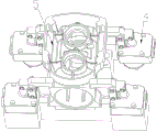
Fig. 1 is a schematic front structural view of a head housing of an angle grinder according to the background art of the present invention;
FIG. 2 is a schematic view of a back side structure of a head housing of an angle grinder according to the background art of the present invention;
FIG. 3 is a front view of a head housing of an angle grinder according to the background art of the present invention;
fig. 4 is a half sectional view of fig. 3 according to the present invention;
FIG. 5 is a top view of a head housing of an angle grinder according to the background of the present invention;
FIG. 6 is a schematic structural view of a hydraulic clamp for machining a gear box according to the present invention;
FIG. 7 is a schematic view of the fixture mounted to the gearbox housing according to the present invention;
fig. 8 is an installation schematic diagram of the first pressing device, the limiting device and the first profiling tool of the present invention;
fig. 9 is a schematic structural view of a second pressing device and a second profiling tool of the present invention;
fig. 10 is a top view of the clamp of the present invention;
fig. 11 is a left side view of the clamp of the present invention;
fig. 12 is a schematic structural view of the first pressing device of the present invention;
fig. 13 is a schematic structural view of the limiting device of the present invention;
fig. 14 is a schematic structural view of a second pressing device according to the present invention;
fig. 15 is a schematic structural view of a first profiling tool of the present invention;
fig. 16 is a schematic structural view of a second profiling tool of the present invention.
In the figure: 1 revolving stage, 2 frock boards, 3 join in marriage the oil spindle, 4 anchor clamps, the first closing device of 401, the first rotary cylinder of 4011, the first briquetting of 4012, 402 stop device, 4021 supporting shoe, the first ripples pearl screw of 4022, 403 second closing device, 4031 base, the second rotary cylinder of 4032, 4033 second briquetting, the first profile modeling frock of 404, the first spacing seat of 4041, the 4042 stopper, the second ripples pearl screw of 4043, 405 second profile modeling frock, the spacing seat of 4051 second, the third ripples pearl screw of 4052, 5 gearbox casings.
Detailed Description
The technical solutions in the embodiments of the present invention will be described clearly and completely with reference to the accompanying drawings in the embodiments of the present invention, and it is obvious that the described embodiments are only some embodiments of the present invention, not all embodiments. Based on the embodiments of the present invention, all other embodiments obtained by a person of ordinary skill in the art without creative efforts belong to the protection scope of the present invention.
As shown in fig. 6-11, the utility model provides a hydraulic fixture for gear box processing, including revolving stage 1, install frock board 2 on revolving stage 1, frock board 2 realizes 360 rotations along revolving stage 1, revolving stage 1 one end is provided with oil distribution shaft 3, oil distribution shaft 3 is provided with a plurality of oil circuits in corresponding frock board 2, install anchor clamps 4 on frock board 2;
the fixture 4 comprises a first pressing device 401, a limiting device 402, a second pressing device 403, a first profiling tool 404 and a second profiling tool 405, the second pressing device 403 is installed on the tooling plate 2 in parallel with the first pressing device 401, the first pressing device 401 is provided with two parts and two parts, the first profiling tool 404 is installed in the middle of the first pressing device 401, the second pressing device 403 is provided with two parts and two parts, the second profiling tool 405 is installed in the middle of the second pressing device 403, the limiting device 402 is installed between the first pressing device 401 and the second pressing device 403 and close to the first pressing device 401, the limiting device 402 is provided with two parts and two parts, a through hole 201 is formed in the corresponding tooling plate 2 between the limiting devices 402, and the through hole 201 is used for machining a back hole of the gearbox shell 5.
On the basis of the above embodiment, two clamps 4 are arranged in parallel, and the two clamps 4 improve the processing efficiency of the gearbox housing 5.
On the basis of the above embodiment, as shown in fig. 12, the first pressing device 401 is provided with a first rotating cylinder 4011, a first pressing block 4012 is hinged on the first rotating cylinder 4011, and the first pressing block 4012 is driven to rotate along with the first rotating cylinder 4011.
On the basis of the above embodiment, as shown in fig. 13, the limiting device 402 is provided with a supporting block 4021, the supporting block 4021 is fixed on the tooling plate 2 through a bolt, the supporting block 4021 is provided with a first wave ball screw 4022, the first wave ball screw 4022 is arranged facing the first profiling fixture 404, and the first wave ball screw 4022 is used for clamping the gear box housing 5 in a telescopic manner.
On the basis of the above embodiment, as shown in fig. 14, the second pressing device 403 is provided with a base 4031, the base 4031 is fixed on the tooling plate 2 through bolts, a second rotating cylinder 4032 is installed on the base 4031, a second pressing block 4033 is hinged to the second rotating cylinder 4032, the second pressing block 4033 is driven to rotate along with the second rotating cylinder 4032, and the second pressing block 4033 and the first pressing block 4012 are used for fixing and limiting the gear box housing 5 in the Z direction.
On the basis of the above embodiment, as shown in fig. 15, the first profiling fixture 404 is provided with a first limiting seat 4041, the first limiting seat 4041 is fixed on the tooling plate 2 through a bolt, the two opposite sides of the first limiting seat 4041 are provided with second wave bead screws 4043, a limiting block 4042 is installed on the first limiting seat 4041, the limiting block 4042 is just opposite to the limiting device 402, and the limiting block 4042 and the limiting device 402 are used for fixing and limiting the gear box housing 5 in the Y direction.
On the basis of the above embodiment, as shown in fig. 16, the second profiling fixture 405 is provided with a second limiting seat 4051, third ball screws 4052 are provided on two opposite sides of the second limiting seat 4051, and the third ball screws 4052 and the second ball screws 4043 are used for fixing and limiting the gear box housing 5 in the X direction.
On the basis of the above embodiments, the two first and second rotary cylinders 4011 and 4032 are respectively connected to the internal oil passages of the tooling plate 2 through oil pipes.
The specific working mode is as follows:
the utility model relates to a hydraulic fixture is used in gear box processing places gear box casing 5 on first profile modeling frock 404, second profile modeling frock 405, installs second ripples pearl screw 4043 on the first profile modeling frock 404, installs third ripples pearl screw 4052 on the second profile modeling frock 405, realizes gear box casing 5 through second ripples pearl screw 4043, third ripples pearl screw 4052 to fixed spacing;
a first wave bead screw 4022 is mounted on the limiting device 402, the first wave bead screw 4022 is arranged facing the first profiling tool 404, and the Y-direction fixing and limiting of the gearbox shell 5 are realized through a limiting block 4042 and the first wave bead screw 4022;
the Z-direction fixing and limiting of the gearbox shell 5 are realized through a first pressing device 401 and a second pressing device 403; a through hole 201 is formed between the two limiting devices 402 corresponding to the tooling plate 2, and the through hole 201 is used for machining a back hole of the gearbox shell 5; and after the processing is finished, the disassembly and the assembly are carried out manually.
The foregoing shows and describes the general principles, essential features and advantages of the present invention, with the understanding that the foregoing and following descriptions, as well as the appended drawings, are intended to illustrate and not limit the scope of the invention. It should be understood by those skilled in the art that the foregoing embodiments are merely illustrative of the technical concepts and features of the present invention, and the purpose of the present invention is to provide a person skilled in the art with the ability to understand the contents of the present invention and implement the same, and not to limit the scope of the present invention.
Claims (8)
1. The utility model provides a hydraulic fixture is used in gear box processing, includes revolving stage (1), its characterized in that: the rotary table (1) is provided with a tooling plate (2), the tooling plate (2) rotates 360 degrees along the rotary table (1), one end of the rotary table (1) is provided with an oil distribution shaft (3), a plurality of oil ways are arranged in the tooling plate (2) corresponding to the oil distribution shaft (3), and the tooling plate (2) is provided with a clamp (4);
anchor clamps (4) include first closing device (401), stop device (402), second closing device (403), first profile modeling frock (404), second profile modeling frock (405), second closing device (403) with first closing device (401) is installed side by side on frock board (2), first closing device (401) is provided with two relatively, two first profile modeling frock (404) is installed to the centre of first closing device (401), second closing device (403) is provided with two relatively, two second profile modeling frock (405) is installed to second closing device (403) centre, stop device (402) are installed between first closing device (401), second closing device (403), and be close to first closing device (401) set up, stop device (402) are provided with two relatively, two be provided with via hole (201) on corresponding frock board (2) between stop device (402), via hole (201) are used for the processing of gear box casing (5) back hole.
2. The hydraulic clamp for machining the gearbox according to claim 1, wherein: two clamps (4) are arranged in parallel.
3. The hydraulic clamp for machining the gearbox according to claim 1, wherein: first closing device (401) is provided with first rotatory hydro-cylinder (4011), it has first briquetting (4012) to articulate on first rotatory hydro-cylinder (4011), first briquetting (4012) are rotatory along with first rotatory hydro-cylinder (4011) drive.
4. The hydraulic clamp for machining the gearbox according to claim 1, wherein: the limiting device (402) is provided with a supporting block (4021), the supporting block (4021) is fixed on the tooling plate (2) through a bolt, a first wave ball screw (4022) is arranged on the supporting block (4021), and the first wave ball screw (4022) faces the first profiling tooling (404).
5. The hydraulic clamp for machining the gearbox according to claim 3, wherein the hydraulic clamp comprises: second closing device (403) is provided with base (4031), base (4031) is fixed through the bolt on frock board (2), install second swivel cylinder (4032) on base (4031), it has second briquetting (4033) to articulate on second swivel cylinder (4032), second briquetting (4033) is rotatory along with second swivel cylinder (4032) drive, second briquetting (4033), first briquetting (4012) are used for the Z of gear box casing (5) to fixed spacing.
6. The hydraulic clamp for machining the gearbox according to claim 4, wherein: first profile modeling frock (404) are provided with first spacing seat (4041), first spacing seat (4041) pass through the bolt fastening and are in on frock board (2), the relative both sides of first spacing seat (4041) are provided with second ripples pearl screw (4043), install stopper (4042) on first spacing seat (4041), stopper (4042) are just right stop device (402) set up, stopper (4042) with stop device (402) are used for the Y of gear box casing (5) to fixed spacing.
7. The hydraulic clamp for machining the gearbox according to claim 6, wherein: second profile modeling frock (405) is provided with spacing seat of second (4051), the relative both sides of spacing seat of second (4051) are provided with third ripples pearl screw (4052), second ripples pearl screw (4043) are used for the X of gear box casing (5) to fixed spacing.
8. The hydraulic clamp for machining the gearbox according to claim 5, wherein: the first rotating oil cylinder (4011) and the second rotating oil cylinder (4032) are respectively connected with oil passages in the tooling plate (2) through oil conveying pipes.
Priority Applications (1)
| Application Number | Priority Date | Filing Date | Title |
|---|---|---|---|
| CN202222671986.8U CN218575627U (en) | 2022-10-11 | 2022-10-11 | Hydraulic clamp for gear box machining |
Applications Claiming Priority (1)
| Application Number | Priority Date | Filing Date | Title |
|---|---|---|---|
| CN202222671986.8U CN218575627U (en) | 2022-10-11 | 2022-10-11 | Hydraulic clamp for gear box machining |
Publications (1)
| Publication Number | Publication Date |
|---|---|
| CN218575627U true CN218575627U (en) | 2023-03-07 |
Family
ID=85366379
Family Applications (1)
| Application Number | Title | Priority Date | Filing Date |
|---|---|---|---|
| CN202222671986.8U Active CN218575627U (en) | 2022-10-11 | 2022-10-11 | Hydraulic clamp for gear box machining |
Country Status (1)
| Country | Link |
|---|---|
| CN (1) | CN218575627U (en) |
-
2022
- 2022-10-11 CN CN202222671986.8U patent/CN218575627U/en active Active
Similar Documents
| Publication | Publication Date | Title |
|---|---|---|
| CN202668188U (en) | Double V-shaped block tooling used in milling of key slot of rotating shaft of motor | |
| CN201720571U (en) | Multi-start rotary frock used for electric spark processing | |
| CN218575627U (en) | Hydraulic clamp for gear box machining | |
| CN204471043U (en) | The quick interchangeable clamp mechanism of Digit Control Machine Tool | |
| CN201124254Y (en) | Drilling jig for processing electrohydraulic servo valve cover plate hole group | |
| CN202571830U (en) | Numerical control machine tool | |
| CN210255284U (en) | Four-axis rotating tool clamp | |
| CN205290443U (en) | A anchor clamps clamping platform for curved surface processing | |
| CN114799890B (en) | Turning and milling composite machining center | |
| CN114770379A (en) | Wheel hub automatically clamped machine of shifting towards robot grinds and throws | |
| CN110961696B (en) | Clamp for multi-angle drilling | |
| CN208696867U (en) | A kind of shaped piece processing assembled tool | |
| CN216576776U (en) | Fixture for machining elbow of machine tool | |
| CN220880676U (en) | A integrative milling cutter for moulding pipe cutting | |
| CN214237402U (en) | Grinding fixing device for alloy milling cutter blade | |
| CN214770427U (en) | Turning tool | |
| CN215092038U (en) | Deep hole bores with connection structure | |
| CN214291961U (en) | Numerical control turntable | |
| CN218874582U (en) | Full-automatic tool for machining angle grinder head shell | |
| CN211540256U (en) | Five processingequipment of double gear reduction gear for work piece production | |
| CN211565193U (en) | Drilling machine clamp for sheet metal part | |
| CN211516905U (en) | Five-axis machining device for large workpiece production | |
| CN216178670U (en) | Rotary modular tool for machining parts of container crane | |
| CN218476322U (en) | Vertical workbench of numerical control machining center | |
| CN220050853U (en) | Rotary accessory device for numerical control machine tool |
Legal Events
| Date | Code | Title | Description |
|---|---|---|---|
| GR01 | Patent grant | ||
| GR01 | Patent grant |