CN218535795U - Double-sheet synchronous vertical deviation-rectifying paper feeding equipment and carton stapler - Google Patents
Double-sheet synchronous vertical deviation-rectifying paper feeding equipment and carton stapler Download PDFInfo
- Publication number
- CN218535795U CN218535795U CN202222373028.2U CN202222373028U CN218535795U CN 218535795 U CN218535795 U CN 218535795U CN 202222373028 U CN202222373028 U CN 202222373028U CN 218535795 U CN218535795 U CN 218535795U
- Authority
- CN
- China
- Prior art keywords
- deviation
- conveying device
- conveying
- correcting
- assembly
- Prior art date
- Legal status (The legal status is an assumption and is not a legal conclusion. Google has not performed a legal analysis and makes no representation as to the accuracy of the status listed.)
- Active
Links
Images


Abstract
The utility model belongs to the technical field of the nail case equipment, specifically be a biplate is synchronous to rectify perpendicularly paper feed equipment and box press. The automatic deviation correction device comprises a rack, and a first deviation correction conveying device, a second deviation correction conveying device, a third deviation correction conveying device and a fourth deviation correction conveying device which are respectively installed on the rack in a sliding mode and are sequentially arranged in parallel from left to right, wherein the first deviation correction conveying device comprises an upper deviation correction conveying device and a lower deviation correction conveying device, and the upper deviation correction conveying device comprises an upper supporting plate installed on the rack in a sliding mode, an upper servo motor assembly fixedly installed on the upper supporting plate and an upper deviation correction conveying mechanism installed on the upper supporting plate; the lower deviation-correcting conveying device comprises a lower supporting plate, a lower servo motor assembly and a lower deviation-correcting conveying mechanism, wherein the lower supporting plate is arranged on the rack in a sliding mode, the lower servo motor assembly is fixedly arranged on the lower supporting plate, the lower deviation-correcting conveying mechanism is arranged on the lower supporting plate, and a corrugated board conveying channel is formed between the upper deviation-correcting conveying mechanism and the lower deviation-correcting conveying mechanism.
Description
Technical Field
The utility model belongs to the technical field of the nail case equipment, specifically be a biplate is synchronous to rectify perpendicularly paper feed equipment and box press.
Background
With the rapid development of the logistics industry in China, particularly the rise of the E-commerce industry, the rapid development of the express delivery industry is greatly promoted, the related packaging cartons are large in use amount under the background, and the packaging cartons are spread in various fields of modern society.
The invention discloses a double-sheet synchronous vertical deviation rectifying paper feeding device for a carton stapler, which is clearly shown in the patent with the prior application number of 202110709396.7 and the authorization publication number of CN113290933B, and the invention name of the patent is that the device is a double-sheet synchronous vertical deviation rectifying paper feeding device for the carton stapler, and is manufactured by the following steps: the first deviation-correcting conveying mechanism, the second deviation-correcting conveying mechanism, the third deviation-correcting conveying mechanism and the fourth deviation-correcting conveying mechanism are driven by the driving motor, the transmission assembly and the transmission shaft respectively, so that the whole machine equipment is large in weight, and meanwhile, the transmission precision is reduced through multi-stage transmission, and the deviation-correcting precision is influenced.
Based on this, the utility model discloses in, provide a novel biplate synchronous paper advance equipment of rectifying perpendicularly to overcome the defect in the background art.
SUMMERY OF THE UTILITY MODEL
An object of the utility model is to provide a biplate is synchronous to be rectified paper feed equipment perpendicularly, this equipment realize rectifying the transport operation by servo motor subassembly direct drive conveying mechanism transmission of rectifying, shaftless transmission, the noise is little, convenient maintenance, simultaneously, has alleviateed the whole weight of complete machine equipment, improves whole transmission precision, improves the precision of rectifying.
The utility model adopts the following technical scheme: a double-sheet synchronous vertical deviation rectifying paper feeding device comprises a rack, a first deviation rectifying conveying device, a second deviation rectifying conveying device, a third deviation rectifying conveying device and a fourth deviation rectifying conveying device which are respectively installed on the rack in a sliding mode and are sequentially arranged in parallel from left to right, wherein the first deviation rectifying conveying device, the second deviation rectifying conveying device, the third deviation rectifying conveying device and the fourth deviation rectifying conveying device are of the same structure;
the first deviation-rectifying conveying device comprises an upper deviation-rectifying conveying device and a lower deviation-rectifying conveying device, the upper deviation-rectifying conveying device comprises an upper supporting plate which is slidably mounted on the rack, an upper servo motor assembly which is fixedly mounted on the upper supporting plate, and an upper deviation-rectifying conveying mechanism which is mounted on the upper supporting plate, and the upper servo motor assembly is connected with the upper deviation-rectifying conveying mechanism;
the lower deviation-rectifying conveying device comprises a lower supporting plate which is slidably mounted on the rack, a lower servo motor assembly which is fixedly mounted on the lower supporting plate, and a lower deviation-rectifying conveying mechanism which is mounted on the lower supporting plate, wherein the lower servo motor assembly is connected with the lower deviation-rectifying conveying mechanism, and a corrugated board conveying channel is formed between the upper deviation-rectifying conveying mechanism and the lower deviation-rectifying conveying mechanism;
the upper servo motor assembly and the lower servo motor assembly are integrated machines integrating a servo motor and a speed reducer.
Further, the upper deviation-rectifying conveying device is in transmission connection with the rack through a lifting adjusting mechanism;
the lifting adjusting mechanism comprises a lifting power motor, a worm and gear assembly and a lifting frame; the lifting power motor is arranged on the rack and is in transmission connection with a worm wheel of the worm and gear assembly; the worm gear assembly is arranged on the inner side of the rack, the worm tail end of the worm gear assembly is connected with the lifting frame, the upper deviation correcting conveying device is installed on the lifting frame, and the lifting frame is driven by the worm gear assembly to vertically move up and down so as to adjust a gap between the upper deviation correcting conveying device and the lower deviation correcting conveying device.
Furthermore, the upper deviation-correcting conveying device and the lower deviation-correcting conveying device are arranged on the rack and the lifting frame through a synchronous sliding mechanism, and the synchronous sliding mechanism further comprises a transverse moving driving motor, a chain transmission assembly and a lead screw sliding assembly;
the rack is provided with a transverse moving driving motor, the rack and the lifting frame are respectively provided with a plurality of groups of screw rod sliding assemblies which are arranged in parallel, the transverse moving driving motor is in transmission connection with screw rods in the screw rod sliding assemblies through chain transmission assemblies, and nuts in the screw rod sliding assemblies are respectively and correspondingly fixedly connected with an upper supporting plate of the upper deviation correcting conveying device and a lower supporting plate of the lower deviation correcting conveying mechanism so as to drive the upper deviation correcting conveying device and the lower deviation correcting conveying device to move towards or away from the center of the rack synchronously.
Furthermore, the upper deviation-rectifying conveying mechanism comprises an upper conveying belt assembly and a pressure adjusting assembly which are arranged on the upper supporting plate, and the pressure adjusting assembly is positioned between an upper belt and a lower belt of the upper conveying belt assembly;
the pressure adjusting component comprises a supporting shaft vertically arranged on the upper supporting plate, a torsion spring and a swinging sleeve sleeved on the supporting shaft, and a balance wheel connected with the swinging sleeve; one end of the torsion spring is connected with the supporting shaft, and the other end of the torsion spring is connected with the swinging sleeve; the bottom of the swinging sleeve extends downwards to form a stopping part, a limiting part matched with the stopping part is arranged on the inner side of the upper supporting plate, and the limiting part limits the pressure exerted on the lower belt of the upper conveying belt assembly by the swinging wheel.
Further, the upper deviation-correcting conveying mechanism comprises an upper conveying belt assembly, and the lower deviation-correcting conveying mechanism comprises a lower conveying belt assembly; a first corrugated board conveying channel is formed between the upper conveying belt assembly and the lower conveying belt assembly of the first deviation-correcting conveying device and the second deviation-correcting conveying device; a second corrugated board conveying channel is formed between the upper conveying belt assembly and the lower conveying belt assembly of the third deviation-correcting conveying device and the fourth deviation-correcting conveying device, and the first corrugated board conveying channel and the second corrugated board conveying channel have a height difference.
Furthermore, strip-shaped adjusting grooves extending towards the paper outlet direction are formed in the paper outlet ends of the upper supporting plate and the lower supporting plate, and the tail end tensioning wheels on the upper conveying belt assembly and the lower conveying belt assembly can move back and forth in the strip-shaped adjusting grooves to adjust the belt tensioning degrees of the upper conveying belt assembly and the lower conveying belt assembly.
Furthermore, a nailing device is arranged between the second deviation rectifying and conveying device and the third deviation rectifying and conveying device and is positioned at the paper outlet end.
Compared with the prior art, the beneficial effects of the utility model are that:
the utility model discloses well biplate is synchronous to rectify perpendicularly paper advance equipment comprises the deviation correcting device that first deviation correcting conveyor, second deviation correcting conveyor, third deviation correcting conveyor and fourth deviation correcting conveyor four groups were parallel and the interval set up, realizes the transport of rectifying when two corrugated container boards.
Meanwhile, the deviation-rectifying conveying device comprises a corresponding supporting plate, a servo motor assembly fixedly mounted on the supporting plate and a deviation-rectifying conveying mechanism, the deviation-rectifying conveying mechanism is directly driven by the servo motor assembly to transmit, deviation-rectifying conveying operation is achieved, the design of a transmission shaft and other transmission assemblies is reduced, shaftless transmission is achieved, noise is low, maintenance is convenient, meanwhile, the overall weight of the whole machine equipment is reduced, the overall transmission precision is improved, and the deviation-rectifying precision is improved.
Another object of the utility model is to provide a carton stapler, it includes foretell biplate synchronous paper feed equipment of rectifying perpendicularly.
Drawings
For a clearer explanation of the embodiments of the present invention or the technical solutions in the prior art, the drawings used in the description of the embodiments or the prior art will be briefly described below, it is obvious that the drawings in the following description are only some embodiments of the present invention, and for those skilled in the art, other drawings can be obtained according to these drawings without creative efforts.
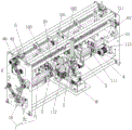
FIG. 1 is the overall structure diagram of the double-sheet synchronous vertical deviation rectifying paper feeding apparatus of the present invention;
FIG. 2 is a schematic view of the structure of FIG. 1 with some parts removed;
FIG. 3 is a schematic structural view of the pressure adjustment assembly of FIG. 1;
FIG. 4 is a schematic structural view of the nailing device of FIG. 1;
wherein: the device comprises a first deviation-rectifying conveying device 1, an upper deviation-rectifying conveying device 10, an upper supporting plate 101, a strip-shaped adjusting groove 1011, a limiting piece 1012, an upper servo motor assembly 102, an upper deviation-rectifying conveying mechanism 103, a lower deviation-rectifying conveying device 11, a lower supporting plate 111, a lower servo motor assembly 112, a lower deviation-rectifying conveying mechanism 113, a lower conveying belt assembly 12, a pressure adjusting assembly 13, a supporting shaft 131, a stopping portion 1331, a torsion spring 132, a swinging sleeve 133, a balance 134 and an upper conveying belt assembly 14; a second deviation rectifying and conveying device 2; a third deviation rectifying and conveying device 3; a fourth deviation correcting conveyor 4; a frame 5; the lifting adjusting mechanism 6, a lifting power motor 60, a worm and gear assembly 61 and a lifting frame 62; the synchronous sliding mechanism 7, the transverse moving driving motor 70, the lead screw sliding assembly 71, the lead screw 711 and the chain transmission assembly 72; the nailing device 8, the nose base 81, the nose eccentric lifting device 82, the roller component 83, the nose wall board 84, the left nose wall board 840, the right nose wall board 841, the power device 85, the nail box nose device 86, the transmission component 860, the nail box nose execution component 861 and the wire feeding component 862.
Detailed Description
The technical solutions in the embodiments of the present invention will be described clearly and completely with reference to the accompanying drawings in the present application, and it is obvious that the described embodiments are only some embodiments of the present invention, not all embodiments. Based on the embodiments of the present invention, all other embodiments obtained by a person skilled in the art without creative efforts belong to the protection scope of the present invention.
As shown in fig. 1-4, the utility model provides a biplate is synchronous to be rectified paper advance equipment perpendicularly for nail case field, it includes frame 5, respectively slidable mounting in parallel arrangement's first conveyor 1, second deviation correcting conveyor 2, third deviation correcting conveyor 3 and fourth deviation correcting conveyor 4 from left to right in proper order in frame 5, first conveyor 1, second deviation correcting conveyor 2, third deviation correcting conveyor 3 and fourth deviation correcting conveyor 4 adopt the same structure.
The following describes specific structures of the first deviation rectification conveying device 1, the second deviation rectification conveying device 2, the third deviation rectification conveying device 3 and the fourth deviation rectification conveying device 4 by taking the first deviation rectification conveying device 1 as an example.
Wherein, first deviation correcting conveyor 1 includes deviation correcting conveyor 10 and lower deviation correcting conveyor 11, on deviation correcting conveyor 10 includes slidable mounting last backup pad 101, fixed mounting in frame 5 go up last servo motor subassembly 102 on backup pad 101 and install last deviation correcting conveyor 103 on the last backup pad 101, go up servo motor subassembly 102 with last deviation correcting conveyor 103 is connected, the drive is gone up deviation correcting conveyor 103 and is moved. The lower deviation-rectifying conveying device 11 comprises a lower supporting plate 111 slidably mounted on the frame 5, a lower servo motor assembly 112 fixedly mounted on the lower supporting plate 111, and a lower deviation-rectifying conveying mechanism 113 mounted on the lower supporting plate 111, wherein the lower servo motor assembly 112 is connected with the lower deviation-rectifying conveying mechanism 113 to drive the lower deviation-rectifying conveying mechanism 113 to act, and a corrugated board conveying channel is formed between the upper deviation-rectifying conveying mechanism 103 and the lower deviation-rectifying conveying mechanism 113 and used for conveying corrugated boards. The upper servo motor assembly 102 and the lower servo motor assembly 112 are all integrated machines integrating a servo motor and a speed reducer.
The utility model discloses well biplate is synchronous to rectify perpendicularly paper advance equipment comprises the deviation correcting device that first deviation correcting conveyor 1, second deviation correcting conveyor 2, third deviation correcting conveyor 3 and fourth deviation correcting conveyor 4 four groups parallel and the interval set up, realizes the transport of rectifying when two corrugated container board. Meanwhile, the deviation-rectifying conveying device comprises a corresponding supporting plate, a servo motor assembly fixedly mounted on the supporting plate and a deviation-rectifying conveying mechanism, the deviation-rectifying conveying mechanism is directly driven by the servo motor assembly to transmit, deviation-rectifying conveying operation is achieved, the design of a transmission shaft and other transmission assemblies is reduced, shaftless transmission is achieved, noise is low, the whole machine is simple, flexible and attractive, maintenance is convenient, meanwhile, the whole weight of the whole machine is reduced, the whole transmission precision is improved, and the deviation-rectifying precision is improved.
Further, in order to adapt to the operation of rectifying a deviation of different thickness corrugated container board, the utility model discloses in with go up rectifying a deviation conveyor 10 design become can be vertical adjust from top to bottom to adjust on rectifying a deviation conveyor 10 and the interval between 11 lower rectifying a deviation conveyor. In this embodiment, the following technical scheme is adopted, and the upper deviation-correcting conveying device 10 is in transmission connection with the frame 5 through the lifting adjusting mechanism 6 so as to adjust the gap between the upper deviation-correcting conveying device 10 and the lower deviation-correcting conveying device 11, and further adjust the gap and the pressure between the lower belt of the upper deviation-correcting conveying device 10 and the upper belt of the lower deviation-correcting conveying device 11, so that the gap value can be adjusted according to the thickness of the conveyed corrugated paper plate, and the thickness of different corrugated papers can be adapted.
The lifting adjusting mechanism 6 comprises a lifting power motor 60, a worm and gear assembly 61 and a lifting frame 62, wherein the lifting power motor 60 is arranged on the rack 5 and is in transmission connection with a worm wheel of the worm and gear assembly 61; the worm and gear assembly 61 is arranged on the inner side of the rack 1, the tail end of a worm of the worm and gear assembly 61 is connected with the top end of the lifting frame 62, and the upper deviation-correcting conveying mechanism 103 is arranged on the lifting frame 62; the worm gear assembly 61 drives the lifting frame 62 to vertically move up and down so as to adjust the gap between the upper deviation-correcting conveying device 10 and the lower deviation-correcting conveying device 11. When the automatic lifting device works, the lifting power motor 60 drives the worm gear assembly 61 to drive the lifting frame 62 and the upper deviation correcting conveying device 10 to lift, so that the gap between the upper deviation correcting conveying device 10 and the lower deviation correcting conveying device 11 is adjusted. Specifically, in the present embodiment, the worm and gear assembly 61 includes a worm wheel and a worm, and the worm and gear assembly is in transmission connection with the worm wheel and the worm. Meanwhile, in the embodiment, the worm and gear assemblies 61 are arranged in two groups and are respectively arranged on the left side and the right side of the rack 1, and the two worm gears are connected through a connecting rod to realize synchronous motion; the tail ends of the two worms are respectively hinged with the left side and the right side of the lifting frame 62, and the lifting frame 62 is lifted by two points to control lifting, so that the stability is enhanced.
Further, in order to adapt to the operation of rectifying a deviation of different width corrugated container board, the utility model discloses but in with this go up rectifying conveyor 10 design into synchronous lateral slipping for can adjust first rectifying conveyor 1, second rectifying conveyor 2, the third rectifying conveyor 3, the fourth rectifying conveyor 4 in adjacent two according to corrugated container board's width and go up the interval between the rectifying conveyor 10. In this embodiment, the following technical solution is adopted, and the upper deviation-correcting conveyor 10 and the lower deviation-correcting conveyor 11 are installed on the frame 5 and the lifting frame 62 through the synchronous sliding mechanism 7. Correspondingly, the synchronous sliding mechanism 7 comprises a transverse moving driving motor 70, a chain transmission assembly 72 and a lead screw sliding assembly 71, the rack 5 is provided with the transverse moving driving motor 70, the crane 62 and the rack 5 are respectively provided with a plurality of groups of lead screw sliding assemblies 71 which are arranged in parallel, the transverse moving driving motor 70 is in transmission connection with a lead screw 711 in the lead screw sliding assembly 71 through the chain transmission assembly 72, and nuts in the lead screw sliding assemblies 71 are respectively and correspondingly fixedly connected with an upper supporting plate 101 and a lower supporting plate 111 so as to drive the upper deviation-correcting conveying device 10 and the lower deviation-correcting conveying device 11 to synchronously move towards or away from the center of the rack 5, thereby realizing synchronous sliding of the upper deviation-correcting conveying device 10 and the lower deviation-correcting conveying device 11. In this embodiment, four sets of lead screw sliding assemblies 71 are provided, two sets of lead screw sliding assemblies 71 are provided on the lifting frame 62 and are in transmission connection with the upper support plate 101 of the upper deviation-correcting conveying device 10, and the other two sets of lead screw sliding assemblies are provided on the rack 5 and are in transmission connection with the lower support plate 111 of the lower deviation-correcting conveying device 11, so that multi-point support is realized, and the sliding stability is good. It should be noted that, because a part of the screw sliding assemblies 71 are installed on the lifting frame 62, the lifting frame 62 can be lifted up and down along with the lifting adjusting mechanism 6, so that the distance between the corresponding screws can be changed, flexible adjustment of the chain in the chain transmission assembly 72 needs to be realized, the chain is always kept in a tensioning state, and the corresponding realization mode can be designed by a person skilled in the art according to actual conditions, and is not described herein again.
Further, the upper deviation-correcting conveying mechanism 103 comprises a lower upper conveying belt component 14 and a pressure adjusting component 13 which are installed on the upper supporting plate 101, and the pressure adjusting component 13 is located between an upper belt and a lower belt of the upper conveying belt component 14 and used for finely adjusting the pressure between the belts and the corrugated board;
the pressure adjusting assembly 13 includes a supporting shaft 131 vertically installed on the upper supporting plate 101, a torsion spring 132 and a swinging sleeve 133 sleeved on the supporting shaft 131, and a balance 134 connected to the swinging sleeve 133. One end of the torsion spring 132 is connected with the support shaft 131, and the other end is connected with the swing sleeve 133; the bottom of the swinging sleeve 133 extends downwards to form a stop portion 1331, a limiting member 1012 matched with the stop portion 1331 is arranged on the inner side of the upper support plate 101, and the limiting member 1012 limits the pressure applied by the balance 134 on the lower belt of the upper conveying belt assembly 14, so that the upper deviation-correcting conveying mechanism 103 can be adjusted finely according to the thickness deviation of the paper board, and the pressure of the belt on the paper board is ensured.
Further, the upper deviation correcting conveying mechanism 103 comprises an upper conveying belt assembly 14, and the lower deviation correcting conveying mechanism 113 comprises a lower conveying belt assembly 12; a first corrugated board conveying channel is formed between the upper conveying belt assembly and the lower conveying belt assembly of the first deviation-correcting conveying device 1 and the second deviation-correcting conveying device 2, and the first corrugated board conveying channel is used for conveying a first piece of corrugated paper; a second corrugated board conveying channel is formed between the upper conveying belt assembly and the lower conveying belt assembly of the third deviation-rectifying conveying device 3 and the fourth deviation-rectifying conveying device 4, and the second corrugated board conveying channel is used for conveying a second piece of corrugated paper; the first corrugated paper board conveying channel and the second corrugated paper board conveying channel have a height difference and are used for ensuring a gap between two pieces of corrugated paper which are overlapped.
Further, strip-shaped adjusting grooves 1011 extending towards the paper discharging direction are formed in the paper discharging ends of the upper supporting plate 101 and the lower supporting plate 111, and the tail end tensioning wheels on the upper conveying belt assembly 14 and the lower conveying belt assembly 12 can move back and forth in the strip-shaped adjusting grooves 1011 to adjust the belt tensioning degrees of the upper conveying belt assembly 14 and the lower conveying belt assembly 12.
Further, be equipped with nailing device 8 between second conveyor 2 and the third conveyor 3 of rectifying, nailing device 8 is located exit slot department, and nailing device 8 is used for carrying out the nailing to two corrugated papers of rectifying the completion.
The nailing device 8 comprises a machine head base 81, wherein a machine head eccentric lifting device 82 is arranged in the machine head base 81, the machine head eccentric lifting device 82 is used for adjusting the height of the whole nailing box machine head, and roller assemblies 83 are respectively arranged at four corners of the bottom of the machine head base 81;
the nose wallboard 84 is mounted on the nose eccentric lifting device 82, the nose wallboard 84 comprises a left nose wallboard 840 and a right nose wallboard 841, and the left nose wallboard 840 and the right nose wallboard 841 are oppositely arranged and are used for supporting a nail box nose device 86, a power device 85 and the like on a nail box nose; in this embodiment, the left handpiece wallboard 840 and the right handpiece wallboard 841 are both L-shaped;
the power device 85 is used for providing power for the action of the nail box machine head, and is fixedly arranged on the outer side of the left machine head wallboard 840 or the right machine head wallboard 841;
the box nailing machine head device 86 is mounted on the machine head wall plate 84 and connected with the power device 85, and the box nailing machine head device 86 acts under the driving of the power device 85 to realize box nailing operation and the like.
When the nail box machine head device works, the power device 85 drives the nail box machine head device 86 to act, and the nail box operation is realized. The eccentric nose lifting device 82 is arranged in the nose base 81, so that the lifting adjustment of the nose of the nail box can be realized, and the position of the nose of the nail box can be adjusted according to actual conditions. Meanwhile, four groups of roller assemblies 83 are arranged at the bottom of the head base 81, so that the operation of installation, debugging, maintenance and the like after the whole nail box head is moved out is facilitated, and the labor and material cost of an enterprise is saved. In addition, the machine head base 81 and the machine head wallboard 84 are arranged in a split mode, so that the whole machine equipment is more compact, and the size of the whole machine equipment is reduced.
Wherein the magazine head assembly 86 comprises:
a transmission assembly 860, wherein the transmission assembly 860 is installed on the handpiece wall board 84, and the input end of the transmission assembly 860 is connected with the power device 85;
the box nailing machine head executing assembly 861 is connected with the output end of the transmission assembly 860, and the power device 85 transmits power to the box nailing machine head executing assembly 861 through the transmission assembly 860 to drive the box nailing machine head executing assembly 861 to swing back and forth so as to realize box nailing motion;
the wire feeding component 862 is fixedly arranged on the front side of the bottom of the nose wallboard 84, so that the maintenance of the wire feeding component 862 after the nail box nose is removed is facilitated; the input end of the wire feeding component 862 is in transmission connection with the power device 85, and the output end of the wire feeding component 862 is connected with the nail box machine head executing component 861, so as to synchronously provide materials for the nail box machine head executing component 861 for nail box operation.
In operation, the power device 85 is started, the wire feeding assembly 862 is driven to provide materials for the nail box machine head executing assembly 861 for nail box operation, the transmission assembly 860 is synchronously driven, power is transmitted to the nail box machine head executing assembly 861, and the nail box operation is executed. Correspondingly, the utility model discloses in, do not injecing nail case aircraft nose executive component 861 and drive assembly 860's concrete structure, as long as can realize the transmission with the nail case function can, can refer to the prior art design, the utility model discloses in do not specifically injecing. In a similar way, corresponding, send a subassembly 862 can be shown as this embodiment, adopt bevel gear group + to send the combined design of a gear, realize sending the process of silk, for nail case aircraft nose execute subassembly 861 provides the material, also can refer to prior art design, the utility model discloses in do not specifically limit.
The utility model discloses still on the synchronous paper feed equipment basis of rectifying perpendicularly of above-mentioned biplate, developed a box press, including foretell biplate synchronous paper feed equipment of rectifying perpendicularly, have biplate synchronous all advantages of paper feed equipment of rectifying perpendicularly, here is no longer described any more.
The present invention has been further described with reference to the specific embodiments, but it should be understood that the specific description should not be construed as limiting the spirit and scope of the invention, and various modifications made to the above embodiments by those skilled in the art after reading the present specification are within the scope of the invention.
Claims (8)
1. The utility model provides a biplate is synchronous paper feed equipment of rectifying perpendicularly which characterized in that:
the automatic correction device comprises a rack, and a first correction conveying device, a second correction conveying device, a third correction conveying device and a fourth correction conveying device which are respectively installed on the rack in a sliding mode and are sequentially arranged in parallel from left to right, wherein the first correction conveying device, the second correction conveying device, the third correction conveying device and the fourth correction conveying device adopt the same structure;
the first deviation-rectifying conveying device comprises an upper deviation-rectifying conveying device and a lower deviation-rectifying conveying device, the upper deviation-rectifying conveying device comprises an upper supporting plate which is slidably mounted on the rack, an upper servo motor assembly which is fixedly mounted on the upper supporting plate, and an upper deviation-rectifying conveying mechanism which is mounted on the upper supporting plate, and the upper servo motor assembly is connected with the upper deviation-rectifying conveying mechanism;
the lower deviation-correcting conveying device comprises a lower supporting plate, a lower servo motor assembly and a lower deviation-correcting conveying mechanism, wherein the lower supporting plate is slidably mounted on the rack, the lower servo motor assembly is fixedly mounted on the lower supporting plate, the lower deviation-correcting conveying mechanism is mounted on the lower supporting plate, the lower servo motor assembly is connected with the lower deviation-correcting conveying mechanism, and a corrugated board conveying channel is formed between the upper deviation-correcting conveying mechanism and the lower deviation-correcting conveying mechanism;
the upper servo motor assembly and the lower servo motor assembly are integrated machines integrating a servo motor and a speed reducer.
2. The double-sheet synchronous vertical deviation rectification paper feeding equipment as claimed in claim 1, characterized in that:
the upper deviation-rectifying conveying device is in transmission connection with the rack through a lifting adjusting mechanism;
the lifting adjusting mechanism comprises a lifting power motor, a worm and gear assembly and a lifting frame; the lifting power motor is arranged on the rack and is in transmission connection with a worm wheel of the worm and gear assembly; the worm gear assembly is arranged on the inner side of the rack, the worm tail end of the worm gear assembly is connected with the lifting frame, the upper deviation correcting conveying device is installed on the lifting frame, and the lifting frame is driven by the worm gear assembly to vertically move up and down so as to adjust a gap between the upper deviation correcting conveying device and the lower deviation correcting conveying device.
3. The double-sheet synchronous vertical deviation rectifying paper feeding equipment according to claim 2, characterized in that:
the upper deviation-correcting conveying device and the lower deviation-correcting conveying device are arranged on the rack and the lifting frame through a synchronous sliding mechanism, and the synchronous sliding mechanism further comprises a transverse moving driving motor, a chain transmission assembly and a lead screw sliding assembly;
the transverse moving driving motor is connected with a lead screw in the lead screw sliding assembly in a transmission manner through a chain transmission assembly, and nuts in the lead screw sliding assembly are respectively and correspondingly fixedly connected with an upper supporting plate of the upper deviation-correcting conveying device and a lower supporting plate of the lower deviation-correcting conveying mechanism so as to drive the upper deviation-correcting conveying device and the lower deviation-correcting conveying device to move close to or far away from the center of the rack synchronously.
4. The double-sheet synchronous vertical deviation rectifying paper feeding equipment according to claim 1, characterized in that:
the upper deviation-rectifying conveying mechanism comprises an upper conveying belt assembly and a pressure adjusting assembly which are arranged on the upper supporting plate, and the pressure adjusting assembly is positioned between an upper belt and a lower belt of the upper conveying belt assembly;
the pressure adjusting component comprises a supporting shaft vertically arranged on the upper supporting plate, a torsion spring and a swinging sleeve sleeved on the supporting shaft, and a balance wheel connected with the swinging sleeve; one end of the torsion spring is connected with the supporting shaft, and the other end of the torsion spring is connected with the swinging sleeve; the bottom of the swinging sleeve extends downwards to form a stopping part, a limiting part matched with the stopping part is arranged on the inner side of the upper supporting plate, and the limiting part limits the pressure exerted by the balance wheel on the lower belt of the upper conveying belt assembly.
5. The double-sheet synchronous vertical deviation rectifying paper feeding equipment according to claim 1, characterized in that:
the upper deviation-correcting conveying mechanism comprises an upper conveying belt assembly, and the lower deviation-correcting conveying mechanism comprises a lower conveying belt assembly; a first corrugated board conveying channel is formed between the upper conveying belt assembly and the lower conveying belt assembly of the first deviation-correcting conveying device and the second deviation-correcting conveying device; a second corrugated board conveying channel is formed between the upper conveying belt assembly and the lower conveying belt assembly of the third deviation-correcting conveying device and the fourth deviation-correcting conveying device, and the first corrugated board conveying channel and the second corrugated board conveying channel have a height difference.
6. The double-sheet synchronous vertical deviation rectifying paper feeding equipment according to claim 5, characterized in that:
the strip-shaped adjusting grooves extending towards the paper outlet direction are formed in the paper outlet ends of the upper supporting plate and the lower supporting plate, and the tail end tensioning wheels on the upper conveying belt assembly and the lower conveying belt assembly can move back and forth in the strip-shaped adjusting grooves to adjust the belt tensioning degree of the upper conveying belt assembly and the lower conveying belt assembly.
7. The double-sheet synchronous vertical deviation rectification paper feeding equipment as claimed in claim 1, characterized in that:
and a nailing device is arranged between the second deviation rectifying and conveying device and the third deviation rectifying and conveying device and is positioned at the paper outlet end.
8. A carton stapler is characterized in that: comprising a two-sheet synchronous vertical offset correction paper advance apparatus as claimed in any one of claims 1 to 7.
Priority Applications (1)
| Application Number | Priority Date | Filing Date | Title |
|---|---|---|---|
| CN202222373028.2U CN218535795U (en) | 2022-09-07 | 2022-09-07 | Double-sheet synchronous vertical deviation-rectifying paper feeding equipment and carton stapler |
Applications Claiming Priority (1)
| Application Number | Priority Date | Filing Date | Title |
|---|---|---|---|
| CN202222373028.2U CN218535795U (en) | 2022-09-07 | 2022-09-07 | Double-sheet synchronous vertical deviation-rectifying paper feeding equipment and carton stapler |
Publications (1)
| Publication Number | Publication Date |
|---|---|
| CN218535795U true CN218535795U (en) | 2023-02-28 |
Family
ID=85272332
Family Applications (1)
| Application Number | Title | Priority Date | Filing Date |
|---|---|---|---|
| CN202222373028.2U Active CN218535795U (en) | 2022-09-07 | 2022-09-07 | Double-sheet synchronous vertical deviation-rectifying paper feeding equipment and carton stapler |
Country Status (1)
| Country | Link |
|---|---|
| CN (1) | CN218535795U (en) |
-
2022
- 2022-09-07 CN CN202222373028.2U patent/CN218535795U/en active Active
Similar Documents
| Publication | Publication Date | Title |
|---|---|---|
| CN213356014U (en) | Deviation rectifying and aligning equipment for corrugated case | |
| CN113335964B (en) | Double-deck corrugated container board deviation correcting paper advance device | |
| CN109866972B (en) | Box sealing device of full-automatic box sealing machine | |
| CN218535795U (en) | Double-sheet synchronous vertical deviation-rectifying paper feeding equipment and carton stapler | |
| CN213441375U (en) | Paper feeding mechanism of carton stapler | |
| CN210100893U (en) | Paper delivery device of corrugated paper laminating machine | |
| CN208593121U (en) | A kind of novel and multifunctional print fluting machine | |
| CN207174980U (en) | A kind of platen packaging printing machines separation conveying mechanism | |
| CN213035400U (en) | Manual box nailing machine | |
| CN111605243B (en) | Paste case folding device that ultra-large-scale corrugated paper printing interlocking line was used | |
| CN218749608U (en) | Double-deck corrugated container board deviation correcting paper advance equipment and box press | |
| CN216335696U (en) | Paperboard discharging mechanism and stacking device | |
| CN212768939U (en) | Adjustable stacking device of ink-water printing machine | |
| CN114408448A (en) | Automatic edge sealing device for plywood production | |
| CN211108282U (en) | Carton loading attachment | |
| CN207551436U (en) | The fish scale of full-automatic upper paper machine stacks control mechanism | |
| CN220129646U (en) | Box gluing machine | |
| CN211000178U (en) | Upper and lower belt power driving mechanism | |
| CN216942027U (en) | Novel full-automatic box piece conveying mechanism of nail sticking integrated machine | |
| CN110653446A (en) | Tin cutting equipment | |
| CN217866665U (en) | Medicine packing is with sweeping a yard device based on MES system | |
| CN219650654U (en) | Double-deck corrugated container board that four points were rectified rectifies paper feeding equipment and carton stapler | |
| CN114013739B (en) | Coil stock opening, loading and sealing all-in-one machine | |
| CN215320962U (en) | Continuous feeding carton corrugated surface creasing machine | |
| CN212499160U (en) | Paste case folding device |
Legal Events
| Date | Code | Title | Description |
|---|---|---|---|
| GR01 | Patent grant | ||
| GR01 | Patent grant |