CN218533255U - Full-automatic plug pin line welding set - Google Patents
Full-automatic plug pin line welding set Download PDFInfo
- Publication number
- CN218533255U CN218533255U CN202221496549.0U CN202221496549U CN218533255U CN 218533255 U CN218533255 U CN 218533255U CN 202221496549 U CN202221496549 U CN 202221496549U CN 218533255 U CN218533255 U CN 218533255U
- Authority
- CN
- China
- Prior art keywords
- welding
- wire
- plug
- module
- full
- Prior art date
- Legal status (The legal status is an assumption and is not a legal conclusion. Google has not performed a legal analysis and makes no representation as to the accuracy of the status listed.)
- Active
Links
Images


Abstract
The utility model relates to the technical field of mechanical automation, in particular to a full-automatic plug pin wire welding device; the welding device comprises a lead wire forming module, a lead wire feeding module, a plug feeding module, an operation platform, a welding module, a transportation module and a base; a collecting tank is arranged in the base; the front end of the upper surface of the base is provided with a collecting window communicated with the collecting tank, and the rear end of the upper surface is provided with a supporting frame; the plug feeding modules, the operation platform and the transportation modules are respectively arranged at the left end and the right end of the upper surface of the base; the automatic generation of the pin wire is realized through the pin wire forming module; the pin wires and the plugs are fed and transported through the pin wire feeding module and the plug feeding module, and the pin wires and the plugs are automatically fixed and positioned by the operating platform, so that full-automatic welding operation of welding is realized; the utility model has the characteristics of raw and other materials automatic processing, automatic welding operation, the function is stable, reduces the cost of labor, improves production efficiency.
Description
Technical Field
The utility model relates to a mechanical automation technical field indicates a full-automatic plug pin line welding set especially.
Background
The plug has wide use in people's daily life, and the production mode of the plug on the existing market mainly adopts manual work or semi-automatic production mode form as the owner. Manual assembly and welding are adopted, so that the efficiency is low, the product consistency is not good, and the product is easy to scrap; the semi-automatic welding connection wire adopts a single-line linear insertion mode, so that the efficiency is low, and the failure rate is high. The wire inserting and welding in a single direction can be realized only, and the full-automatic welding functions of automatic cutting, tin dipping and automatic feeding, automatic wire inserting, automatic welding and automatic discharging of wires and sockets cannot be realized.
SUMMERY OF THE UTILITY MODEL
In order to overcome not enough among the prior art, the utility model discloses aim at breaking through the innovation among the prior art, provide a neotype welding set, especially relate to a full-automatic plug pin line welding set, have raw and other materials automatic processing, automatic welding operation, the function is stable, reduces the cost of labor, improves production efficiency's characteristics.
In order to achieve the purpose, the utility model adopts the technical proposal that: a full-automatic plug pin wire welding device comprises a pin wire forming module, a pin wire feeding module, a plug feeding module, an operation platform, a welding module, a transportation module and a base; a collecting tank is arranged in the base; the front end of the upper surface of the base is provided with a collecting window communicated with the collecting tank, and the rear end of the upper surface of the base is provided with a supporting frame; the support frame is provided with a connecting plate; the pin wire feeding module comprises a feeding table, a first clamping assembly and a second clamping assembly; the welding modules and the second clamping assemblies are respectively arranged on the connecting plate in two groups; one side surface of the connecting plate is connected with the two groups of welding modules, and the other side surface of the connecting plate is connected with the two groups of second clamping assemblies; the plug feeding modules, the operation platform and the transportation modules are respectively arranged at the left end and the right end of the upper surface of the base; the pin wire forming module is arranged above the base.
Furthermore, the lead wire forming module comprises a wire inlet assembly, a wire cutting assembly, a tin adhering assembly and a supporting plate; the wire inlet assembly is provided with a wire inlet hole; the wire cutting assembly comprises a fixing mechanism and a wire cutting mechanism; the tin dipping assembly comprises a tin dipping rotating mechanism, a tin dipping fixing clamp and a tin furnace; the supporting plate, the tin furnace, the fixing mechanism and the wire cutting mechanism are all arranged on the upper surface of the base; the first clamping assembly is arranged above the supporting plate.
Furthermore, the tin dipping fixing clamp is arranged on the supporting plate and connected with the tin dipping rotating mechanism; the tin furnace is arranged below the tin dipping fixing clamp.
Further, the first clamping assembly comprises a moving cylinder and a first clamp; the second clamping assembly comprises a second clamping moving mechanism and a second clamp; the feeding table is arranged above the base; the feeding table comprises a wire clamping device and a rotating mechanism.
Furthermore, a positioning groove is arranged on the wire clamping device; the second clamp is matched with the positioning groove.
Further, the welding module comprises a welding motion mechanism and a welding assembly; two welding heads are arranged on the welding assembly.
Further, the plug feeding module comprises a vibrating disc, a direct vibrating mechanism and a distributing mechanism; the vibration disc is connected with the direct vibration mechanism; the direct vibration mechanism is provided with a plug feeding chute; the material distribution mechanism comprises a material distribution movement mechanism and a material distribution platform; the material distributing table is provided with a plurality of material distributing grooves.
Further, the transportation module comprises a plug clamping mechanism and a transportation movement mechanism.
Furthermore, the lower end of the operation platform is connected with an operation movement mechanism, and the upper end of the operation platform is provided with a plurality of plug welding stations; and pin wire positioning holes are respectively formed at two ends of the plug welding station.
Furthermore, the plug clamping mechanism can respectively correspond to the material distribution mechanism, the operation platform and the collection window after being displaced by the transportation movement mechanism.
The beneficial effects of the utility model are embodied in:
firstly, raw and other materials automatic processing, welding set are equipped with lead wire shaping module, can become the lead wire with the wire automatic processing, put into the inlet wire subassembly with the wire, tailor into the lead wire of the unified length of specification through the wire cutting subassembly with the wire, realize the tin sticky operation to the lead wire via the tin sticky subassembly again, accomplish the full automatization flow of follow tailor, tin sticky, transport of lead wire, saved the cost of labor, improve work efficiency.
Secondly, automatic welding operation is carried out, a plug welding station and a pin line positioning hole are arranged on the operation platform, the plug is fed on the operation platform through a plug feeding module and a conveying device, and a pin line is inserted into a welding part of the plug through the pin line feeding module and the pin line positioning hole; the welding module moves to the operation platform to weld the pin wire of the plug, the transport module takes out the welded plug and conveys the welded plug to the collection window to complete plug collection work, and a full-automatic welding industrial process of feeding, welding, conveying and collecting of the plug is achieved.
Thirdly, the production efficiency is improved, two welding heads are arranged on the welding module, a plurality of plug welding stations are arranged on the operation platform, and the welding module can simultaneously perform welding operation on the two plugs; in welding set, the welding module is two sets of, and the work platform is two sets of, then welding set once can realize carrying out welding operation simultaneously to four plugs, very big improvement production efficiency.
And fourthly, the operation is stable, a plug welding station and a pin line positioning hole are arranged on the operation platform, the plug and the pin line which need to be welded can be fixedly positioned, the welding operation is convenient to stabilize, the stable operation of the device is ensured, and the production failure rate is reduced.
Drawings
In order to more clearly illustrate the embodiments of the present application or the technical solutions in the prior art, the drawings used in the description of the embodiments or the prior art will be briefly described below, it is obvious that the drawings in the description below are only some embodiments of the present application, and for those skilled in the art, other drawings can be obtained according to the drawings without inventive labor.
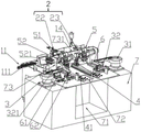
Fig. 1 is a schematic perspective view of a welding device of the present invention.
Fig. 2 is a schematic view of the front view structure of the welding device of the present invention.
Fig. 3 is a rear view structure diagram of the welding device of the present invention.
Fig. 4 is a schematic top view of the welding device of the present invention.
Fig. 5 is a schematic perspective view of the work platform of the welding device of the present invention.
Fig. 6 is a schematic perspective view of a feeding table of the welding device of the present invention.
Fig. 7 is a schematic perspective view of the material distributing table of the welding device of the present invention.
Reference is made to the accompanying drawings in which: 1-lead wire forming module, 11-lead wire assembly, 12-cut wire assembly, 13-tin dipping assembly, 14-support plate, 111-lead wire hole, 121-fixing mechanism, 122-cut wire mechanism, 131-tin dipping rotating mechanism, 132-tin dipping fixing clamp, 133-tin furnace, 2-lead wire feeding module, 21-feeding table, 22-first clamping assembly, 23-second clamping assembly, 221-moving cylinder, 222-first clamp, 231-second clamping moving mechanism, 232-second clamp, 211-wire clamping device, 212-rotating mechanism, 2111-positioning groove, 3-plug feeding module, 31-vibrating disc, 32-straight vibrating mechanism, 33-material distributing mechanism, 321-plug feeding chute, 331-material distributing moving mechanism, 332-material distributing table, 3321-material distributing groove, 4-operation platform, 41-operation moving mechanism, 42-plug welding station, 421-lead wire, 5-welding module, 51-welding moving mechanism, 52-welding moving mechanism, 731-welding module, 6-welding module, transport module, 62-73-welding head moving mechanism, 7-collecting window, base moving mechanism, 62-73-collecting window, and collecting window.
Detailed Description
The technical solutions of the embodiments of the present application will be described clearly and completely with reference to the accompanying drawings, and it is obvious that the described embodiments are some, but not all, of the embodiments of the present application. All other embodiments obtained by a person of ordinary skill in the art based on the embodiments in the present application without any creative effort belong to the protection scope of the embodiments in the present application.
In the description of the embodiments of the present application, it should be noted that the terms "center", "upper", "lower", "left", "right", "vertical", "horizontal", "inner", "outer", and the like indicate orientations or positional relationships based on orientations or positional relationships shown in the drawings, and are only for convenience of description of the embodiments of the present application and for simplicity of description, but do not indicate or imply that the devices or elements referred to must have specific orientations, be configured in specific orientations, and operate, and thus, should not be construed as limiting the embodiments of the present application.
In the description of the embodiments of the present application, it should be noted that unless otherwise explicitly stated or limited, the terms "mounted," "connected" and "connected" should be interpreted broadly, and may be, for example, a fixed connection, an exchangeable connection, an integrated connection, a mechanical connection, an electrical connection, a direct connection, an indirect connection through an intermediate medium, and a communication between two elements. Specific meanings of the above terms in the embodiments of the present application can be understood in specific cases by those of ordinary skill in the art.
This application is implemented to disclose a neotype welding set, indicates a full-automatic plug pin line welding set especially.
As shown in fig. 1 to 7, the full-automatic plug pin wire welding device provided in the embodiment of the present application includes a pin wire forming module 1, a pin wire feeding module 2, a plug feeding module 3, an operation platform 4, a welding module 5, a transportation module 6, and a base 7.
The lead wire forming module 1 is a lead wire generating part of the welding device and is responsible for processing a lead wire into a lead wire and providing a raw material lead wire for welding operation; the pin wire feeding module 2 is a feeding part of the welding device and is responsible for feeding pin wires, and can control the pin wires to be fed at a specified position on the operation platform 4, so that feeding guarantee is provided for welding work; the plug feeding module 3 is a feeding part of the welding device and is responsible for feeding plugs, the plugs are fed onto the material distribution table 332 and are arranged in order, subsequent transportation to the operation platform 4 is facilitated, and feeding guarantee is provided for welding work; the operation platform 4 is a part of the welding device for bearing welding operation, is responsible for fixing the plug and the pin wire, and can position the plug and the pin wire, so that the subsequent welding operation can be stably operated, and the welding stability is provided for the operation of a welding machine; the welding module 5 is a welding machine part of the welding device and is responsible for welding the plug and the pin wire; the transportation module 6 is a transportation part of the welding device and is responsible for transporting the plug to the operation platform 4 in the early stage of welding, and transporting the welded plug to the collection window 72 after welding is finished, so that transportation and collection guarantee is provided for welding work; the base 7 is the bearing part and the collecting part of the welding device and is responsible for bearing other components of the welding device, and meanwhile, a collecting groove 71 is arranged in the base 7 and can collect welded plugs.
A collecting groove 71 is formed in the base 7 and used for collecting the welded plug; a collecting window 72 communicated with the collecting tank 71 is formed in the front end of the upper surface of the base 7, and a supporting frame 73 is arranged at the rear end of the upper surface; a connecting plate 731 is arranged on the support frame 73; the support bracket 73 is a bearing part of the welding device.
The pin wire feeding module 2 comprises a feeding table 21, a first clamping assembly 22 and a second clamping assembly 23; the feeding table 21 is used for feeding equivalent lead wires and positioning the action of clamping the lead wires by the second clamping assembly 23; the first clamping assembly 22 is used for transporting and feeding the processed pin wires to the feeding table 21.
The welding modules 5 and the second clamping assemblies 23 are respectively two groups and are respectively arranged on the connecting plate 731; one side surface of the connecting plate 731 is connected with the two groups of welding modules 5, and the other side surface of the connecting plate 731 is connected with the two groups of second clamping assemblies 23; the plug feeding modules 3, the operation platform 4 and the transportation modules 6 are respectively arranged at the left end and the right end of the upper surface of the base 7; the lead wire forming module 1 is arranged above the base 7.
The lead wire forming module 1 comprises a wire inlet component 11, a wire cutting component 12, a tin wetting component 13 and a supporting plate 14; the wire inlet assembly 11 is a feeding part of a wire and is responsible for feeding a raw material wire of a pin wire; the wire cutting component 12 is a wire cutting part of the wire and is responsible for cutting the wire into lead wires with uniform specification and length; the tin dipping component 13 is a tin dipping part of the pin wire and is responsible for finishing tin dipping operation on the pin wire; the supporting plate 14 is a bearing part and is responsible for bearing and connecting other components.
The wire inlet assembly 11 is provided with a plurality of wire inlet holes 111, the plurality of wire inlet holes 111 are wire inlet openings of wires, one wire is placed into each wire inlet opening, a plurality of wires can be combed, and inconvenience in operation caused by mutual entanglement of the wires is prevented; the wire cutting assembly 12 comprises a fixing mechanism 121 and a wire cutting mechanism 122, and the conducting wires are fixed by the fixing mechanism, so that the length specification of each wire cutting is uniform; the tin dipping assembly 13 comprises a tin dipping rotating mechanism 212131, a tin dipping fixing clamp 132 and a tin furnace 133, wherein the tin dipping fixing clamp 132 is arranged on the supporting plate 14 and connected with the tin dipping rotating mechanism 212131; the tin furnace 133 is installed below the tin dipping fixing clip 132; the clipped pin wire is clamped and fixed by the tin dipping fixing clamp 132, under the operation of the tin dipping rotating mechanism 212131, the tin dipping fixing clamp 132 rotates, the pin wire moves to the tin furnace 133 below, and the tin dipping operation is carried out on the pin wire; the supporting plate 14, the tin furnace 133, the fixing mechanism 121 and the wire cutting mechanism 122 are all arranged on the upper surface of the base 7.
The lead wire feeding module 2 comprises a feeding table 21, a first clamping assembly 22 and a second clamping assembly 23; the first clamping assembly 22 is arranged above the supporting plate 14, and the first clamping assembly 22 comprises a moving cylinder 221 and a first clamp 222; the first clamping assembly 22 clamps and fixes the lead wires through the first clamp 222, and transports the lead wires to the feeding table 21 through the moving cylinder 221;
the second grasping assembly 23 includes a second grasping movement mechanism 231 and a second gripper 232; the feeding table 21 is arranged above the base 7; the feeding table 21 comprises a wire clamping device 211 and a rotating mechanism 212, the wire clamping device 211 clamps and fixes the lead wires, and the rotating mechanism 212 realizes the movement of the wire clamping device 211 to a position suitable for the positioning and wire clamping of the clamping assembly. A positioning groove 2111 is formed in the wire clamping device 211; the second clamp 232 is matched with the positioning groove 2111, the second clamp 232 moves to the positioning groove 2111 to clamp the lead wire under the operation of the second clamping moving mechanism 231, meanwhile, the lead wire is loosened by the wire clamping device 211, the lead wire is transported by the second clamping moving mechanism 231, and the lead wire is transported to the working platform.
The two groups of plug feeding modules 3 are respectively positioned at two sides of the supporting frame 73; the vibration disc 31 is connected with a direct vibration mechanism 32; the direct vibration mechanism 32 is provided with a plug feeding chute 321; the plug is transported to the direct vibration mechanism 32 through the operation of the vibration plate 31, and enters the plug feeding chute 321, so that the plug is displaced along the feeding chute.
The material distributing mechanism 33 comprises a material distributing movement mechanism 331 and a material distributing table 332; the material distributing table 332 is provided with a plurality of material distributing grooves 3321. The material distributing table 332 moves to the direct vibration mechanism 32 through the material distributing movement mechanism 331 and is in butt joint with the direct vibration mechanism 32, and the material distributing groove 3321 on the material distributing table 332 is in butt joint with the plug feeding chute 321 of the direct vibration mechanism 32; the four distribution grooves 3321 are sequentially abutted with the plug feeding chute 321 of the direct vibration mechanism 32 through the distribution movement mechanism 331, each time the abutting distribution table 332 receives one plug from the direct vibration mechanism 32 through the distribution groove 3321, and after the distribution table 332 receives the plugs, the plugs are transported to the working range of the transport module 6 through the distribution movement mechanism 331 to wait for the transport module 6 to operate and take the plugs away.
The two groups of the transportation modules 6 are respectively arranged at the two sides of the collection window 72; the transport module 6 includes a plug gripping mechanism 61 and a transport movement mechanism 62. The transportation module 6 moves above the material distributing table 332 through the transportation movement mechanism 62 to correspond to the material distributing groove 3321 on the material distributing table 332; the transport module 6 picks up the plug from the material separating table 332 by the plug pick-up mechanism 61, and then transports to the work platform 4 by the transport movement mechanism 62.
The two groups of working platforms 4 are respectively positioned at two sides of the collecting window 72; the lower end of the operation platform 4 is connected with an operation movement mechanism 41, and the upper end is provided with a plurality of plug welding stations 42; the transportation module 6 clamps the plug and moves to the upper side of the operation platform 4 through the transportation motion mechanism 62, and the plug is conveyed to the plug welding station 42 at the upper end of the operation platform 4, so that the fixed positioning of the plug is realized.
Pin wire positioning holes 421 are respectively formed in two ends of the plug welding station 42, the pin wires are conveyed to the operation platform 4 through the pin wire feeding module 2, and the pin wire positioning holes 421 are inserted, so that the pin wires are positioned. After the pin wires and the plugs are all conveyed to the operation platform 4 and the positioning is completed, the operation platform 4 moves to the working range of the welding module 5.
The welding module 5 comprises a welding motion mechanism 51 and a welding assembly 52, wherein the welding assembly 52 moves above the working platform 4 through the welding motion mechanism 51 and corresponds to the welding position of the working platform 4; two welding heads 521 are arranged on the welding assembly 52, and two plugs can be welded simultaneously by one operation of the welding module 5. Two sets of welding modules 5 are provided, so that four plugs can be welded at the same time in one welding operation.
A visual detection assembly is arranged at the upper end of the supporting frame 73; and two CCD camera mechanisms are arranged on the visual detection assembly. The welding device monitors the operation of a welding machine of the welding device through the CCD camera mechanism, and the precision and the stability of the welding operation are ensured.
After the welding operation is completed, the transport module 6 clamps and transports the welded plug to the collection window 72, so that the collection work of the plug is realized.
The working principle is as follows: a user of the welding device sends a lead to the wire cutting assembly 12 through the wire inlet assembly 11 after penetrating through the wire inlet, and the lead is fixed by the fixing assembly of the wire cutting assembly 12, so that the lead wires with uniform length and specification are automatically cut by the wire cutting mechanism 122; the clipped pin wire is clamped and fixed by the tin dipping fixing clamp 132, under the operation of the tin dipping rotating mechanism 212131, the tin dipping fixing clamp 132 rotates, the pin wire moves to the tin furnace 133 below, and the tin dipping operation is carried out on the pin wire, so that the molding operation of the pin wire is completed; the first gripper assembly 22 grips and fixes the lead wires by the first gripper 222, and transports the lead wires to the feed table 21 by the moving cylinder 221.
While the above process is running, the user puts the plug to be welded into the vibration plate 31; the plugs are transported to the direct vibration mechanism 32 under the operation of the vibration disc 31 and transported to the material distribution mechanism 33 through the plug feeding chute 321 of the direct vibration mechanism 32; the transportation module 6 clamps the plug from the material distribution mechanism 33 and transports the plug to a plug welding station 42 of the operation platform 4, so as to realize the welding, fixing and positioning of the plug.
After the plug is conveyed to the plug welding station 42, the second clamping assembly 23 is positioned through the positioning groove 2111 on the feeding table 21, clamps the lead wires, conveys the lead wires to the operation platform 4, and inserts the lead wires into the lead wire positioning holes 421 to realize the welding, fixing and positioning of the lead wires; the operation platform 4 moves to the operation range of the welding module 5 through the operation movement mechanism 41, the welding module 5 positions the welding position on the operation platform 4, and welding operation is performed after positioning is completed, two welding heads 521 are arranged on one group of welding assemblies 52, one group of welding assemblies 52 can perform welding operation on two plugs at the same time, two groups of welding assemblies 52 are arranged on the welding device, and one welding operation can perform welding operation on four plugs at the same time; after the welding is completed, the transport module 6 clamps the welded plug and transports the welded plug to the collection window 72, so that the collection work of the plug is realized. The visual detection assembly is arranged on the welding machine device, so that the welding machine operation of the welding device can be monitored, and the precision and the stability of the welding operation are ensured.
The novel welding device has the characteristics of automatic processing of raw materials, automatic welding operation, stable operation, labor cost reduction and production efficiency improvement.
The above, it is only the preferred embodiment of the present invention, not right the technical scope of the present invention makes any restriction, the technical personnel of the industry, under this technical scheme's enlightenment, can do some deformation and modification, all the basis the utility model discloses a technical essence is to any modification, the equivalent change and the modification of the above embodiment do, all still belong to the technical scheme's scope of the present invention.
Claims (10)
1. The utility model provides a full-automatic plug pin line welding set which characterized in that: the welding device comprises a pin wire forming module, a pin wire feeding module, a plug feeding module, an operation platform, a welding module, a transportation module and a base;
a collecting tank is arranged in the base;
the front end of the upper surface of the base is provided with a collecting window communicated with the collecting tank, and the rear end of the upper surface is provided with a supporting frame;
the support frame is provided with a connecting plate;
the pin wire feeding module comprises a feeding table, a first clamping assembly and a second clamping assembly;
the welding modules and the second clamping assemblies are respectively arranged on the connecting plate;
one side surface of the connecting plate is connected with the two groups of welding modules, and the other side surface of the connecting plate is connected with the two groups of second clamping assemblies;
the plug feeding modules, the operation platform and the transportation modules are respectively arranged at the left end and the right end of the upper surface of the base;
the pin wire forming module is arranged above the base.
2. The full-automatic plug pin wire welding device according to claim 1, characterized in that: the lead wire forming module comprises a wire inlet assembly, a wire cutting assembly, a tin adhering assembly and a supporting plate;
the wire inlet assembly is provided with a wire inlet hole;
the wire cutting assembly comprises a fixing mechanism and a wire cutting mechanism;
the tin dipping assembly comprises a tin dipping rotating mechanism, a tin dipping fixing clamp and a tin furnace;
the supporting plate, the tin furnace, the fixing mechanism and the wire cutting mechanism are all arranged on the upper surface of the base;
the first clamping assembly is arranged above the supporting plate.
3. The full-automatic plug pin wire welding device according to claim 2, characterized in that: the tin dipping fixing clamp is arranged on the supporting plate and is connected with the tin dipping rotating mechanism;
the tin furnace is arranged below the tin dipping fixing clamp.
4. The full-automatic plug pin wire welding device according to claim 1, characterized in that: the first clamping assembly comprises a moving cylinder and a first clamp;
the second clamping assembly comprises a second clamping moving mechanism and a second clamp;
the feeding table is arranged above the base;
the feeding table comprises a wire clamping device and a rotating mechanism.
5. The full-automatic plug pin wire welding device according to claim 4, characterized in that:
the wire clamping device is provided with a positioning groove;
the second clamp is matched with the positioning groove.
6. The full-automatic plug pin wire welding device according to claim 1, characterized in that: the welding module comprises a welding motion mechanism and a welding assembly;
two welding heads are arranged on the welding assembly.
7. The full-automatic plug pin wire welding device according to claim 1, characterized in that: the plug feeding module comprises a vibrating disc, a direct vibrating mechanism and a distributing mechanism;
the vibration disc is connected with the direct vibration mechanism;
the direct vibration mechanism is provided with a plug feeding chute;
the material distribution mechanism comprises a material distribution movement mechanism and a material distribution platform;
the material distributing table is provided with a plurality of material distributing grooves.
8. The full-automatic plug pin wire welding device according to claim 1, characterized in that: the transportation module comprises a plug clamping mechanism and a transportation movement mechanism.
9. The full-automatic plug pin wire welding device according to claim 1, characterized in that: the lower end of the operation platform is connected with an operation movement mechanism, and the upper end of the operation platform is provided with a plurality of plug welding stations;
and pin wire positioning holes are respectively formed at two ends of the plug welding station.
10. The full-automatic plug pin wire welding device according to claim 8, wherein: the plug clamping mechanism can respectively correspond to the material distribution mechanism, the operation platform and the collection window after being displaced by the transportation movement mechanism.
Priority Applications (1)
| Application Number | Priority Date | Filing Date | Title |
|---|---|---|---|
| CN202221496549.0U CN218533255U (en) | 2022-06-15 | 2022-06-15 | Full-automatic plug pin line welding set |
Applications Claiming Priority (1)
| Application Number | Priority Date | Filing Date | Title |
|---|---|---|---|
| CN202221496549.0U CN218533255U (en) | 2022-06-15 | 2022-06-15 | Full-automatic plug pin line welding set |
Publications (1)
| Publication Number | Publication Date |
|---|---|
| CN218533255U true CN218533255U (en) | 2023-02-28 |
Family
ID=85258931
Family Applications (1)
| Application Number | Title | Priority Date | Filing Date |
|---|---|---|---|
| CN202221496549.0U Active CN218533255U (en) | 2022-06-15 | 2022-06-15 | Full-automatic plug pin line welding set |
Country Status (1)
| Country | Link |
|---|---|
| CN (1) | CN218533255U (en) |
-
2022
- 2022-06-15 CN CN202221496549.0U patent/CN218533255U/en active Active
Similar Documents
| Publication | Publication Date | Title |
|---|---|---|
| CN111531238A (en) | Transformer welding and assembling integrated production line | |
| CN218533255U (en) | Full-automatic plug pin line welding set | |
| CN109648276B (en) | Chain and processing method and system thereof | |
| CN111673317B (en) | Full-automatic negative electrode welding machine and battery | |
| CN109625897B (en) | Chain feeding and conveying device | |
| CN218555994U (en) | Plug pin line welding device | |
| CN218225523U (en) | Clamping device and processing equipment | |
| CN216966963U (en) | Automatic brush cutting machine for storage battery tabs | |
| CN215188142U (en) | Automatic welding point glue machine | |
| CN112886355B (en) | Full-automatic soldering tin assembly production line | |
| CN115351425A (en) | Automatic welding production line | |
| CN213080611U (en) | Automatic assembling device for LED lamp tube | |
| CN111618603B (en) | Assembling and welding production line of nickel-cadmium battery | |
| CN109604515B (en) | Chain assembling equipment and pin shaft assembling device and method | |
| CN109807282B (en) | Chain cutting device and method thereof | |
| CN114178866A (en) | Automatic wire rod aftertreatment production facility | |
| CN217254349U (en) | Soldering tin structure of motor assembling equipment | |
| CN114769977B (en) | Full-automatic turnover mechanism of graphite disc for welding photovoltaic R6 diode | |
| CN216531036U (en) | Motor end cover threading and spot welding automaton | |
| CN217316751U (en) | Electrical detection assembling machine for connector | |
| CN217253490U (en) | Feeding structure of motor assembling equipment | |
| CN219321793U (en) | Automatic peeling and wire bending machine for single-core wire | |
| CN214602536U (en) | Automatic laser welding machine for temple wire and hinge | |
| CN109625898B (en) | Chain pin shaft conveying device | |
| CN212350776U (en) | Full-automatic inner octagonal nut welding machine |
Legal Events
| Date | Code | Title | Description |
|---|---|---|---|
| GR01 | Patent grant | ||
| GR01 | Patent grant |