CN218425510U - Forming die for processing T iron blank - Google Patents
Forming die for processing T iron blank Download PDFInfo
- Publication number
- CN218425510U CN218425510U CN202221915519.9U CN202221915519U CN218425510U CN 218425510 U CN218425510 U CN 218425510U CN 202221915519 U CN202221915519 U CN 202221915519U CN 218425510 U CN218425510 U CN 218425510U
- Authority
- CN
- China
- Prior art keywords
- base
- rod
- forming die
- processing
- spring
- Prior art date
- Legal status (The legal status is an assumption and is not a legal conclusion. Google has not performed a legal analysis and makes no representation as to the accuracy of the status listed.)
- Active
Links
Images

Landscapes
- Forging (AREA)
Abstract
The utility model discloses a forming die for processing T iron blank piece, including base, discharge apparatus, bed frame, guide arm, connecting plate, mould, pusher and power drive, be equipped with the dead slot in the base, discharge apparatus locates in the base and is located the dead slot, the bed frame is located on the base, the guide arm is located on the bed frame, the connecting plate cup joints to slide and locates on the guide arm, the top that the base was located to the mould just is connected with the connecting plate, the upper end of mould is equipped with the sprue gate, pusher locates on the bed frame and is connected with the mould, power drive locates on the bed frame and is connected with pusher. The utility model belongs to the technical field of the mould shaping, specifically indicate one kind can assist the fashioned blank to unload, improve production work efficiency's a forming die who is used for processing T iron blank.
Description
Technical Field
The utility model belongs to the technical field of the mould shaping, specifically indicate a forming die for processing T iron blank spare.
Background
T iron, also called electrician iron, its texture is pure iron, it is a component part that the sound unit forms, in the sound unit, T iron's main effect is to lead magnetic under the circumstances that the circular telegram, but it does not have remanence, T iron's blank is mainly processed through the mould and become, the existing mould is very inconvenient to take out after shaping the blank, because the blank has certain adhesion after cooling, the mould has certain adhesion, take out very hard manually, has undoubtedly reduced the work efficiency, because of this, need to improve.
SUMMERY OF THE UTILITY MODEL
In order to solve the problem, the utility model provides a can assist the fashioned blank and unload, improve production work efficiency's a forming die who is used for processing T iron blank.
In order to realize the above functions, the utility model discloses the technical scheme who takes as follows: a forming die for machining T-shaped iron blanks comprises a base, a discharging device, a base frame, a guide rod, a connecting plate, a die, a pushing device and a power driving device, wherein a hollow groove is formed in the base, the discharging device is arranged in the base and located in the hollow groove, the base frame is arranged on the base, the guide rod is arranged on the base frame, the connecting plate is sleeved and slidably arranged on the guide rod, the die is arranged above the base and connected with the connecting plate, a pouring gate is arranged at the upper end of the die, the pushing device is arranged on the base frame and connected with the die, and the power driving device is arranged on the base frame and connected with the pushing device; the discharging device comprises a cross rod, a first motor, a cam, a push rod, a limiting plate and a first spring, the cross rod is arranged on the base, the first motor is arranged on the cross rod, the first motor is arranged on the cam, the push rod penetrates through the base and is arranged on the base in a sliding mode, the limiting plate is arranged at one end of the push rod, the spring is sleeved and connected on the push rod, one end of the first spring is arranged on the limiting plate, the other end of the first spring is arranged on the base, the limiting plate can be knocked through rotation of the cam, the limiting plate pushes the push rod to stretch out and draw back quickly in the base, the formed blank can be pushed away from the base, and discharging is completed.
Further, pusher includes pendulum rod, sliding sleeve, telescopic link, link and spring two, the articulated rotation of pendulum rod is located on the bed frame, the sliding sleeve cup joints to slide and locates on the pendulum rod, the telescopic link runs through flexible slip in the bed frame and is connected with the sliding sleeve is articulated, the link is located on the mould and is connected with the telescopic link, the spring cup joints and locates on the telescopic link, the one end of spring two is located on the link and the other end is located on the bed frame, can accomplish the installation and the separation to the mould through pusher.
Furthermore, the power driving device comprises a groove plate, a gear row, a gear and a second motor, the groove plate is arranged on the base frame, the gear row is arranged in the groove plate, the gear is meshed with the gear row and rolls on the gear row and is connected with the swing rod, and the second motor is in power connection with the second gear and slides on the groove plate.
Preferably, the slotted plate is arc-shaped and the circle center is the same as the hinge point of the swing rod.
Preferably, the guide rod symmetrical die is provided with two groups.
Preferably, the push rods are provided in two groups.
Preferably, the empty groove can limit and block the limiting plate.
Preferably, the second motor is a forward and reverse rotating motor.
The utility model adopts the above structure to obtain the beneficial effects as follows: the utility model provides a pair of a forming die for processing T iron blank piece can drive pusher work through setting up power drive device, can accomplish the accurate installation of mould through pusher on the mould propelling movement arrives the base, pours through the sprue gate, can push away the blank after the shaping from the base through discharge apparatus, has saved the time of artifical unloading greatly.
Drawings
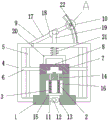
Fig. 1 is a schematic view of the overall structure of a forming die for processing a T-shaped iron blank according to the present invention;
fig. 2 is a partially enlarged view of a portion a in fig. 1.
The automatic casting machine comprises a base 1, a base 2, an empty groove 3, a discharging device 4, a base frame 5, a guide rod 6, a connecting plate 7, a mold 8, a pouring port 9, a pushing device 10, a power driving device 11, a cross rod 12, a motor I, a motor 13, a cam 14, a push rod 15, a limiting plate 16, a spring I, a spring 17, a swing rod 18, a sliding sleeve 19, a telescopic rod 20, a connecting frame 21, a spring II, a spring 22, a trough plate 23, a tooth row 24, a gear 25 and a motor II.
Detailed Description
The technical solution of the present invention will be described clearly and completely with reference to the accompanying drawings, and obviously, the described embodiments are some, but not all embodiments of the present invention. Based on the embodiments in the present invention, all other embodiments obtained by a person skilled in the art without creative work belong to the protection scope of the present invention.
In the description of the present invention, it should be noted that the terms "center", "upper", "lower", "left", "right", "vertical", "horizontal", "inner", "outer", and the like indicate orientations or positional relationships based on the orientations or positional relationships shown in the drawings, and are only for convenience of description and simplification of description, but do not indicate or imply that the device or element referred to must have a specific orientation, be constructed and operated in a specific orientation, and thus, should not be construed as limiting the present invention. Furthermore, the terms "first," "second," and "third" are used for descriptive purposes only and are not to be construed as indicating or implying relative importance. The present invention will be described in further detail with reference to the accompanying drawings.
As shown in fig. 1-2, the utility model relates to a forming die for processing T iron blank, including base 1, discharge apparatus 3, bed frame 4, guide arm 5, connecting plate 6, mould 7, pusher 9 and power drive device 10, be equipped with dead slot 2 in the base 1, discharge apparatus 3 locates in base 1 and is located dead slot 2, bed frame 4 is located on base 1, guide arm 5 is located on bed frame 4, connecting plate 6 cup joints and slides on guide arm 5, mould 7 locates above base 1 and is connected with connecting plate 6, the upper end of mould 7 is equipped with sprue gate 8, pusher 9 locates on bed frame 4 and is connected with mould 7, power drive device 10 locates on bed frame 4 and is connected with pusher 9; discharge apparatus 3 includes horizontal pole 11, motor 12, cam 13, push rod 14, limiting plate 15 and spring 16, horizontal pole 11 is located on base 1, motor 12 is located on horizontal pole 11, motor 12's power take off end is located to cam 13, push rod 14 runs through to slide and locates on base 1, limiting plate 15 locates the one end of push rod 14, spring 16 cup joints and locates on push rod 14, spring 16's one end is located on limiting plate 15 and the other end is located on base 1, can accomplish the striking to limiting plate 15 through cam 13's rotation, limiting plate 15 promotes push rod 14 and stretches out and draws back fast in base 1, can push away from base 1 to fashioned blank, accomplish and unload.
Pusher 9 includes pendulum rod 17, sliding sleeve 18, telescopic link 19, link 20 and two 21 springs, the articulated rotation of pendulum rod 17 is located on bed frame 4, sliding sleeve 18 cup joints and slides and locates on pendulum rod 17, telescopic link 19 runs through flexible slip in bed frame 4 and is connected with sliding sleeve 18 is articulated, link 20 is located on mould 7 and is connected with telescopic link 19, two 21 springs cup joint and locate on telescopic link 19, the one end of two 21 springs is located on connecting plate 206 and the other end is located on bed frame 4, can accomplish the installation of mould 7 and tear open from through pusher 9.
The power driving device 10 comprises a groove plate 22, a gear row 23, a gear 24 and a second motor 25, wherein the groove plate 22 is arranged on the base frame 4, the gear row 23 is arranged in the groove plate 22, the gear 24 is meshed with and rolls on the gear row 23 and is connected with the swing rod 17, and the second motor 25 is in power connection with the gear 24 and slides on the groove plate 22.
The slot plate 22 is arranged in an arc shape, and the circle center of the slot plate is the same as the hinge point of the swing rod 17.
Two groups of symmetrical dies 7 of the guide rod 5 are arranged.
The push rods 14 are provided in two groups.
The dead slot 2 can limit and block the limiting plate 15.
The second motor 25 is a forward and reverse rotating motor.
When the rapid unloading device is used, firstly, the second motor 25 is started, the gear 24 is driven to rotate, the gear 24 is meshed and rolls on the gear row 23, the gear 24 simultaneously drives the swing rod 17 to rotate, the swing rod 17 presses the telescopic rod 19 in the rotating process, the sliding sleeve 18 simultaneously slides on the swing rod 17, the telescopic rod 19 pushes the connecting frame 20, the connecting frame 20 pushes the mold 7 to move downwards, the connecting plate 6 slides on the guide rod 5, the downward moving position of the mold 7 is positioned, the mold 7 accurately slides on the base 1, pouring molding can be conducted through the pouring gate 8, after molding, the mold 7 is pulled away from the base 1 through the pushing device 9, then the first motor 12 is started, the cam 13 rotates, the limiting plate 15 is knocked, the limiting plate 15 pushes the push rod 14 to slide in the base 1, the push rod 14 can push the molded blank away from the base 1, and then the push rod 14 rapidly resets under the action of the first spring 16, so that the rapid unloading purpose is achieved, the manual unloading time is saved, and the production efficiency is improved.
The present invention and the embodiments thereof have been described above, but the description is not limited thereto, and the embodiment shown in the drawings is only one of the embodiments of the present invention, and the actual structure is not limited thereto. In summary, those skilled in the art should understand that they should not be limited to the embodiments described above, and that they can design the similar structure and embodiments without departing from the spirit of the invention.
Claims (8)
1. The utility model provides a forming die for processing T iron blank spare which characterized in that: the automatic material-discharging device comprises a base, a discharging device, a base frame, a guide rod, a connecting plate, a mold, a pushing device and a power driving device, wherein a hollow groove is formed in the base, the discharging device is arranged in the base and positioned in the hollow groove, the base frame is arranged on the base, the guide rod is arranged on the base frame, the connecting plate is sleeved and slidably arranged on the guide rod, the mold is arranged above the base and connected with the connecting plate, a pouring gate is arranged at the upper end of the mold, the pushing device is arranged on the base frame and connected with the mold, and the power driving device is arranged on the base frame and connected with the pushing device; the discharging device comprises a cross rod, a first motor, a cam, a push rod, a limiting plate and a first spring, wherein the cross rod is arranged on the base, the first motor is arranged on the cross rod, the cam is arranged at the power output end of the first motor, the push rod is arranged on the base in a penetrating and sliding mode, the limiting plate is arranged at one end of the push rod, the spring is sleeved and connected on the push rod, one end of the first spring is arranged on the limiting plate, and the other end of the first spring is arranged on the base.
2. The forming die for processing the T iron rough part according to the claim 1, characterized in that: the pushing device comprises a swing rod, a sliding sleeve, a telescopic rod, a connecting frame and a second spring, the swing rod is hinged to rotate and arranged on the base frame, the sliding sleeve is sleeved and arranged on the swing rod in a sliding mode, the telescopic rod penetrates through the sliding sleeve to slide in the base frame and is hinged to the sliding sleeve, the connecting frame is arranged on the die and is connected with the telescopic rod, the spring is sleeved and arranged on the telescopic rod, one end of the second spring is arranged on the connecting frame, and the other end of the second spring is arranged on the base frame.
3. The forming die for processing the T iron blank piece as claimed in claim 2, wherein: the power driving device comprises a slotted plate, a gear row, a gear and a second motor, wherein the slotted plate is arranged on the base frame, the gear row is arranged in the slotted plate, the gear rolls on the gear row in a meshing manner and is connected with the swing rod, and the second motor is in power connection with the second gear and slides on the slotted plate.
4. The forming die for processing the T iron blank piece as claimed in claim 3, wherein: the frid is the arc setting and the centre of a circle is the same with the pin joint of pendulum rod.
5. The forming die for processing the T iron blank piece as claimed in claim 4, wherein: the guide rod symmetrical dies are provided with two groups.
6. The forming die for processing the T iron blank piece as claimed in claim 5, wherein: the push rods are provided with two groups.
7. The forming die for processing the T-shaped iron blank according to claim 6, wherein the empty groove can limit and block the limiting plate.
8. The forming die for processing the T iron blank piece as claimed in claim 7, wherein: and the second motor is a forward and reverse rotating motor.
Priority Applications (1)
| Application Number | Priority Date | Filing Date | Title |
|---|---|---|---|
| CN202221915519.9U CN218425510U (en) | 2022-07-25 | 2022-07-25 | Forming die for processing T iron blank |
Applications Claiming Priority (1)
| Application Number | Priority Date | Filing Date | Title |
|---|---|---|---|
| CN202221915519.9U CN218425510U (en) | 2022-07-25 | 2022-07-25 | Forming die for processing T iron blank |
Publications (1)
| Publication Number | Publication Date |
|---|---|
| CN218425510U true CN218425510U (en) | 2023-02-03 |
Family
ID=85091698
Family Applications (1)
| Application Number | Title | Priority Date | Filing Date |
|---|---|---|---|
| CN202221915519.9U Active CN218425510U (en) | 2022-07-25 | 2022-07-25 | Forming die for processing T iron blank |
Country Status (1)
| Country | Link |
|---|---|
| CN (1) | CN218425510U (en) |
-
2022
- 2022-07-25 CN CN202221915519.9U patent/CN218425510U/en active Active
Similar Documents
| Publication | Publication Date | Title |
|---|---|---|
| CN205519558U (en) | A machine is got to steel aluminium die -casting fin material loading | |
| CN218425510U (en) | Forming die for processing T iron blank | |
| CN211101542U (en) | Metal casting mold with melting box | |
| CN211334304U (en) | Lid injection mold positioner | |
| CN214236250U (en) | Demoulding auxiliary device for mould | |
| CN213728898U (en) | Light alloy stamping die convenient to ejection of compact | |
| CN109049574A (en) | A kind of mold of the upper die and lower die with locking linkage function | |
| CN213410000U (en) | Cut-out press turning device | |
| CN213533758U (en) | Mould is used in processing of cosmetics packaging bottle | |
| CN211588143U (en) | Material frame mold structure | |
| CN208438531U (en) | A kind of sawdust pallet processing mold | |
| CN212826487U (en) | Mould for toy shell | |
| CN219820530U (en) | Injection molding die of compound knob | |
| CN220784737U (en) | Earphone production injection molding shearing mechanism | |
| CN214977141U (en) | Shaping die of engine tail gas filtering device | |
| CN211517652U (en) | Punching device for die production | |
| CN219667312U (en) | Quick replacement device for die ejector blocks | |
| CN215090620U (en) | Robot base mould | |
| CN210525748U (en) | Take sash bar of manipulator to get a tool | |
| CN219807428U (en) | Fixed transfer device of plastic bottle production | |
| CN219522793U (en) | Mould convenient for quick material taking for elbow production | |
| CN210061885U (en) | Tool for demolding wax statues | |
| CN213291070U (en) | Protection switch plastic mold | |
| CN219171521U (en) | Gear production mould convenient to drawing of patterns | |
| CN221089707U (en) | Plastic cup hot-pressing die |
Legal Events
| Date | Code | Title | Description |
|---|---|---|---|
| GR01 | Patent grant | ||
| GR01 | Patent grant |