CN218388940U - Environment-friendly greenhouse capable of controlling carbon dioxide - Google Patents
Environment-friendly greenhouse capable of controlling carbon dioxide Download PDFInfo
- Publication number
- CN218388940U CN218388940U CN202221059188.3U CN202221059188U CN218388940U CN 218388940 U CN218388940 U CN 218388940U CN 202221059188 U CN202221059188 U CN 202221059188U CN 218388940 U CN218388940 U CN 218388940U
- Authority
- CN
- China
- Prior art keywords
- carbon dioxide
- greenhouse
- main body
- greenhouse main
- planting
- Prior art date
- Legal status (The legal status is an assumption and is not a legal conclusion. Google has not performed a legal analysis and makes no representation as to the accuracy of the status listed.)
- Active
Links
Images


Classifications
-
- Y—GENERAL TAGGING OF NEW TECHNOLOGICAL DEVELOPMENTS; GENERAL TAGGING OF CROSS-SECTIONAL TECHNOLOGIES SPANNING OVER SEVERAL SECTIONS OF THE IPC; TECHNICAL SUBJECTS COVERED BY FORMER USPC CROSS-REFERENCE ART COLLECTIONS [XRACs] AND DIGESTS
- Y02—TECHNOLOGIES OR APPLICATIONS FOR MITIGATION OR ADAPTATION AGAINST CLIMATE CHANGE
- Y02A—TECHNOLOGIES FOR ADAPTATION TO CLIMATE CHANGE
- Y02A40/00—Adaptation technologies in agriculture, forestry, livestock or agroalimentary production
- Y02A40/10—Adaptation technologies in agriculture, forestry, livestock or agroalimentary production in agriculture
- Y02A40/25—Greenhouse technology, e.g. cooling systems therefor
Abstract
The application provides an environmental protection greenhouse of steerable carbon dioxide, includes: the greenhouse comprises a greenhouse main body, a planting area and a water treatment area, wherein the planting area and the water treatment area are arranged in the greenhouse main body; a door is arranged on one side surface of the greenhouse main body, and a first ventilation window is arranged on the opposite side surface of the greenhouse main body and the door; the planting area is provided with a carbon dioxide input pipe which penetrates through the greenhouse main body. The application provides a steerable carbon dioxide's environmental protection greenhouse collects carbon dioxide absorption and handles, sewage treatment and greenhouse plant as an organic whole, not only can absorb carbon dioxide, can also purify sewage, make the sewage after the purification reach recycle's standard once more, have energy saving and emission reduction, reduce carbon emission, environmental protection and water resource reuse's characteristics to can also adjust the concentration of the indoor carbon dioxide of temperature in real time, have in time, need not manual operation's characteristics.
Description
Technical Field
The application relates to the technical field of greenhouses, in particular to an environment-friendly greenhouse capable of controlling carbon dioxide.
Background
The society is continuously advanced, the traditional agricultural production mode cannot meet the requirement of modern civilization development, and novel agricultural facilities are pursued by people in the industry. The novel agricultural facility is a greenhouse facility, is not limited by time and space, and can be used for agricultural production in special environments such as plateaus, mountains, deserts and the like. A greenhouse, also called a greenhouse, can transmit light and keep warm (or raise temperature), and is a facility for cultivating plants. In seasons unsuitable for plant growth, the method can provide the growth period of a greenhouse and increase the yield, and is mainly used for cultivating or raising seedlings of plants such as warm vegetables, flowers and trees in low-temperature seasons. The greenhouse is of various types, such as an environmental greenhouse, a film greenhouse and a plastic board greenhouse which can control carbon dioxide. However, the existing environment-friendly greenhouse capable of controlling carbon dioxide has single function, can only be used for planting crops basically, and is difficult to realize multifunctional application.
SUMMERY OF THE UTILITY MODEL
The application provides an environment-friendly greenhouse capable of controlling carbon dioxide, the problem that the existing environment-friendly greenhouse capable of controlling carbon dioxide is single in function is solved.
The application provides an environmental protection greenhouse of steerable carbon dioxide, includes: the greenhouse comprises a greenhouse main body, a planting area and a water treatment area, wherein the planting area and the water treatment area are arranged in the greenhouse main body;
the water treatment area is sequentially provided with an ultraviolet light disinfection tank, an aeration tank, a first ecological tank, a second ecological tank and a sand filter tank along the flowing direction of sewage;
a sewage inlet is formed in one side surface of the ultraviolet disinfection tank close to the greenhouse main body; the bottom of one side surface of the sand filter chamber, which is close to the greenhouse main body, is provided with a first purified water outlet; a second purified water outlet is formed at the bottom of one side surface of the sand filter chamber close to the planting area;
the planting area comprises a planting row and a planting line, the planting row comprises a drip irrigation pipe and a planting platform; the drip irrigation pipe is arranged above the planting platform and used for irrigating plants on the planting platform, and the drip irrigation pipe is connected with the second purified water outlet;
a door is arranged on one side surface of the greenhouse main body, and a first ventilation window is arranged on one side surface of the greenhouse main body opposite to the door;
the planting area is provided with a through greenhouse a carbon dioxide input tube of the main body;
an automatic regulating valve is arranged on the carbon dioxide input pipe, a carbon dioxide concentration detector is arranged in the planting area, the carbon dioxide concentration detector is interlocked with the automatic regulating valve.
Optionally, a shading grating plate is arranged at the top of the greenhouse main body; a suspension bracket is arranged at the upper part in the greenhouse main body; the suspension bracket is provided with a lamp and a fan; the hanger is positioned higher than the first louver.
Optionally, an ultraviolet lamp is arranged in the ultraviolet disinfection tank; the aeration tank is connected with an air pump which is used for conveying air to the aeration tank; the first ecological pool is connected with a liquid level pump.
Optionally, a microclimate chamber is arranged on the greenhouse main body and extends to the outer side close to the first ventilation window.
Optionally, a second ventilation window is arranged on one side surface of the microclimate conditioning room, which is far away from the first ventilation window, and the top of the second ventilation window is flush with the bottom of the first ventilation window;
a transmission pipe is arranged below the planting platform, one end of the transmission pipe, which is positioned in the planting area, is closed, and the other end of the transmission pipe is communicated with the greenhouse main body and the microclimate adjusting chamber through an opening; two sides of the transmission pipe are respectively provided with a small hole.
Optionally, an atomizer is arranged at the bottom of the microclimate chamber, an outlet of the atomizer is aligned with the transmission pipe, and the atomizer is connected with the first purified water outlet;
the interior of one end of the transmission pipe close to the microclimate adjusting chamber is provided with a negative pressure fan, and one side of the negative pressure fan close to the microclimate adjusting chamber is provided with a protective cover.
Optionally, a control panel is arranged in the microclimate conditioning room, a grid plate is arranged on the top of the control panel, and the control panel is arranged between the transmission pipe and the second ventilation window.
Optionally, the control panel comprises a heating plate, a refrigerating plate and a dehumidifier which are stacked;
the heating plate comprises a conduit and a fin; the fins are fixedly arranged on the outer surface of the conduit;
the refrigerating plate and the heating plate have the same structure.
Optionally, a precision filter is further arranged between the atomizer and the first purified water outlet.
Optionally, an environmental monitor is disposed on the planting platform.
The application provides a steerable carbon dioxide's environmental protection greenhouse collects carbon dioxide absorption treatment, sewage treatment and greenhouse and plants as an organic whole, not only can absorb the processing carbon dioxide, can also with sewage purification such as domestic sewage, commercial sewage, surface runoff, make it reach the standard of recycle once more (for example irrigate), have energy saving and emission reduction, reduce carbon emission, environmental protection and water resource characteristics of recycling.
Drawings
In order to more clearly illustrate the embodiments of the present application or the technical solutions in the prior art, the drawings used in the embodiments or the prior art descriptions will be briefly described below, and it is obvious that the drawings in the following descriptions are some embodiments of the present application, and other drawings can be obtained by those skilled in the art without creative efforts.
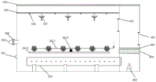
Fig. 1 is a schematic plan view of an interior of a greenhouse provided in an embodiment of the present application;
fig. 2 is a schematic view of a front view structure of a greenhouse provided in an embodiment of the present application;
fig. 3 is a schematic plan view of the inside of a greenhouse provided in another embodiment of the present application;
fig. 4 is a schematic front view of a greenhouse provided in another embodiment of the present application;
FIG. 5 is a block diagram of an embodiment of the present application the structure schematic diagram of the negative pressure fan and the protective cover;
fig. 6 is a schematic structural diagram of a control board according to an embodiment of the present application;
fig. 7 is a schematic structural diagram of a heating plate according to an embodiment of the present application.
Description of reference numerals:
1. greenhouse a main body;
101. a door;
102. a carbon dioxide input pipe;
103. a first louver;
104. a shading grating plate;
105. a suspension bracket;
106. a lamp;
107. a fan;
108. automatically adjusting the valve;
109. a carbon dioxide concentration detector;
2. a planting area;
201. planting rows;
2011. a drip irrigation pipe;
2012. a planting platform;
2013. an environment detector;
202. a conveying pipe;
2021. a negative pressure fan;
2022. a protective cover;
3. a water treatment zone;
301. a sewage inlet;
302. a first purified water outlet;
303. an ultraviolet light disinfection tank;
304. an aeration tank;
305. a first ecological pool;
306. a second ecological pool;
307. a sand filter;
308. an air pump;
309. a liquid level pump;
310. a second purified water outlet;
4. a microclimate conditioning chamber;
401. a second louver;
402. an atomizer;
403. a grid plate;
404. a control panel;
4041. heating the plate;
40411. a conduit;
40412. a fin;
4042. a refrigeration plate;
4043. a dehumidifier;
405. a precision filter.
Detailed Description
In order to make the objects, technical solutions and advantages of the embodiments of the present application clearer, the technical solutions in the embodiments of the present application are clearly and completely described below, and it is obvious that the described embodiments are a part of the embodiments of the present application, but not all of the embodiments. All other embodiments, which can be derived by a person skilled in the art from the embodiments given herein without making any creative effort, shall fall within the protection scope of the present application.
As shown in fig. 1 and 2, the present application provides an eco-greenhouse capable of controlling carbon dioxide, comprising: the greenhouse comprises a greenhouse main body 1, a planting area 2 and a water treatment area 3, wherein the planting area 2 and the water treatment area 3 are arranged inside the greenhouse main body 1;
the water treatment area 3 is provided with an ultraviolet disinfection tank 303, an aeration tank 304, a first ecological tank 305, a second ecological tank 306 and a sand filter tank 307 in sequence along the flowing direction of sewage;
a sewage inlet 301 is formed in one side surface of the ultraviolet disinfection tank 303 close to the greenhouse main body 1; the sand filter 307 is provided with a first purified water outlet 302 close to the bottom of one side surface of the greenhouse main body 1; the bottom of one side surface of the sand filter 307 close to the planting area 2 is provided with a second purified water outlet 310;
the planting area 2 comprises planting rows 201, which comprise drip irrigation pipes 2011 and planting platforms 2012; the drip irrigation pipe 2011 is arranged above the planting platform 2012 and used for irrigating plants on the planting platform 2012, and the drip irrigation pipe 2011 is connected with the second purified water outlet 310;
a door 101 is arranged on one side surface of the greenhouse main body 1, and a first ventilation window 103 is arranged on one side surface of the greenhouse main body 1 opposite to the door 101;
the planting area 2 is provided with a carbon dioxide input pipe 102 which penetrates through the greenhouse main body 1;
an automatic regulating valve 108 is arranged on the carbon dioxide input pipe 102, a carbon dioxide concentration detector 109 is arranged in the planting area 2, and the carbon dioxide concentration detector 109 is interlocked with the automatic regulating valve 108.
In the application, the inside of a greenhouse main body 1 is divided into a planting area 2 and a water treatment area 3, wherein plants, such as crops like vegetables and fruits, or other plants with economic value, such as flowers and the like, are planted in the planting area 2; the water treatment area 3 is used for treating sewage, such as domestic sewage, commercial sewage, surface runoff and the like with high nitrogen and phosphorus content. The carbon dioxide input pipe 102 arranged on the greenhouse main body 1 is used for supplying carbon dioxide into the greenhouse main body 1, the carbon dioxide is carbon dioxide gas generated in the production process of aerated bricks, and the supplied carbon dioxide can be absorbed and utilized by plants planted in the planting area 2, so that the emission of the carbon dioxide is reduced, and the greenhouse main body 1 has positive significance for realizing a low-carbon target.
An automatic adjusting valve 108 is arranged on the carbon dioxide input pipe 102, the automatic adjusting valve 108 is interlocked with a carbon dioxide concentration detector 109 in the planting area 2 in the greenhouse main body 1, and the carbon dioxide concentration detector 109 is arranged in the middle position of the planting area 2 so as to ensure the accuracy of the measured carbon dioxide concentration.
In use, the carbon dioxide concentration detector 109 is used for monitoring the concentration of carbon dioxide in the greenhouse main body 1 and feeding data back to the automatic regulating valve 108, and if the concentration of carbon dioxide in the greenhouse main body 1 is lower than a preset value, the automatic regulating valve 108 is opened to supply carbon dioxide into the greenhouse main body 1; if the concentration of the carbon dioxide in the greenhouse main body 1 is higher than the preset value, the automatic regulating valve 108 is closed, and the supply of the carbon dioxide to the greenhouse main body 1 is stopped; the carbon dioxide concentration detector 109 is interlocked with the automatic regulating valve 108, so that the content of the carbon dioxide in the greenhouse main body 1 can be dynamically regulated in real time, and the greenhouse has the characteristics of timeliness and no need of manual operation.
The water treatment area 3 comprises an ultraviolet disinfection tank 303, an aeration tank 304, a first ecological tank 305, a second ecological tank 306 and a sand filter tank 307.
The sewage is firstly input into the ultraviolet disinfection tank 303 through the sewage inlet 301, the ultraviolet disinfection is carried out under the stirring condition to kill microorganisms in the sewage, the killed microorganisms can be used as nutrients of flora inoculated by the aeration tank 304, and the pressure of the subsequent water tank for sewage treatment can be reduced by arranging the ultraviolet disinfection tank 303. The wastewater disinfected by ultraviolet light overflows into the aeration tank 304, the aeration tank 304 is filled with acclimated activated sludge, and the corresponding acclimated activated sludge can be selected according to different types of wastewater to be treated, for example, for wastewater with high nitrogen content, activated sludge containing a large amount of nitrifying bacteria can be acclimated for use. The sewage in the aeration tank 304 is treated and overflows into the first ecological tank 305, the bottom layer of the first ecological tank 305 is domesticated activated sludge, algae such as chlorella, goldfish algae, synechococcus, stigmata and the like are cultured in the water, aquatic plants such as cattail, reed, canna, water spinach, swamp cabbage, drotocrella japonica and the like are cultured on the sewage liquid surface in the form of a floating bed, and a micro-ecological system for purifying the sewage of a bacterium-algae-floating bed is formed in the first ecological tank 305 and is used for further purifying the sewage.
In the second ecological pool 306, aquatic weeds, algae, shells, shrimps, crabs and the like for purifying water quality are cultivated, and the aquatic weeds such as water pine grass, water bamboo leaves, duckweed and the like; algae such as Goldfish algae, anabaena, chlorella, etc. In the second ecological pool, another micro-ecological system formed by waterweeds, algae and aquatic animals can further purify the quality of the sewage, so that the quality of the sewage can be reused.
The sand filter 307 is filled with quartz sand, particles of the quartz sand are filled according to the upper sparse and lower dense modes, particles in water can be filtered in a grading mode, blockage caused by long-term use is avoided, and the sand filter 307 is convenient to back flush through the upper sparse and lower dense filling modes. The water after the ecological treatment in the second ecological tank 306 overflows into the sand filter 307, and suspended particulate matters in the water can be removed through the filtration of the sand filter 307, so that the turbidity of the discharged water is reduced. In addition, the water backflushed in the sand filter 307 can be overflowed to the second ecological tank 306 in a counter-current manner for further treatment, which can reduce the discharge of sewage for maintenance of the sand filter 307. The purified water obtained after being treated by the sand filter 307 can be discharged from the first purified water outlet 302 and collected for reuse; and can also be discharged via a second purified water outlet 310, which can be used for watering the plants in the growing area 2.
In addition, because the water treatment area 3 treats the sewage by using a biochemical technology, gases such as carbon dioxide are often generated in the treatment process, and the gases can pollute the environment if the gases are directly discharged, in the environment-friendly greenhouse capable of controlling the carbon dioxide, the water treatment area 3 and the planting area are both arranged in the greenhouse main body 1, the gases generated in the water treatment process can be absorbed and removed by plants in the planting area 2, wherein the planting area 2 can be planted in a targeted manner according to the type of the sewage to be treated. The process does not need additional cleaning means, thereby having the advantages of reducing the treatment cost and protecting the environment.
In the present application, the planting platform 2012 is used to plant plants. Drip irrigation lines 2011 are provided within the rows 201. The plant is irrigated by adopting a drip irrigation mode, wherein the drip irrigation mode is that water is sent to the roots of the plants for local irrigation by utilizing a plastic pipeline through an orifice or a water dropper on a capillary tube with the diameter of about 10mm, the drip irrigation mode does not damage the soil structure, the water, fertilizer, gas and heat in the soil keep a good condition suitable for the growth of the plants, the evaporation loss is small, the ground runoff is not generated, the deep seepage is hardly caused, and the drip irrigation mode is a water-saving irrigation mode. The irrigation period of the drip irrigation is short, and the drip irrigation can be performed frequently; the required working pressure is low, the irrigation quantity can be accurately controlled, the ineffective evaporation between plants can be reduced, and the waste of water can not be caused; drip irrigation also has the advantage of automated management. Planting row 201 is provided with a plurality ofly in this application, correspondingly, plant platform 2012 and drip irrigation pipe 2011 and plant row 201 one-to-one and set up a plurality ofly.
In this application, the door 101 and the first ventilation window 103 that set up on the greenhouse main part 1 set up relatively, the inside and outside air cycle convection current of greenhouse of being convenient for.
In the application, the interior of a greenhouse main body 1 is divided into a planting area 2 and a water treatment area 3, wherein plants are planted in the planting area 2; the water treatment area 3 is used for treating sewage, gas generated in the sewage treatment process can be absorbed and removed by plants in the planting area 2, the emission of harmful gas can be reduced, and the plants in the greenhouse can absorb and utilize carbon dioxide input from the outside, so that the positive significance of reducing pollution and greenhouse gas emission is achieved. The application provides a steerable carbon dioxide's environmental protection greenhouse collects carbon dioxide absorption treatment, sewage treatment and greenhouse and plants as an organic wholely, not only can absorb the processing carbon dioxide, reduces the emission of carbon dioxide, can also with sewage purification such as domestic sewage, commercial sewage, surface runoff, make it reach the standard of recycle once more (for example irrigation), have energy saving and emission reduction, reduce treatment cost, reduce carbon emission, environmental protection and water resource recycle's characteristics.
Optionally, an ultraviolet lamp is arranged in the ultraviolet disinfection tank 303; the aeration tank 304 is connected with an air pump 308, and the air pump 308 is used for delivering air to the aeration tank 304; the first ecological pool 305 is connected with a liquid level pump 309.
In this application, be provided with the ultraviolet lamp in the ultraviolet ray disinfection pond 303, the irradiation intensity of ultraviolet lamp is as follows: 253.7nm of radiation at a voltage of 220V, an ambient relative humidity of 60% and a temperature of 20 DEG CThe ultraviolet intensity is 70-200 mu W/cm 2 . The high-intensity ultraviolet lamp irradiation can improve the disinfection and sterilization efficiency of the ultraviolet disinfection tank 303.
The aeration tank 304 is connected with an air pump 308, and the air pump 308 inputs air into the aeration tank 304 to play a role in increasing the oxygen content of the sewage in the aeration tank 304 and stirring.
The first ecological pool 305 is connected with a liquid level pump 309 for timely supplementing the water level of the first ecological pool 305.
As shown in fig. 2, optionally, a light shielding grating plate 104 is arranged on the top of the greenhouse body 1; the upper part in the greenhouse main body 1 is provided with a suspension bracket 105; a lamp 106 and a fan 107 are arranged on the suspension bracket 105; the hanger 105 is positioned higher than the first louver 103.
In this application, the structure of the similar shutter of light-shielding grid plate 104, thereby the angle that can adjust the grid plate changes the intensity of incident light, and every grid plate can adopt solar cell panel, not only plays the effect of shading, can also change solar energy into the electric energy to reduce manufacturing cost. The hanging frame 105 is provided with a plurality of lamps 106 for supplying light to the plants in the planting area 2 at night or in rainy days, and has a lighting function. The fan 107 is used to promote the flow of air in the greenhouse, and the number of the fans 107 may be plural.
As shown in fig. 3 and 4, a microclimate chamber 4 is optionally provided to extend from the greenhouse body 1 to the outside near the first ventilation window 103.
Greenhouse main part 1 extends the outside that is close to first ventilation window 103 in this application and sets up microclimate control room 4, and temperature, humidity, air current circulation etc. in the adjustable greenhouse main part 1 of microclimate control room 4.
Optionally, a second louver 401 is disposed on a side of the microclimate room 4 away from the first louver 103, and a top of the second louver 401 is flush with a bottom of the first louver 103.
A conveying pipe 202 is arranged below the planting platform 2012, one end of the conveying pipe 202 in the planting area 2 is closed, and the other end of the conveying pipe is communicated with the greenhouse main body 1 and the microclimate adjusting chamber 4 through an opening; two sides of the transmission pipe 202 are respectively provided with a small hole.
The microclimate room 4 sets up second ventilation window 401 in this application, and second ventilation window 401 and first ventilation window 103 are not on same horizontal plane, and this kind of staggered is provided with and does benefit to the reinforcing air convection.
The transmission pipe 202 is arranged below the planting platform 2012, so that atomized water can directly act on plants, and loss is reduced; the two sides of the transmission pipe 202 are respectively provided with small holes for dispersing the airflow input into the transmission pipe 202, so that the airflow input into the planting area 2 from the transmission pipe 202 is uniformly distributed, and the small holes also have the function of pressure reduction, so that the pressure of the airflow input into the transmission pipe 202 can be effectively dispersed and reduced, the output airflow is smooth and soft, the impact of the airflow on plants or other devices in the planting area 2 is reduced, and the effect of protecting the plants and the devices is also achieved; the conveying pipes 202 in the present application are provided in a plurality in one-to-one correspondence with the planting platforms 2012.
Optionally, the microclimate chamber 4 is provided at the bottom with an atomizer 402, the outlet of the atomizer 402 is aligned with the transfer pipe 202, and the atomizer 402 is connected with the first purified water outlet 302.
As shown in fig. 5, a negative pressure fan 2021 is disposed inside one end of the conveying pipe 202 close to the microclimate conditioning chamber 4, and a protective cover 2022 is disposed on one side of the negative pressure fan 2021 close to the microclimate conditioning chamber 4.
An atomizer 402 is connected to the first purified water outlet 302 for atomizing purified water, the atomizer 402 being, for example, an ultrasonic atomizer. In the application, one end of the transmission pipe 202, which is close to the atomizer 402 in the microclimate adjusting chamber 4, is provided with the negative pressure fan 2021, and in actual work, purified water atomized by the atomizer 402 is sucked into the transmission pipe 202 under the action of the negative pressure fan 2021 and then is discharged into the planting area 2 through the small holes on two sides of the transmission pipe 202 to adjust the humidity of the planting area 2.
The outlet of the atomizer 402 is aligned with the delivery tube 202, which also reduces the loss of atomized water during flow.
As shown in fig. 4, optionally, a control panel 404 is provided inside the microclimate chamber 4, a louver 403 is provided on the top of the control panel 404, and the control panel 404 is provided between the transfer pipe 202 and the second louver 401.
As shown in fig. 6 and 7, optionally, the control board 404 includes a heating plate 4041, a cooling plate 4042, and a dehumidifier 4043 arranged in a stack; the heating plate 4041 includes a conduit 40411 and fins 40412; the fins 40412 are fixedly disposed on the outer surface of the conduit 40411; the cooling plate 4042 and the heating plate 4041 are identical in construction.
In the present application, the grid plate 403 has the functions of ventilating and suspending the control plate 404, the control plate 404 includes a heating plate 4041 and a cooling plate 4042, the heating plate 4041 has the same structure as the fin-type heating tube, fins 40412 are densely distributed outside the conduit 40411, and a heating medium, such as water or heat conducting oil with a temperature of 50-60 ℃, flows in the conduit 40411; the structure of the cooling plate 4042 is the same as the structure of the heating plate 4041, except that a cooling medium such as chilled brine or circulating water flows in the conduit 40411; the dehumidifier 4043 is used to dehumidify the air, reduce the humidity of the air, and ensure the normal growth of the plants in the planting area 2. The heating plate 4041, the refrigerating plate 4042 and the dehumidifier 4043 are stacked, the stacking order is not limited, and the heating plate 4041, the refrigerating plate 4042 and the dehumidifier 4043 respectively work independently.
Optionally, a fine filter 405 is also provided between the atomizer 402 and the first purified water outlet 302.
The shell of the precision filter (also called a safety filter) is generally made of stainless steel, tubular filter elements such as PP melt-blown filter elements, wire-fired filter elements, folded filter elements, titanium filter elements, activated carbon filter elements and the like are adopted as filter elements inside the precision filter, and different filter elements are selected according to different filter media and design processes so as to meet the requirement of effluent quality. The fine filter 405 is provided to filter suspended matters in the purified water that cannot be intercepted by the intercepting sand filter 307, so as to prevent the purified water suspended matters from blocking the atomizer 402.
Optionally, an environment monitor 2013 is disposed on the planting platform 2012.
The environment monitors 2013 are used for monitoring atmospheric indexes such as temperature, humidity and oxygen value in the greenhouse main body 1 in real time, the monitored index data are sent to a data processing terminal such as a computer, and an operator regulates and controls all indexes and equipment in the greenhouse main body in real time according to the data.
According to the environment-friendly greenhouse capable of controlling carbon dioxide, the interior of a greenhouse main body 1 is divided into a planting area 2 and a water treatment area 3, in actual use, carbon dioxide gas is introduced into the greenhouse main body 1 according to environmental indexes in the greenhouse main body 1, and plants in the planting area 2 recycle the carbon dioxide gas through photosynthesis; the sewage to be treated enters the water treatment area 3, is disinfected and killed by the ultraviolet disinfection tank 303, overflows into the aeration tank 304, organic matters and soluble inorganic salts in the sewage are decomposed and removed by activated sludge in the aeration tank 304, the COD value of the sewage is reduced, organic matters capable of being utilized by plants are generated, the sewage treated in the aeration tank 304 overflows into the first ecological tank 305 again, and is further decomposed and utilized by algae and aquatic plants in the first ecological tank 305, namely, the sewage is further purified; the sewage entering the second ecological pool 306 is purified again by water plants, algae, shells, shrimps, crabs and the like with purified water quality to reach the irrigation standard, finally the purified sewage is filtered and output by the sand filter 307, one part of the purified sewage is output to other scenes needing water, the other part of the purified sewage is used for irrigating plants in the planting area 2, and gas such as carbon dioxide generated in the sewage treatment process of the water treatment area 3 can also be absorbed by the plants in the planting area 2.
In another possible implementation, the greenhouse main body 1 is provided with a microclimate chamber 4 extending near the outer side of the first ventilation window 103; a second ventilation window 401 is arranged on one side surface of the microclimate adjusting chamber 4 far away from the first ventilation window 103, an atomizer 402 and a control panel 404 are arranged in the microclimate adjusting chamber 4, wherein the control panel 404 comprises a heating plate 4041, a refrigerating plate 4042 and a dehumidifier 4043, and the heating, refrigerating and dehumidifying functions can be realized. The micro-climate chamber 4 is communicated with the planting area 2 through a transmission pipe 202.
In actual use, if the temperature of the environment in the greenhouse main body 1 needs to be raised (or lowered), the second ventilation window 401 is closed, the first ventilation window 103, the heating plate 4041 (or the cooling plate 4042) on the control panel 404 and the negative pressure fan 2021 in the transmission pipe 202 are opened, the air flow in the greenhouse main body 1 enters the micro-climate chamber 4 from the first ventilation window 103, is heated (or cooled) by the control panel 404, and the heated (or cooled) air flow is input into the greenhouse main body 1 from the transmission pipe 202, so that an air flow circulation for raising (or lowering) the temperature of the environment in the greenhouse main body 1 is completed.
If the humidity of the environment in the greenhouse main body 1 needs to be reduced, the second ventilation windows 401 are closed, the first ventilation windows 103, the dehumidifier 4043 on the control panel 404 and the negative pressure fan 2021 in the transmission pipe 202 are opened, the air flow in the greenhouse main body 1 enters the microclimate chamber 4 through the first ventilation windows 103, is dehumidified and dried by the dehumidifier 4043 on the control panel 404, and the dehumidified and dried air flow enters the transmission pipe 202 and is input into the greenhouse main body 1 through the transmission pipe 202, thereby completing an air flow circulation for dehumidifying the environment in the greenhouse main body 1.
If the humidity of the environment in the greenhouse main body 1 needs to be improved, the second ventilation window 401 is closed, the first ventilation window 103, the atomizer 402 and the negative pressure fan 2021 in the transmission pipe 202 are opened, the air flow in the greenhouse main body 1 enters the micro-climate chamber 4 through the first ventilation window 103, the atomizer 402 atomizes the purified water from the sand filter 307, the atomized purified water enters the transmission pipe 202 together with the air flow entering the micro-climate chamber 4 from the greenhouse main body 1, and the atomized purified water is input into the greenhouse main body 1 through the transmission pipe 202, so that a cycle of humidifying the environment in the greenhouse main body 1 is completed.
If the environment in the greenhouse main body 1 needs to be ventilated, the first ventilation window 103 is opened, the second ventilation window 401 is opened, and the negative pressure fan 2021 in the transmission pipe 202 is opened, so that the outdoor air flow enters the greenhouse main body 1 through the transmission pipe 202, and primary ventilation is completed.
Finally, it should be noted that the above embodiments are only used for illustrating the technical solutions of the present application, and not for limiting the same; although the present application has been described in detail with reference to the foregoing embodiments, it will be understood by those skilled in the art; the technical solutions described in the foregoing embodiments may still be modified, or some or all of the technical features may be equivalently replaced; and the modifications or the substitutions do not make the essence of the corresponding technical solutions depart from the scope of the technical solutions of the embodiments of the present application.
Claims (10)
1. An environment-friendly greenhouse capable of controlling carbon dioxide is characterized by comprising a greenhouse main body (1), a planting area (2) and a water treatment area (3), wherein the planting area (2) and the water treatment area (3) are arranged inside the greenhouse main body (1);
the water treatment area (3) is sequentially provided with an ultraviolet disinfection tank (303), an aeration tank (304), a first ecological tank (305), a second ecological tank (306) and a sand filter tank (307) along the flowing direction of sewage;
a sewage inlet (301) is formed in one side surface, close to the greenhouse main body (1), of the ultraviolet disinfection tank (303); the bottom of one side surface of the sand filter (307) close to the greenhouse main body (1) is provided with a first purified water outlet (302); a second purified water outlet (310) is formed in the bottom of one side surface, close to the planting area (2), of the sand filter (307);
the position of the sewage inlet (301) is lower than the height of the tank wall between the ultraviolet light disinfection tank (303) and the aeration tank (304);
the planting area (2) comprises a planting row (201) comprising a drip irrigation pipe (2011) and a planting platform (2012); the drip irrigation pipe (2011) is arranged above the planting platform (2012) and used for irrigating plants on the planting platform (2012), and the drip irrigation pipe (2011) is connected with the second purified water outlet (310);
a door (101) is arranged on one side surface of the greenhouse main body (1), and a first ventilation window (103) is arranged on one side surface of the greenhouse main body (1) opposite to the door (101);
the planting area (2) is provided with a carbon dioxide input pipe (102) penetrating through the greenhouse main body (1);
an automatic adjusting valve (108) is arranged on the carbon dioxide input pipe (102), a carbon dioxide concentration detector (109) is arranged in the planting area (2), and the carbon dioxide concentration detector (109) is interlocked with the automatic adjusting valve (108).
2. The environmentally friendly greenhouse capable of controlling carbon dioxide according to claim 1, wherein a light shielding grating plate (104) is provided on the top of the greenhouse main body (1);
a suspension bracket (105) is arranged at the upper part in the greenhouse main body (1); a lamp (106) and a fan (107) are arranged on the suspension bracket (105); the hanger bracket (105) is located higher than the first louver (103).
3. The green house for environmental protection with carbon dioxide control as claimed in claim 1, wherein the ultraviolet light disinfection tank (303) is provided with an ultraviolet lamp; an air pump (308) is connected to the aeration tank (304), and the air pump (308) is used for conveying air to the aeration tank (304); the first ecological pool (305) is connected with a liquid level pump (309).
4. The eco-greenhouse capable of controlling carbon dioxide as claimed in claim 1, wherein the greenhouse main body (1) is provided with a micro climate chamber (4) extending near the outside of the first ventilation window (103).
5. The green house capable of controlling carbon dioxide according to claim 4, characterized in that a second ventilation window (401) is opened on one side of the microclimate chamber (4) far away from the first ventilation window (103), and the top of the second ventilation window (401) is flush with the bottom of the first ventilation window (103);
a conveying pipe (202) is arranged below the planting platform (2012), one end of the conveying pipe (202) in the planting area (2) is closed, and the other end of the conveying pipe is communicated with the greenhouse main body (1) and the microclimate adjusting chamber (4) through an opening; two sides of the transmission pipe (202) are respectively provided with a small hole.
6. The eco-greenhouse capable of controlling carbon dioxide according to claim 5, wherein the micro climate chamber (4) is provided at the bottom with an atomizer (402), the outlet of the atomizer (402) is aligned with the transport pipe (202), the atomizer (402) is connected with the first purified water outlet (302);
a negative pressure fan (2021) is arranged inside one end of the conveying pipe (202) close to the microclimate chamber (4), and a protective cover (2022) is arranged on one side of the negative pressure fan (2021) close to the microclimate chamber (4).
7. The eco-greenhouse capable of controlling carbon dioxide as claimed in claim 5, wherein a control panel (404) is provided in the micro climate chamber (4), a grid plate (403) is provided on top of the control panel (404), and the control panel (404) is provided between the transfer pipe (202) and the second ventilation window (401).
8. The eco-greenhouse of claim 7, wherein the control board (404) comprises a heating plate (4041), a cooling plate (4042) and a dehumidifier (4043) stacked;
the heating plate (4041) comprises a conduit (40411) and a fin (40412); the fin (40412) is fixedly arranged on the outer surface of the guide pipe (40411);
the refrigerating plate (4042) and the heating plate (4041) have the same structure.
9. The eco-greenhouse capable of controlling carbon dioxide according to claim 6, wherein a fine filter (405) is further disposed between the atomizer (402) and the first purified water outlet (302).
10. The green house of any one of claims 1 to 9, wherein an environment monitor (2013) is disposed on the planting platform (2012).
Priority Applications (1)
| Application Number | Priority Date | Filing Date | Title |
|---|---|---|---|
| CN202221059188.3U CN218388940U (en) | 2022-04-29 | 2022-04-29 | Environment-friendly greenhouse capable of controlling carbon dioxide |
Applications Claiming Priority (1)
| Application Number | Priority Date | Filing Date | Title |
|---|---|---|---|
| CN202221059188.3U CN218388940U (en) | 2022-04-29 | 2022-04-29 | Environment-friendly greenhouse capable of controlling carbon dioxide |
Publications (1)
| Publication Number | Publication Date |
|---|---|
| CN218388940U true CN218388940U (en) | 2023-01-31 |
Family
ID=84996533
Family Applications (1)
| Application Number | Title | Priority Date | Filing Date |
|---|---|---|---|
| CN202221059188.3U Active CN218388940U (en) | 2022-04-29 | 2022-04-29 | Environment-friendly greenhouse capable of controlling carbon dioxide |
Country Status (1)
| Country | Link |
|---|---|
| CN (1) | CN218388940U (en) |
-
2022
- 2022-04-29 CN CN202221059188.3U patent/CN218388940U/en active Active
Similar Documents
| Publication | Publication Date | Title |
|---|---|---|
| CN205018017U (en) | Intelligence water planting vegetable planting cabinet | |
| CN106170201B (en) | High-density soilless plant growth system and method | |
| CN105104158A (en) | Intelligent hydroponic vegetable cultivating cabinet | |
| JP2000069858A (en) | Method for culturing plant in green house and apparatus therefor | |
| CN108432506A (en) | A kind of semiclosed plant factor | |
| CN216906126U (en) | Crop planting shelter for frontier defense and field stations, power supply, rain-drenching irrigation and air-out dehumidification system | |
| CN205124611U (en) | Electromagnetic energy field bed of growing seedlings | |
| CN202396257U (en) | Stereoscopic combined temperature and light control breeding bed | |
| CN110235638A (en) | Artificial light enclosed type plant factor | |
| CN113661910A (en) | Planting environment control system | |
| EP4057796A1 (en) | Hydroponic growth system and assembly | |
| CN108534281A (en) | One kind exempting from the green window water supply ventilating system of daily maintenance and method | |
| CN218388940U (en) | Environment-friendly greenhouse capable of controlling carbon dioxide | |
| CN108286737B (en) | Ecological air purifier | |
| KR20070013422A (en) | Integrated sanitizing system for cattle shed | |
| CN207185522U (en) | A kind of circulating soilless culture system of nutrient solution | |
| CN206024765U (en) | Bean sprouts breeding device | |
| CN114731870A (en) | Environment-friendly greenhouse capable of controlling carbon dioxide | |
| CN212910967U (en) | Intelligent plant generation-adding breeding cabin | |
| CN210247716U (en) | Sunlight energy-saving plant factory | |
| CN210808671U (en) | Container water planting vegetable planting system | |
| CN104641980A (en) | Ventilation heat-preservation type plant planting and cultivation device | |
| CN100464626C (en) | Method and apparatus for breeding animals and plants in green house | |
| KR101773848B1 (en) | Hydroponics system to prevent the spread insects | |
| KR102555542B1 (en) | A Moss growth smart hydroponic cultivation device |
Legal Events
| Date | Code | Title | Description |
|---|---|---|---|
| GR01 | Patent grant | ||
| GR01 | Patent grant |